EP0666378B1 - Drainage gully - Google Patents
Drainage gully Download PDFInfo
- Publication number
- EP0666378B1 EP0666378B1 EP95100669A EP95100669A EP0666378B1 EP 0666378 B1 EP0666378 B1 EP 0666378B1 EP 95100669 A EP95100669 A EP 95100669A EP 95100669 A EP95100669 A EP 95100669A EP 0666378 B1 EP0666378 B1 EP 0666378B1
- Authority
- EP
- European Patent Office
- Prior art keywords
- flange
- carrier member
- floor mat
- clamping
- mounting
- Prior art date
- Legal status (The legal status is an assumption and is not a legal conclusion. Google has not performed a legal analysis and makes no representation as to the accuracy of the status listed.)
- Expired - Lifetime
Links
- 239000000463 material Substances 0.000 claims abstract description 6
- 239000012858 resilient material Substances 0.000 claims abstract description 6
- 229920003023 plastic Polymers 0.000 claims abstract description 4
- 239000004033 plastic Substances 0.000 claims abstract description 4
- 230000000694 effects Effects 0.000 abstract description 5
- 101100495256 Caenorhabditis elegans mat-3 gene Proteins 0.000 description 15
- XLYOFNOQVPJJNP-UHFFFAOYSA-N water Substances O XLYOFNOQVPJJNP-UHFFFAOYSA-N 0.000 description 6
- 238000007789 sealing Methods 0.000 description 3
- 238000005452 bending Methods 0.000 description 1
- 230000001419 dependent effect Effects 0.000 description 1
- 230000000994 depressogenic effect Effects 0.000 description 1
- 230000000149 penetrating effect Effects 0.000 description 1
- 230000002787 reinforcement Effects 0.000 description 1
Images


Classifications
-
- E—FIXED CONSTRUCTIONS
- E03—WATER SUPPLY; SEWERAGE
- E03F—SEWERS; CESSPOOLS
- E03F5/00—Sewerage structures
- E03F5/04—Gullies inlets, road sinks, floor drains with or without odour seals or sediment traps
- E03F5/0407—Floor drains for indoor use
- E03F5/0409—Devices for preventing seepage around the floor drain
-
- E—FIXED CONSTRUCTIONS
- E03—WATER SUPPLY; SEWERAGE
- E03F—SEWERS; CESSPOOLS
- E03F3/00—Sewer pipe-line systems
- E03F3/04—Pipes or fittings specially adapted to sewers
-
- E—FIXED CONSTRUCTIONS
- E03—WATER SUPPLY; SEWERAGE
- E03F—SEWERS; CESSPOOLS
- E03F5/00—Sewerage structures
- E03F5/04—Gullies inlets, road sinks, floor drains with or without odour seals or sediment traps
- E03F5/0407—Floor drains for indoor use
-
- E—FIXED CONSTRUCTIONS
- E04—BUILDING
- E04D—ROOF COVERINGS; SKY-LIGHTS; GUTTERS; ROOF-WORKING TOOLS
- E04D13/00—Special arrangements or devices in connection with roof coverings; Protection against birds; Roof drainage ; Sky-lights
- E04D13/04—Roof drainage; Drainage fittings in flat roofs, balconies or the like
- E04D13/0404—Drainage on the roof surface
- E04D13/0409—Drainage outlets, e.g. gullies
-
- E—FIXED CONSTRUCTIONS
- E04—BUILDING
- E04D—ROOF COVERINGS; SKY-LIGHTS; GUTTERS; ROOF-WORKING TOOLS
- E04D13/00—Special arrangements or devices in connection with roof coverings; Protection against birds; Roof drainage ; Sky-lights
- E04D13/04—Roof drainage; Drainage fittings in flat roofs, balconies or the like
- E04D13/0404—Drainage on the roof surface
- E04D13/0409—Drainage outlets, e.g. gullies
- E04D2013/0436—Drainage outlets, e.g. gullies with sealing means
Definitions
- the present invention relates to a clamping device at a drainage gully or similar, whereby the drainage gully at the top is provided with an outwardly directed flange which is engaged by a floor mat, preferably of a plastics material, and whereby the drainage gully includes a carrier member for grating means, which carrier member engages the floor mat and cooperates through mounting means with a mounting flange provided in the drainage gully in such a way that the carrier member press the floor mat against the outwardly directed flange of the drainage gully.
- Such a device (clamp ring) at a floor drain is substantially already known from e.g. SE, A, 9003167-5.
- the design and structure of this prior art device including inter alia a relatively large thickness of material and the particularly thereon, but also on the selection of material dependent, almost nonexistent elasticity of the device, results in that the clamping effect on the floor mat deteriorates in time, e.g. because the floor mat is compressed.
- the mounting means must all the time be tightened and there is a risk for that the carrier member finally is brought in engagement with the mounting flange so that further tightening of the mounting means is impossible or does no longer give an improved clamping effect on the floor mat.
- the object of the present invention is to eliminate this problem and construct the device defined above such that an optimum clamping effect on the floor mat is always present without repeated subsequent tightening of the mounting means.
- the carrier member includes a central portion which at the top transfers into an outwardly directed clamping flange for clamping the floor mat against the outwardly directed flange of the drainage gully, and which down below transfers into an inwardly directed support flange which is engaged by the grating means and which through the mounting means cooperates with the mounting flange of the discharge chute, that the carrier member consists of or includes resilient material so that the clamping flange thereof can adapt to the floor mat even if said floor mat is compressed, and that the length of the carrier member is less than the distance between the outwardly directed flange of the drainage gully and the mounting flange provided in the discharge chute so that the support flange is not brought in contact with the mounting flange when said support flange is in its lowermost position.
- the carrier member consists of or includes resilient material, optimum clamping of the floor mat between the clamping flange of the carrier member and the outwardly directed flange of the discharge chute is achieved. Thanks to the length of the central portion as defined, the obtained elasticity of the carrier member can be utilized to a maximum without the support flange of the carrier member ever being brought in contact with the mounting flange. A substantially improved and more permanent sealing between the floor mat and the drainage gully is obtained compared with prior art devices.
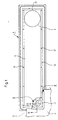
- the drainage gully 1 illustrated in the drawings is adapted to be mounted in a floor 2 so that a floor mat 3, preferably of a plastic material, provided on the floor 2 can be connected therewith.
- a floor mat 3 preferably of a plastic material
- the purpose herewith is that water on the floor mat 3 shall flow down into the drainage gully 1 and through said drainage gully into a drainage system (not shown).
- the drainage gully 1 is four-sided and preferably has a rectangular shape.
- the bottom 4 thereof has an opening 5 and it slopes towards this opening 5 so that collected water flows down into the opening 5 and through said opening into the drainage system.
- the drainage gully 1 also includes four sidewalls 6 which are vertically or substantially vertically directed when the drainage gully 1 has been placed in operating position in the floor 2. At the top, each sidewalls 6 is provided with an outwardly directed flange 7 which forms right or substantially right angles to each sidewall 6 and which might include a somewhat upwardly inclined portion.
- the outwardly directed flange 7 extends around the entire drainage gully 1 and it is preferably somewhat depressed below the floor level so that the floor mat 3 can engage the upper or top surface thereof without defining a threshold preventing water from flowing down into the drainage gully 1.
- a carrier member 8 can be located in the drainage gully 1 and a grating means 9 can be provided in said carrier member.
- the grating means 9 has the shape of a foursided frame 10 with a grate which allows water to flow down into the drainage gully 1, but prevents people from treading or driving down thereinto.
- the height of the grating means 9 is adapted so that the upper or top side thereof is in level with or somewhat below the upper or top surface of the carrier member 8.
- the carrier member 8 includes a central portion 11 which at the top transfers into an outwardly directed clamping flange 12 and down below transfers into an inwardly directed support flange 13.
- the length of the central portion 11 is substantially less than the distance between the outwardly directed flange 7 and a mounting flange 14 provided in the drainage gully 1, so that the support flange 13 can not come on contact with said mounting flange.
- the clamping flange 12 is adapted to engage the floor mat 3 from above and press said floor mat downwards against the outwardly directed flange 7, such that excellent sealing is obtained between the floor mat 3 and the flange 7, whereby water is prevented from penetrating into the floor 2 beside the drainage gully 1. This sealing becomes particularly advantageous since neither the floor mat 3, the outwardly directed flange 7 nor the clamping flange 12 is provided with holes for mounting means or similar.
- the carrier member 8 preferably has such an original shape that the angle ⁇ between the central portion 11 and the clamping flange 12 is less than 90°, e.g. about 85°, whereby the outer portions 15 of the clamping flange 12 can be brought to engage the floor mat 3 with a larger pressure than inner portions thereof.
- the original position of the clamping flange 12 is shown with solid lines in fig. 2.
- the carrier member 8 preferably consists of or includes such resilient material that the clamping flange 12 can be brought to change position relative to the central portion 11 so that said angle ⁇ increases to a larger angle ⁇ , preferably maximum 90°, when the clamping flange 12 during mounting of the carrier member 8 engages the floor mat 3 and said carrier member is subjected to forces in a downward direction relative to the drainage gully 1, whereby major portions of the width of the clamping flange 12 will engage the floor mat 3. However, outer portions 15 of the clamping flange 12 will still engage the floor mat 3 with a larger pressure than inner portions thereof. Said latter position of the clamping flange 12 is shown with dashed and dotted lines in fig. 2 and with solid lines in fig. 3.
- the carrier member 8 can be drawn down into the drainage gully 1 by means of mounting means 16 of a suitable type. These mounting means are threaded through holes 17 in the support flange 13 and they are screwed down into or cooperate in another way with the mounting flange 14 so that the carrier member 8 can be drawn or pulled downwards relative to the mounting flange 14 by screwing down the mounting means 16 in relation thereto.
- the carrier member 8 can be screwed downwards so far that the clamping flange 12 press the floor mat 3 downwards against the outwardly directed flange 7 with a large pressure which can be maintained for a long time even if the floor mat 3 is compressed.
- This function is improved while the carrier member 8 has resilient properties and/or thanks to the shape of the carrier member and particularly the original shape of the clamping flange 12.
- the spring means described below also contribute to a certain degree to this improved function.
- each mounting means 16 consists of a screw 18 with a threaded portion 19 through which it is screwed into a threaded hole 20 in the mounting flange 14.
- the screw 18 can be screwed down into the hole 20 until the clamping flange 12 attains said clamping effect against the floor mat 3.
- each mounting means 16 consists of another type of screw 21, namely a screw with a part 22 which with clearance protrudes down through a hole 23 in the mounting flange 14.
- This part 22 has a threaded portion 24 onto which a nut 25 is provided and between the mounting flange 14 and said nut 25 there is located at least one spring means 26 so that said spring means through the screw 21 exerts downwardly directed forces on the carrier member 8 and its clamping flange 12.
- the spring means 26 can be a helical spring threaded onto the screw, one or more cup springs or another suitable type of permanently functioning springs with required endurance.
- the support flange 13 preferably has recessed portions 27 around each hole 17 for the mounting means 16. These recessed portions 27 are formed so that they accommodate the parts 28, preferably so called screw heads, of the mounting means 16 located above the support flange 13, so that said parts 28 do not protrude up and above those engaging surfaces 29 on the support flange 13 which the frame 10 of the grating means 9 is adapted to engage. These recessed portions 27 can be defined by bending down the support flange 13 around the holes 17 or in any other suitable way. The recessed portions 27 see to that the grating means 9 does not directly load the mounting means 16 and that said parts 28 of said mounting means can not wear out the frame 10 of the grating means 9.
- the mounting flange 14 preferably consists of a section which is fixedly mounted on the sidewalls 6 a distance above the bottom 4 and which preferably extends in a closed shape e.g. as a closed frame, internally along the walls of the drainage gully 1, which means that the section provides an advantageous reinforcement of the drainage gully 1.
- the section may have one or more holes 17 for the mounting means 16 at each side of the drainage gully 1 and it is preferably attached to all four sides 6 of said drainage gully.
- the mounting flange 14 preferably further includes an L-section, one shank 30 of which is directed downwards and attached to the sidewall 6 of the drainage gully 1, while the other shank 31 protrudes out from said sidewall 6, whereby it preferably forms right angles with the shank 30.
- the mounting means 16 preferably are provided in the support flange 13 so that they are covered by the frame 10 of the grating means 9, the support flange 13 preferably is as wide or wider than the mounting flange 14 so that said support flange 13, seen from above, covers said mounting flange 14 and the outer portions 15 of the clamping flange 12 preferably has a chamber 32 down below at the outer edge for permitting advantageous connection with the floor mat 3.
- the drainage gully 1 can be of another type of discharge device for draining off water from floors; the drainage gully can have a totally different shape than that shown and also the carrier member to a certain extent and/or the mounting flange and/or the grating means can have another shape or other shapes than those shown.
Landscapes
- Engineering & Computer Science (AREA)
- Health & Medical Sciences (AREA)
- Life Sciences & Earth Sciences (AREA)
- Hydrology & Water Resources (AREA)
- Public Health (AREA)
- Water Supply & Treatment (AREA)
- Structural Engineering (AREA)
- Architecture (AREA)
- Civil Engineering (AREA)
- Carpets (AREA)
- Passenger Equipment (AREA)
- Liquid Developers In Electrophotography (AREA)
- External Artificial Organs (AREA)
- Centrifugal Separators (AREA)
- Sink And Installation For Waste Water (AREA)
- Electrical Discharge Machining, Electrochemical Machining, And Combined Machining (AREA)
- Sewage (AREA)
- Load-Engaging Elements For Cranes (AREA)
- Motor Or Generator Cooling System (AREA)
- Vehicle Body Suspensions (AREA)
- Mechanical Treatment Of Semiconductor (AREA)
- Formation And Processing Of Food Products (AREA)
- Polarising Elements (AREA)
- Paper (AREA)
- Amplifiers (AREA)
- Bipolar Transistors (AREA)
- Optical Communication System (AREA)
Abstract
Description
Claims (6)
- Clamping device at a drainage gully or similar, whereby the drainage gully (1) at the top is provided with an outwardly chute directed flange (7) which is engaged by a floor mat (3), preferably of a plastic material, and whereby the drainage gully includes a carrier member (8) for grating means (9) which carrier member engages the floor mat and cooperates through mounting means (16) with a mounting flange (14) provided in the drainage gully in such a way that the carrier member press the floor mat against the outwardly directed flange of the drainage gully, characterized in that the carrier member (8) includes a central portion (11) which at the top transfers into an outwardly directed clamping flange (12) for clamping the floor mat (3) against the outwardly directed flange (7) of the drainage gully (1), and which down below transfers into an inwardly directed support flange (13) which is engaged by the grating means (9) and which through the mounting means (16) cooperates with the mounting flange (14) of the drainage gully, that the carrier member (8) consists of or includes resilient material so that the clamping flange (12) thereof can adapt to the floor mat (3) even if said floor mat is compressed, and that the length of the carrier member (8) is less than the distance between the outwardly directed flange (7) of the drainage gully (1) and the mounting flange (14) provided in the drainage gully (1) so that the support flange (13) is not brought in contact with the mounting flange when said support flange is in its lowermost position.
- Clamping device according to claim 1, characterized in that the carrier member (8) has such a shape that the angle (α) between the central portion (11) thereof and the clamping flange (12) is less than 90°, preferably about 85°, whereby outer portions (15) of the clamping flange (12) can be brought to engage the floor mat (3) with a larger pressure than inner portions thereof and that the carrier member (8) consists of or includes such resilient material that the clamping flange (12) can be made to spring upwards relative to the central portion (11) so that said angle (α) increases to a larger angle (α), preferably maximum 90°, when the clamping flange (12) during mounting of the carrier member (8) engages the floor mat (3) and said carrier member is subjected to forces in a downward direction relative to the drainage gully (1).
- Clamping device according to claim 2, characterized in that the carrier member (8) through the mounting means (16) can be brought to engage the mounting flange (14) in such a way that outer portions (15) of the clamping flange (12) engage the floor mat (3) with greater clamping forces than inner portions of said clamping flange.
- Clamping device according to any preceding claim, characterized in that the mounting flange (14) consists of a section which is fixedly mounted on sidewalls (6) of the discharge chute (1) a distance above the bottom (4) of said drainage gully and which internally extends around the drainage gully (1) in a closed shape, whereby the section reinforces the drainage gully (1).
- Clamping device according to claim 4, whereby the discharge chute (1) is foursided and has a rectangular shape, characterized in that the support flange (13) is provided to extend as a closed frame located an internally in the drainage gully (1), which is attached to all four sides of said drainage gully and that the mounting flange (14) has holes (17) for mounting means (16) along all four sides of said drainage gully.
- Clamping device according to any preceding claim, characterized in that the mounting flange (14) consists of an L-section, one shank (30) of which is directed downwards and attached to the sidewall (6) of the drainage gully (1) while the other shank (31) protrudes out from said sidewall (6) and has holes (17) for the mounting means (16).
Applications Claiming Priority (2)
| Application Number | Priority Date | Filing Date | Title |
|---|---|---|---|
| SE9400345A SE506414C2 (en) | 1994-02-03 | 1994-02-03 | Device for drainage channels with support part for screening means |
| SE9400345 | 1994-02-03 |
Publications (2)
| Publication Number | Publication Date |
|---|---|
| EP0666378A1 EP0666378A1 (en) | 1995-08-09 |
| EP0666378B1 true EP0666378B1 (en) | 1998-09-23 |
Family
ID=20392789
Family Applications (1)
| Application Number | Title | Priority Date | Filing Date |
|---|---|---|---|
| EP95100669A Expired - Lifetime EP0666378B1 (en) | 1994-02-03 | 1995-01-19 | Drainage gully |
Country Status (7)
| Country | Link |
|---|---|
| EP (1) | EP0666378B1 (en) |
| AT (1) | ATE171497T1 (en) |
| DE (1) | DE69504874T2 (en) |
| DK (1) | DK0666378T3 (en) |
| FI (1) | FI104104B1 (en) |
| NO (1) | NO318261B1 (en) |
| SE (1) | SE506414C2 (en) |
Families Citing this family (5)
| Publication number | Priority date | Publication date | Assignee | Title |
|---|---|---|---|---|
| DE29610312U1 (en) * | 1996-06-12 | 1996-08-22 | Fa. Franz Viegener Ii, 57439 Attendorn | Drain fitting, preferably for a shower tray |
| US8474068B2 (en) * | 2010-01-05 | 2013-07-02 | Noble Company | Trench shower drain |
| DE102010024018A1 (en) * | 2010-06-16 | 2011-12-22 | Buchberger Gmbh Profilsysteme | Discharge groove for mounting arrangement in concrete floor in e.g. multi-storey car parking place in building to discharge fluid, has flange that is set back around height displacement toward body base to form reinforcement unit |
| NL2006553C2 (en) * | 2011-04-06 | 2012-10-09 | Easy Sanitairy Solutions Bv | CLAMP CONSTRUCTION FOR DRAINAGE. |
| CN112127459B (en) * | 2020-09-25 | 2021-10-15 | 北京市第三建筑工程有限公司 | Support structure, large-load trench cover plate structure and construction method |
Family Cites Families (6)
| Publication number | Priority date | Publication date | Assignee | Title |
|---|---|---|---|---|
| GB731408A (en) * | 1953-07-01 | 1955-06-08 | J A Zurn Mfg Co | Steam heated roof and area drain |
| GB869675A (en) * | 1959-02-10 | 1961-06-07 | Burn Brothers London Ltd | Improvements relating to drainage devices |
| GB1247536A (en) * | 1968-12-11 | 1971-09-22 | Josam Mfg Co | Improvements in and relating to drains |
| DE3925317A1 (en) * | 1989-07-31 | 1991-02-07 | Dallmer Gmbh & Co | FLOOR DRAIN |
| DE8913129U1 (en) * | 1989-11-07 | 1990-06-07 | Hauraton Betonwarenfabrik GmbH & Co KG, 7550 Rastatt | Gutter component, in particular for a drainage channel |
| DE9317601U1 (en) * | 1993-11-18 | 1994-01-27 | Zink, Walter, 72669 Unterensingen | Inlet funnel with variable flange ring |
-
1994
- 1994-02-03 SE SE9400345A patent/SE506414C2/en not_active IP Right Cessation
-
1995
- 1995-01-19 DK DK95100669T patent/DK0666378T3/en active
- 1995-01-19 DE DE69504874T patent/DE69504874T2/en not_active Expired - Fee Related
- 1995-01-19 AT AT95100669T patent/ATE171497T1/en not_active IP Right Cessation
- 1995-01-19 EP EP95100669A patent/EP0666378B1/en not_active Expired - Lifetime
- 1995-01-25 NO NO19950266A patent/NO318261B1/en unknown
- 1995-02-01 FI FI950445A patent/FI104104B1/en not_active IP Right Cessation
Also Published As
| Publication number | Publication date |
|---|---|
| DK0666378T3 (en) | 1999-06-14 |
| FI950445A0 (en) | 1995-02-01 |
| SE506414C2 (en) | 1997-12-15 |
| NO950266D0 (en) | 1995-01-25 |
| EP0666378A1 (en) | 1995-08-09 |
| FI950445A7 (en) | 1995-08-04 |
| FI104104B (en) | 1999-11-15 |
| SE9400345D0 (en) | 1994-02-03 |
| NO318261B1 (en) | 2005-02-28 |
| SE9400345L (en) | 1995-08-04 |
| DE69504874D1 (en) | 1998-10-29 |
| DE69504874T2 (en) | 1999-05-27 |
| NO950266L (en) | 1995-08-04 |
| ATE171497T1 (en) | 1998-10-15 |
| FI104104B1 (en) | 1999-11-15 |
Similar Documents
| Publication | Publication Date | Title |
|---|---|---|
| US5966959A (en) | Condensate drain pan arrangement with positive slope | |
| US4919564A (en) | Manhole insert | |
| US8578523B2 (en) | Vandal-proof floor sink strainer | |
| US5401114A (en) | Manhole ventilation insert with duct shut-off device | |
| CA2263303A1 (en) | Drinking receptacle covers | |
| US5249398A (en) | Cesspool | |
| EP0666378A1 (en) | Device at discharge chute | |
| GB2267749A (en) | Collecting apparatus for fluid drainage | |
| US5302283A (en) | Leaf guard and strainer assembly for a gutter downspout | |
| RU2327841C2 (en) | Fastening device | |
| JPH04117914U (en) | Cap for rail mounting hole of linear guide device | |
| KR19980042853A (en) | Floor plate for fixing the hinge of the furniture | |
| US5575903A (en) | Drain water-intake cover | |
| US5336954A (en) | Drain unit of starter | |
| US5802777A (en) | Protection cover for eaves gutter | |
| GB2094847A (en) | A drainage trap | |
| WO1991016505A1 (en) | Manhole inserts | |
| GB2233016A (en) | Drainage gully | |
| KR102308019B1 (en) | Odor blocking device for rainwater manhole | |
| KR102332070B1 (en) | Grating device | |
| KR200252798Y1 (en) | Bad smell cutoff equipment of drain manhole | |
| EP0953687A3 (en) | Height compensation device between a manhole cover and a road surface | |
| FI81421B (en) | GOLVBRUNN. | |
| KR200205751Y1 (en) | Height adjustment of the manhole cover | |
| JPS644945Y2 (en) |
Legal Events
| Date | Code | Title | Description |
|---|---|---|---|
| PUAI | Public reference made under article 153(3) epc to a published international application that has entered the european phase |
Free format text: ORIGINAL CODE: 0009012 |
|
| AK | Designated contracting states |
Kind code of ref document: A1 Designated state(s): AT BE CH DE DK ES FR GB LI NL SE |
|
| 17P | Request for examination filed |
Effective date: 19960116 |
|
| GRAG | Despatch of communication of intention to grant |
Free format text: ORIGINAL CODE: EPIDOS AGRA |
|
| 17Q | First examination report despatched |
Effective date: 19970911 |
|
| GRAG | Despatch of communication of intention to grant |
Free format text: ORIGINAL CODE: EPIDOS AGRA |
|
| GRAH | Despatch of communication of intention to grant a patent |
Free format text: ORIGINAL CODE: EPIDOS IGRA |
|
| GRAH | Despatch of communication of intention to grant a patent |
Free format text: ORIGINAL CODE: EPIDOS IGRA |
|
| GRAA | (expected) grant |
Free format text: ORIGINAL CODE: 0009210 |
|
| AK | Designated contracting states |
Kind code of ref document: B1 Designated state(s): AT BE CH DE DK ES FR GB LI NL SE |
|
| PG25 | Lapsed in a contracting state [announced via postgrant information from national office to epo] |
Ref country code: LI Free format text: LAPSE BECAUSE OF FAILURE TO SUBMIT A TRANSLATION OF THE DESCRIPTION OR TO PAY THE FEE WITHIN THE PRESCRIBED TIME-LIMIT Effective date: 19980923 Ref country code: FR Free format text: LAPSE BECAUSE OF FAILURE TO SUBMIT A TRANSLATION OF THE DESCRIPTION OR TO PAY THE FEE WITHIN THE PRESCRIBED TIME-LIMIT Effective date: 19980923 Ref country code: ES Free format text: THE PATENT HAS BEEN ANNULLED BY A DECISION OF A NATIONAL AUTHORITY Effective date: 19980923 Ref country code: CH Free format text: LAPSE BECAUSE OF FAILURE TO SUBMIT A TRANSLATION OF THE DESCRIPTION OR TO PAY THE FEE WITHIN THE PRESCRIBED TIME-LIMIT Effective date: 19980923 Ref country code: BE Free format text: LAPSE BECAUSE OF FAILURE TO SUBMIT A TRANSLATION OF THE DESCRIPTION OR TO PAY THE FEE WITHIN THE PRESCRIBED TIME-LIMIT Effective date: 19980923 Ref country code: AT Free format text: LAPSE BECAUSE OF FAILURE TO SUBMIT A TRANSLATION OF THE DESCRIPTION OR TO PAY THE FEE WITHIN THE PRESCRIBED TIME-LIMIT Effective date: 19980923 |
|
| REF | Corresponds to: |
Ref document number: 171497 Country of ref document: AT Date of ref document: 19981015 Kind code of ref document: T |
|
| RIN1 | Information on inventor provided before grant (corrected) |
Inventor name: ESKIL, ANDERSSON LEIF |
|
| REG | Reference to a national code |
Ref country code: CH Ref legal event code: EP |
|
| REF | Corresponds to: |
Ref document number: 69504874 Country of ref document: DE Date of ref document: 19981029 |
|
| PG25 | Lapsed in a contracting state [announced via postgrant information from national office to epo] |
Ref country code: GB Free format text: LAPSE BECAUSE OF NON-PAYMENT OF DUE FEES Effective date: 19990119 |
|
| EN | Fr: translation not filed | ||
| REG | Reference to a national code |
Ref country code: CH Ref legal event code: PL |
|
| REG | Reference to a national code |
Ref country code: DK Ref legal event code: T3 |
|
| PLBE | No opposition filed within time limit |
Free format text: ORIGINAL CODE: 0009261 |
|
| STAA | Information on the status of an ep patent application or granted ep patent |
Free format text: STATUS: NO OPPOSITION FILED WITHIN TIME LIMIT |
|
| GBPC | Gb: european patent ceased through non-payment of renewal fee |
Effective date: 19990119 |
|
| 26N | No opposition filed | ||
| PGFP | Annual fee paid to national office [announced via postgrant information from national office to epo] |
Ref country code: SE Payment date: 20050126 Year of fee payment: 11 Ref country code: DK Payment date: 20050126 Year of fee payment: 11 |
|
| PGFP | Annual fee paid to national office [announced via postgrant information from national office to epo] |
Ref country code: NL Payment date: 20050131 Year of fee payment: 11 |
|
| PGFP | Annual fee paid to national office [announced via postgrant information from national office to epo] |
Ref country code: DE Payment date: 20050224 Year of fee payment: 11 |
|
| PG25 | Lapsed in a contracting state [announced via postgrant information from national office to epo] |
Ref country code: SE Free format text: LAPSE BECAUSE OF NON-PAYMENT OF DUE FEES Effective date: 20060120 |
|
| PG25 | Lapsed in a contracting state [announced via postgrant information from national office to epo] |
Ref country code: DK Free format text: LAPSE BECAUSE OF NON-PAYMENT OF DUE FEES Effective date: 20060131 |
|
| PG25 | Lapsed in a contracting state [announced via postgrant information from national office to epo] |
Ref country code: NL Free format text: LAPSE BECAUSE OF NON-PAYMENT OF DUE FEES Effective date: 20060801 Ref country code: DE Free format text: LAPSE BECAUSE OF NON-PAYMENT OF DUE FEES Effective date: 20060801 |
|
| REG | Reference to a national code |
Ref country code: DK Ref legal event code: EBP |
|
| EUG | Se: european patent has lapsed | ||
| NLV4 | Nl: lapsed or anulled due to non-payment of the annual fee |
Effective date: 20060801 |