EP0664656A2 - Digital electronic intermediate distribution frame for message- and data-communication systems - Google Patents
Digital electronic intermediate distribution frame for message- and data-communication systems Download PDFInfo
- Publication number
- EP0664656A2 EP0664656A2 EP94117980A EP94117980A EP0664656A2 EP 0664656 A2 EP0664656 A2 EP 0664656A2 EP 94117980 A EP94117980 A EP 94117980A EP 94117980 A EP94117980 A EP 94117980A EP 0664656 A2 EP0664656 A2 EP 0664656A2
- Authority
- EP
- European Patent Office
- Prior art keywords
- status signal
- data
- line
- bit packets
- memory
- Prior art date
- Legal status (The legal status is an assumption and is not a legal conclusion. Google has not performed a legal analysis and makes no representation as to the accuracy of the status listed.)
- Withdrawn
Links
Images


Classifications
-
- H—ELECTRICITY
- H04—ELECTRIC COMMUNICATION TECHNIQUE
- H04Q—SELECTING
- H04Q11/00—Selecting arrangements for multiplex systems
- H04Q11/04—Selecting arrangements for multiplex systems for time-division multiplexing
Definitions
- the invention relates to a digital electronic intermediate distributor for message and data transmission systems and to a method for message and data transmission.
- Telephone systems transmit information from an exchange to the telephone subscribers.
- the Information contains the status of the subscriber loop, "free / busy", and voice or data signals that come from various subscribers or are transmitted to them.
- the communication lines generally run from the exchange to a distributor interface, which is also called an intermediate distributor.
- this intermediate distributor establishes an electrically conductive connection from the exchange to the subscriber.
- changes in the connection to the intermediate distributor lead to physical changes in the wiring in the device.
- it is relatively complex to make a change in the electrical connection between a subscriber and the switching center.
- U.S. Patent 4,520,234 discloses a cable switching system that uses a logic array and a switching matrix with a record of the current matrix state of the switching subsystem.
- the switching matrix module is formed by a large number of relays.
- U.S. Patent 4,539,564 discloses a central matrix made up of a plurality of semiconductor analog switches.
- U.S. Patent 4,525,605 also discloses a system that uses relays to access the telephone lines.
- US Patent 3,562,435 discloses a switching system with an automatic main distributor.
- the system contains a network control circuit for controlling a switching network with a relay which is installed between the telephone lines.
- an intermediate distributor for connecting voice circuits between input and output connections, such as a connection with a subscriber and a connection with a switching center.
- Each subscriber connection is connected to a line card or a subscriber interface module (SIM) arranged on a line of an intermediate distributor.
- SIM subscriber interface module
- NIM network interface module
- the line cards (hybrids) convert the analog signals into digital signals that are processed by the intermediate distributor.
- digital interface connections can be provided (preferably with four digital line cards) which establish a connection with a data communication line which transmits compressed digital data.
- the line cards are connected to an interface unit for a voice frequency time channel for coupling network voice frequency signals with subscriber voice frequency signals (and vice versa).
- the signaling time channel interface unit is also provided for connecting loop signaling data from network line cards to the subscriber line cards (and vice versa).
- the signaling time channel interface contains one or more memories with two connections (random access memory, RAM), which are controlled by a sequential counter. After all time channels have been loaded, the incoming signaling data is replaced by a value from a look-up table, which is then written as a new signal (encoded on the outgoing line) into an address table (data grooming). The microprocessor can also write the data directly to the outgoing address (no data grooming). The data leaves the look-up table and is saved in an address table before it reaches the outgoing line card.
- RAM random access memory
- a hardware interrupt circuit is added to the lookup tables to notify the microprocessor that an illegal data packet has been received from the lookup tables. Since the incoming data is signaling data (which represents the status of a line, such as the subscriber line), the hardware interrupt circuit provides a mechanism for detecting errors. The software can use this error detection scheme by loading the top two bits of a valid data address with ones and loading an invalid data address with a zero in each position. If the "zero" is loaded with the highest position, an interrupt is triggered at the high level. If the "zero" is loaded into the next higher position, an interrupt is triggered at the low level. The interrupt circuit can be disabled for any interconnect where the high level interrupt can be masked after an interrupt occurs to allow detection of a return to a normal interrupt state (for example, if a line card is removed and replaced) becomes).
- FIG. 1 shows an intermediate distributor 1 for switching and monitoring the data exchange via individual network lines 15 and subscriber lines 12.
- Subscriber lines 12 are provided, each of which is connected to a subscriber 10 and a line card 20.
- the lines 12 are supplied and the loop current is monitored via the line card 20 (FIG. 2, 3).
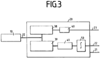
- 3 shows that the signal from subscriber 10 or switching center 2, if line card 20 is connected to network lines 15, is separated in line card 20.
- the data component usually the voice component, is passed from the data separator 38 to an analog / digital converter 40, the status signals separated in the status signal separator 39 are sent to an encoder / decoder 41.
- the encoder 41 converts the status signals into 8-bit packets or bytes at 8 kHz.
- Each status signal preferably has its own bit address; the data in this bit address indicate whether the status signal is present or not.
- the 8-bit packets or bytes can be passed to an integrator 50 for handling.
- the integrator 50 integrates or averages the status signals to remove noise spikes that would otherwise appear as erroneous message traffic.
- the integration or averaging can take place via a constantly moving window, or the status signals can be integrated or averaged at a lower rate.
- the integration eliminates misinterpretations of the line signals during later processing. Accordingly, through this processing the signals from the line card 20 are converted into event messages which are routed via channels 21, 22, 23 to a call processor, among other things, which has a well-functioning organization for each of the various lines.
- the 8-bit packets or bytes are routed from the line card 20 to a signaling TSI 102 (time channel interface).
- the signaling TSI 102 redirects the incoming status signals to the correct outgoing line with the correct time channel. This diversion takes place via assigned lines under the control of the switching center 2.
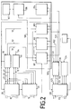
- Fig. 2 shows the system architecture with line cards 20 with thirty-two analog interface connections for processing the signals from the subscriber lines 12 and line cards 20 with thirty-two analog interface connections for processing the signals from the network lines 15 and the main control unit 104 and the connecting communication channels.
- the system is based on central processing, which is supported by control modules which are arranged at the common control point of the control unit 100. All secondary processors that are not arranged on the common control unit 100 are subordinate and are controlled by a plurality of internal communication buses, which are also shown in FIG. 2.
- the speech processing takes place in the time channel interface unit 103 for the voice frequency (VF).
- the processing is not intrusion and provides an interconnection of the language circles between the connections.
- a test pattern can be introduced and brought out from a speech PCM signal (pulse code modulation) for the purpose of a feedback test.
- the line circuit signaling is queried and brought to the signaling TSI 102 via a local processor 200 (FIGS. 5, 6).
- the status of the line circuit is monitored via NIM and SIM status registers (NIM means network interface modules, SIM means subscriber interface modules).
- NIM means network interface modules
- SIM means subscriber interface modules
- a bit pack scheme is provided which allows a local processor 200 to observe and send a call to the status registers in the signaling TSI 102.
- the SIM status register shows the status of the handset switch and the presence of the ring ground.
- the NIM status register shows loop detection forwards and backwards, presence of plug or ring earthing and the function "ringing".
- the communication bus 105 connects the main control unit 104, the digital group controller 130, the time channel interface unit 103, the signaling TSI unit 102 and the operator interface 106 to the Front panel 107.
- the system is preferably provided with full redundancy using a redundant module with a Bus structure executed, which is identical to that described above (two separate systems A and B).
- the group control module 30 for system A is identical to the group control module 33 for system B.
- system B which is identical to system A, is only shown up to connection 34.
- the communication bus 105 is very time-critical and is the main communication in the common control unit 100.
- This bus 105 is designed as an Ethernet network in a hub configuration.
- This bus 105 is duplicated for the A and B systems of the common control unit 100.
- Ethernet can be used as a "logical pipe", as a datagram or broadcast mode bus.
- the "digital bank" controls 130 in the DS1 bank are preferably accessible via the communication bus 105.
- test and configuration modules 101 transmit and receive non-real-time information from the line cards 20.
- the C and T connection interface (configuration and testing) is a 2 Mb / s control interface which is provided for each line card 20.
- the C and T interfaces are routed to the group control module 30 and again distributed over seven individual 2 Mb / s interfaces. These seven channels are distributed over the line cards 20.
- the C and T channels 21, 31 are used to write configuration information (control register A) to the individual line cards 20 (hybrids).
- the C and T channels 21, 31 are located where the transmission and reception filter is controlled for amplification and attenuation with respect to the encoder 41. This is also where the CODEC operating modes "normal”, "digital loopback", “analog loopback” and "no supply" are specified.
- the signal channel 32 is routed to the line card 20.
- the channel 32 is demultiplexed at the group controller 30 and again distributed as seven individual 2 Mb channels 22, one for each line card 20.
- the signal channel reading function supplies the main control unit 104 with signature information via the line cards 20, Display of a blown fuse and display group control 30 A or B active.
- the system according to the invention preferably supports 18 line compartments, 4032 connections.
- the maximum requirement is for a fully configured interconnection, where 2016 network interface modules and 2016 subscriber interface modules are supported.
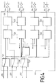
- FIG. 4 shows a quadruple DS1 module 120
- DS1 module 120 is a digital line card with 32 digital connections that are connected to digital lines 112.
- the digital lines 112 carry digitally compressed data signals at a DS1 rate (1.55 Mb / s).
- the digital module 120 has four connections 124 for each of the DS1 lines 1 to 4.
- Each connection 124 is connected to a combiner 126 via a data transmission buffer 125.
- the combiner 126 combines the outgoing speech frequency and signaling data from the intermediate distributor 1 and separates the incoming speech frequency and signaling data for input into the intermediate distributor 1.
- the communication signals can also be separated or combined in the combiner 126.
- the speech frequency signals are routed from the speech frequency selection unit 127 via the PCM-VF bus 123.
- the communication signals are routed through the communication selector 127 (to select system A or B, whichever of them is active) and via the communication bus 105.
- the signaling data are sent out via the signal bus 122.
- a configuration and test bus 131 (FIG. 2) is provided in the described type of configuration and test bus 121.
- the signal selection unit 129 and the speech frequency selection unit 128 select either system A or system B, whichever is active.
- FIG. 5 shows the digital group controller 130, which routes the signals to the line cards 20 and receives signals from the digital line cards 20, and the Forwards signals to or from the TSI unit 103 or the signal TSI unit 102.
- the signals from (to) the line cards 20 can be multiplexed (demultiplexed) in the unit 134 for forwarding via the signal bus 132 to the signal TSI unit 102.
- the voice frequency signals are transmitted via the bus 133 with the VF-TSI Unit 103 and connected to a configuration and test bus 131, which connects the digital group controller 130 to the test and configuration module 101.
- the outputs 135 of the unit 134 lead to the connections 124 of the quadruple DS1 module 120 (FIG. 4).
- FIG. 6 shows the structure of the signal TSI unit 102.
- the TSI unit 102 is a signaling time channel interface with full access, in which signals are routed from the network lines 15 and also from the subscriber lines 12 into the TSI unit 102 .
- the signal data for the network lines 15 as well as for the subscriber lines 12 are output by the TSI unit 102. This enables flexibility, including the possibility of connecting network line 15 to network line 15.
- the TSI unit 102 contains a microprocessor 200.
- the microprocessor 200 is connected to the exchange 2 via an assigned line (such as an assigned time channel).
- the exchange 2 then controls the microprocessor 200 via a software network manager to determine the time channels for the signaling data and other data (voice frequency data).
- the 8-bit packets or bytes received by the line cards 20 can be treated in a bit-pack process, with status changes in the various lines being detected and communicated to the switching center 2 and the subscriber 10.
- the signaling data from the line cards 20 reach the TSI unit 102 via the 8 Mb / s bus 32, as described above and shown in FIG.
- the data is demultiplexed to a data rate of 2 Mb / s and then transferred to a serial / parallel converter.
- the data leave the serial / parallel converter as 8 bit wide packets with a 16 MHz rate.
- the data is then loaded sequentially into both memories 202, 204 via a sequential counter 205.
- the lower path shown in Fig. 6 is used by the event detection software.
- the two ports of memory 204 are bank switched and the data is loaded in bit packets into another two ports of memory 204 for reading by microprocessor 200.
- the microprocessor 200 for data evaluation and data determination has an address output 201 and a data input 203 to the memory 204 and an address output 207 and a data output 209 to the connection memory 206.
- the bit packets are placed in memory locations where a bit pack device reads the least significant bit and then the next least significant bit, etc. Bit packing is performed on all bits and is banked when all 2048 time channels are loaded are.
- the microprocessor 200 can then be used for event detection with software that can output new signaling data for the outgoing line card via the connection memory 206 and the lookup tables 208.
- the microprocessor 200 can be used in a more limited manner, or a comparison can be carried out on the basis of the output of the software system explained above, the data being output via a further time channel exchange, as in FIG following is described.
- the data coming in via channel 32 (network signaling data and subscriber signaling data) can be routed to memory 202 via the upper path shown in FIG. 6.
- Memory 202 preferably has two banks that allow writing and reading without problems.
- the microprocessor 200 (under the control of the exchange 2) provides time channels, the address of the data being stored in the memory 202 in the connection memory 206 in accordance with the established time channels.
- a sequential counter 210 sequentially increments the link memory 206, whereby link data is read from the memory 202 in time according to the link plan address. This data then becomes part of an address along with higher bits from link memory 206.
- connection data and the higher bits can then become a code of the outgoing network or subscriber line card (Data grooming) can be changed if necessary.
- Data grooming can be changed if necessary.
- the new data correspond to signal data for an outgoing line card 20, and the data read out from the connection memory 206 correspond to the data for an incoming line card 20.
- memory 204 receives data based on the address of line card 20.
- Memory 204 preferably has two banks, one bank being written and the other bank used to avoid conflicts.
- the data is written to one side (left) of memory 204 and read at the same location in memory 204 in a different bank (such as data at ADD 0002) in microprocessor 200.
- the microprocessor 200 can be used to evaluate and update the data or to force signal data when a problem is detected.
- the microprocessor 200 writes new data into an address position of the connection memory 206.
- the address position is determined by the exchange 2 and provides the time channel for the outgoing data. For example, data from ADD 0002 are evaluated and new data are written into ADD 0128 of the connection memory 206, which is currently an address. represents a corresponding data code to be sent.
- the sequential counter 210 sequentially reads data from the connection memory 206, which form an address for the following time channels. Then lookup table 208 is used, reading the data from incoming memory 202 based on its placement in link memory 206 (one address in time). The data then becomes part of the address along with the higher bits from link memory 206 for lookup table 208 with the output data or new data 212 in that selected address position. The new data 212 is then output to a parallel / serial converter, the data leaving the lookup tables 208 as an 8 bit packet and converted to serial data and then preferably multiplexed to a higher rate (e.g. 8 Mb / s) with which they are routed via bus 32 or bus 132 to a line card 20 or 120.
- a higher rate e.g. 8 Mb / s
- Processing the data for the time channel exchange as explained above provides several advantages.
- An important advantage of the exchange from lookup tables is that the microprocessor is freed up for other tasks.
- a hardware interrupt circuit can be added to the Lookup tables are used to inform the microprocessor when an illegal data packet has been received from the lookup tables. Since the look-up tables have the necessary bit packets with regard to the various signaling data, an error can be detected immediately. Since the top two bits of the lookup data are not sent to the outgoing address, this can be used to indicate a valid data address. The software can then take advantage of this possibility by loading the upper two bits of a valid data address with "one" and invalid data addresses with "zero" at each position.
- an interrupt can be triggered at the high level. If the "zero" is loaded into the next highest position, an interrupt can be triggered at the low level. Flexibility can be added to enable and disable the interrupt circuit for each interconnect. The high level interrupt can be masked after an interrupt has occurred to allow detection of a return to the normal interrupt (for example, if a line card has been removed and replaced). While particular embodiments have been shown and described in more detail to illustrate the application of the principles according to the present invention, it is obvious that the invention can be carried out in other ways without deviating from such principles.
Landscapes
- Engineering & Computer Science (AREA)
- Computer Networks & Wireless Communication (AREA)
- Use Of Switch Circuits For Exchanges And Methods Of Control Of Multiplex Exchanges (AREA)
- Sub-Exchange Stations And Push- Button Telephones (AREA)
Abstract
Die Erfindung bezieht sich auf einen digitalen elektronischen Zwischenverteiler für Telefon- und Datenübertragungssysteme. Es soll ein Zwischenverbinder entwickelt werden, der flexibel ist und eine paarweise Zwischenverbindung sowie eine zusätzliche Basis für weitere Anwendungen gewährleistet. Hierzu weist der digitale Zwischenverbinder eine Vielzahl von Line-Cards 20, einschließlich von mit einer Netzleitung 15 verbundenen Line-Cards 20 und mit einer Teilnehmerleitung 12 verbundenen Line-Cards 20 auf. Die Netzleitung 15 und die Teilnehmerleitung 12 übertragen Signale mit einem Datenteil und einem Statussignalteil. Eine Signaltrennmittel 40 dient zum Abtrennen des Datenteils vom Statussignalteil. Ein Codierer 41 dient zum Codieren des Statussignalteils, um Statussignal-Bit-Pakete auf der Grundlage der empfangenen Statussignale zu liefern. Ein Statussignal-Zeitkanal-Austausch dient zum Empfangen der Status-Signal-Bit-Pakete und zum Aussenden der Statussignal-Bit-Pakete auf der Grundlage von zugeordneten Zeitkanälen zu einer weiteren Line-Card 20. Das Statussignal-Zeitkanal-Austauschmittel weist einen Verbindungsspeicher 206 mit den Zeitkanälen entsprechenden Adressenpositionen und einen Speicher 202, 204 mit zwei Anschlüssen zum Empfangen der Statussignal-Bit-Pakete und zum Schreiben der Bit-Pakete auf der Grundlage der Adressenpositionen des Verbindungsspeichers 206 auf. <IMAGE>The invention relates to a digital electronic intermediate distributor for telephone and data transmission systems. An intermediate connector is to be developed that is flexible and guarantees a pairwise intermediate connection and an additional basis for further applications. For this purpose, the digital intermediate connector has a multiplicity of line cards 20, including line cards 20 connected to a network line 15 and line cards 20 connected to a subscriber line 12. The network line 15 and the subscriber line 12 transmit signals with a data part and a status signal part. A signal separating means 40 serves to separate the data part from the status signal part. An encoder 41 serves to encode the status signal part to provide status signal bit packets based on the received status signals. A status signal-time channel exchange serves to receive the status signal bit packets and to send out the status signal bit packets on the basis of assigned time channels to a further line card 20. The status signal-time channel exchange means has a connection memory 206 with address positions corresponding to the time channels and a memory 202, 204 with two connections for receiving the status signal bit packets and for writing the bit packets based on the address positions of the connection memory 206. <IMAGE>
Description
Die Erfindung bezieht sich auf einen digitalen elektronischen Zwischenverteiler für Nachrichten- und Datenübertragungssysteme und auf ein Verfahren für die Nachrichten- und Datenübertragung.The invention relates to a digital electronic intermediate distributor for message and data transmission systems and to a method for message and data transmission.
Telefonsysteme übertragen Informationen von einer Vermittlungsstelle zu den Telefonteilnehmern. Die Informationen enthalten den Status der Teilnehmerschleife,"frei/besetzt", und Sprach- oder Datensignale, die von diversen Teilnehmern stammen oder an sie übertragen werden. Die Kommunikationsleitungen verlaufen im allgemeinen von der Vermittlungsstelle zu einem Verteiler-Interface, das auch Zwischenverteiler genannt wird. Bei bekannten Vorrichtungen stellt dieser Zwischenverteiler eine elektrisch leitende Verbindung von der Vermittlungsstelle zum Teilnehmer her. Auf Anforderung durch den Teilnehmer oder auf einen Dienstbefehl von der Vermittlungsstelle führen Änderungen an der Verbindung zum Zwischenverteiler zu physikalischen Änderungen der Verdrahtung in der Vorrichtung. Es ist bei den bekannten Bauformen von Zwischenverteilern relativ aufwendig, eine Änderung in der elektrischen Verbindung zwischen einem Teilnehmer und der Vermittlungsstelle durchzuführen.Telephone systems transmit information from an exchange to the telephone subscribers. The Information contains the status of the subscriber loop, "free / busy", and voice or data signals that come from various subscribers or are transmitted to them. The communication lines generally run from the exchange to a distributor interface, which is also called an intermediate distributor. In known devices, this intermediate distributor establishes an electrically conductive connection from the exchange to the subscriber. At the request of the subscriber or at a service command from the switching center, changes in the connection to the intermediate distributor lead to physical changes in the wiring in the device. In the known designs of intermediate distributors, it is relatively complex to make a change in the electrical connection between a subscriber and the switching center.
Das US-Patent 4,520,234 offenbart ein Kabelschaltsystem, das ein logisches Feld und eine Schaltmatrix mit einer Aufzeichnung des gegenwärtigen Matrixzustands des Schalt-Untersystems benutzt. Das Schaltmatrix-Modul wird durch eine Vielzahl von Relais gebildet.U.S. Patent 4,520,234 discloses a cable switching system that uses a logic array and a switching matrix with a record of the current matrix state of the switching subsystem. The switching matrix module is formed by a large number of relays.
Das US-Patent 4,539,564 offenbart eine zentrale Matrix, die aus einer Vielzahl von Halbleiter- Analogschaltern gebildet ist.U.S. Patent 4,539,564 discloses a central matrix made up of a plurality of semiconductor analog switches.
Das US-Patent 4,525,605 offenbart ebenfalls ein System, das Relais zum Zugang zu den Telefonleitungen benutzt.U.S. Patent 4,525,605 also discloses a system that uses relays to access the telephone lines.
Das US-Patent 3,562,435 offenbart ein Schaltsystem mit einem automatischen Hauptverteiler. Das System enthält einen Netz-Steuerkreis zum Steuern eines zwischen den Telefonleitungen angebrachten Schaltnetzes mit Relais.US Patent 3,562,435 discloses a switching system with an automatic main distributor. The system contains a network control circuit for controlling a switching network with a relay which is installed between the telephone lines.
Von daher ist es Aufgabe der Erfindung, einen flexiblen elektronischen digitalen Zwischenverteiler für Nachrichten- und Datenübertragungssysteme zu schaffen, mit dem eine paarweise Zwischenverteilung möglich ist und der eine zusätzliche Basis für weitere Anwendungen liefert, wie beispielsweise ein Schleifen-Interface für besondere Dienste, eine Vorfeldeinrichtung für Telefonausrüstungen, eine Schleifenerweiterung, besondere Dienste, Fernleitungseinrichtungen, (integrierter Netzzugang, INA) und den Einsatz von Fasern in den Schleifen, wobei derartige Funktionen in einer einzigen Einheit integriert sein sollen, die wunschgemäß umkonfiguriert werden kann. Es ist ferner Aufgabe, ein Verfahren für die Nachrichten- und Datenübertragung anzugeben.It is therefore an object of the invention to provide a flexible electronic digital intermediate distributor for communication and data transmission systems, with which a pairwise intermediate distribution is possible and which provides an additional basis for further applications, such as a loop interface for special services, an apron device for telephone equipment, a loop extension, special services, transmission facilities, (integrated network access, INA) and the use of fibers in the loops, such functions should be integrated in a single unit that can be reconfigured as desired. It is also an object to specify a method for the transmission of messages and data.
Die Lösung dieser Aufgabe ergibt sich aus den kennzeichnenden Merkmalen des Anspruches 1. Gemäß der Erfindung ist ein Zwischenverteiler für die Verbindung von Sprachkreisen zwischen Eingangs- und Ausgangsanschlüssen vorgesehen, wie z.B. einem Anschluß mit einem Teilnehmer und einem Anschluß mit einer Vermittlungsstelle. Jeder Anschluß eines Teilnehmers ist mit einer Line-Card oder einem an einer Leitung eines Zwischenverteilers angeordneten Teilnehmer-Interface-Modul (SIM) verbunden. In gleicher Weise sind die mit der Vermittlungsstelle verbundenen Anschlüsse an einer anderen Line-Card oder einem ebenfalls an einer Leitung eines Zwischenverteilers angeordneten Netz-Interface-Modul (NIM) vorgesehen. Die Line-Cards (Hybride) wandeln die analogen Signale in digitale Signale um, die von dem Zwischenverteiler verarbeitet werden. Zusätzlich können digitale Interface-Anschlüsse vorgesehen sein (vorzugsweise mit vier digitalen Line-Cards), die eine Verbindung mit einer Datenkommunikations-Leitung herstellen, die komprimierte digitale Daten überträgt. Die Line-Cards sind mit einer Interface-Einheit für einen Sprachfrequenz-Zeitkanal zum Koppeln von Netz-Sprachfrequenz-Signalen mit Teilnehmer-Sprachfrequenz-Signalen (und umgekehrt) verbunden. Die Signalisier-Zeitkanal-Interface-Einheit ist ebenfalls zum Verbinden von Schleifen-Signalisierungs-Daten von Netz-Line-Cards mit dem Teilnehmer-Line-Cards (und umgekehrt) vorgesehen.The solution to this problem results from the characterizing features of
Das Signalisier-Zeitkanal-Interface (TSI) enthält einen oder mehrere Speicher mit zwei Anschlüssen (Speicher mit wahlfreiem Zugriff, RAM), die über einen sequentiellen Zähler gesteuert werden. Nach dem alle Zeitkanäle geladen sind, werden die eingehenden Signalisierungs-Daten durch einen Wert aus einer Nachschlagtabelle ersetzt, der dann als neues Signal (kodiert auf die ausgehende Leitung) in eine Adressentabelle geschrieben wird (Daten-Grooming). Der Mikroprozessor kann die Daten auch direkt in die ausgehende Adresse schreiben (kein Daten-Grooming). Die Daten verlassen die Nachschlagtabelle und werden in eine Adressentabelle gespeichert, bevor sie zur ausgehenden Line-Card gelangen.The signaling time channel interface (TSI) contains one or more memories with two connections (random access memory, RAM), which are controlled by a sequential counter. After all time channels have been loaded, the incoming signaling data is replaced by a value from a look-up table, which is then written as a new signal (encoded on the outgoing line) into an address table (data grooming). The microprocessor can also write the data directly to the outgoing address (no data grooming). The data leaves the look-up table and is saved in an address table before it reaches the outgoing line card.
Gemäß einem weiteren Aspekt der Erfindung wird ein Hardware-Interrupt-Kreis den Nachschlagtabellen hinzugefügt, um dem Mikroprozessor mitzuteilen, daß ein illegales Datenpaket von den Nachschlagtabellen empfangen wurde. Da die eingehenden Daten Signalisierungs-Daten sind (die den Status einer Leitung, wie beispielsweise der Teilnehmerleitung, darstellen), liefert der Hardware-Interrupt-Kreis einen Mechanismus zum Erfassen von Fehlern. Die Software kann dieses Fehlererfassungs-Schema nutzen, indem die beiden oberen Bits einer gültigen Datenadresse mit Einsen geladen werden und eine ungültige Datenadresse mit einer Null in jeder Position geladen wird. Falls die "Null" mit der höchsten Position geladen wird, wird ein Interrupt am hohen Niveau ausgelöst. Falls die "Null" in die nächst höhere Position geladen wird, wird ein Interrupt am niedrigen Niveau ausgelöst. Der Interrupt-Kreis kann für jede Zwischenverbindung unwirksam gemacht werden, bei der der Interrupt am hohen Niveau nach Auftreten eines Interrupts maskiert werden kann, um eine Erkennung der Rückkehr zu einem normalen Interrupt-Zustand zu ermöglichen (wenn beispielsweise eine Line-Card entfernt und ersetzt wird).In accordance with another aspect of the invention, a hardware interrupt circuit is added to the lookup tables to notify the microprocessor that an illegal data packet has been received from the lookup tables. Since the incoming data is signaling data (which represents the status of a line, such as the subscriber line), the hardware interrupt circuit provides a mechanism for detecting errors. The software can use this error detection scheme by loading the top two bits of a valid data address with ones and loading an invalid data address with a zero in each position. If the "zero" is loaded with the highest position, an interrupt is triggered at the high level. If the "zero" is loaded into the next higher position, an interrupt is triggered at the low level. The interrupt circuit can be disabled for any interconnect where the high level interrupt can be masked after an interrupt occurs to allow detection of a return to a normal interrupt state (for example, if a line card is removed and replaced) becomes).
Weitere vorteilhafte Ausgestaltungen der Erfindung ergeben sich aus den Unteransprüchen.Further advantageous embodiments of the invention result from the subclaims.
Die Erfindung ist nachfolgend anhand eines in den Zeichnungen dargestellten Ausführungsbeispieles näher erläutert. Es zeigen:
- Fig. 1
- eine schematische Ansicht eines Telefonnetzes mit Teilnehmern, mit einer Vermittlungsstelle, mit einem Zwischenverteiler,
- Fig. 2
- die schematische Darstellung der Bus- und Kommunikationsarchitektur,
- Fig. 3
- das Blockschaltbild der Verbindungen durch die Line-Card zu dem Signalzeitkanal-Interface,
- Fig. 4
- das Blockschaltbild einer digitalen Interface-Card für die komprimierte digitale Signale übertragenden Datenkommunikations-Leitungen,
- Fig. 5
- das Blockschaltbiid der Verbindung mit der digitalen Gruppensteuerung,
- Fig. 6
- das Blockschaltbild der Komponenten der Zeitkanal-Interface-Einheit,
- Fig. 7
- ein Diagramm einer ersten Hälfte eines Zeitkanal-Austausches und
- Fig. 8
- ein Diagramm der zweiten Hälfte eines Zeitkanal-Austauschs.
- Fig. 1
- 1 shows a schematic view of a telephone network with subscribers, with a switching center, with an intermediate distributor,
- Fig. 2
- the schematic representation of the bus and communication architecture,
- Fig. 3
- the block diagram of the connections through the line card to the signal time channel interface,
- Fig. 4
- the block diagram of a digital interface card for the compressed digital signals transmitting data communication lines,
- Fig. 5
- the block diagram of the connection with the digital group control,
- Fig. 6
- the block diagram of the components of the time channel interface unit,
- Fig. 7
- a diagram of a first half of a time channel exchange and
- Fig. 8
- a diagram of the second half of a time channel exchange.
In der Figur 1 ist ein Zwischenverteiler 1 zum Schalten und Überwachen der Datenvermittlung über einzelne Netzleitungen 15 und Teilnehmerleitungen 12 gezeigt. Es sind Teilnehmerleitungen 12 vorgesehen, die jeweils mit einem Teilnehmer 10 und einer Line-Card 20 verbunden sind. Die Versorgung der Leitungen 12 und die Überwachung des Schleifenstroms erfolgt über die Line-Card 20 (Fig.2,3). In der Fig.3 wird gezeigt, daß das Signal vom Teilnehmer 10 oder der Vermittlungsstelle 2, falls die Line-Card 20 mit den Netzleitungen 15 verbunden ist, in der Line-Card 20 aufgetrennt wird. Der Datenanteil, gewöhnlich der Sprachanteil, wird von dem Datenabtrenner 38 zu einem Analog/Digital-Wandler 40 geleitet, die in dem Statussignalabtrenner 39 abgetrennten Statussignale werden zu einem Codierer/Decodierer 41 geleitet. Der Codierer 41 wandelt die Statussignale in 8-Bit-Pakete oder Bytes mit 8 kHz um. Vorzugsweise hat jedes Statussignal seine eigene Bit-Adresse, die Daten in dieser Bit-Adresse zeigen an, ob das Statussignal vorhanden ist oder nicht. Die 8-Bit-Pakete oder Bytes können zu einem Integrator 50 zur Behandlung weitergeleitet werden. Der Integrator 50 integriert die Statussignale oder mittelt sie aus, um Rauschspitzen zu entfernen, die sonst als fehlerhafter Nachrichtenverkehr erscheinen würden. Die Integration oder Ausmittelung kann über ein sich konstant bewegendes Fenster geschehen, oder die Statussignale können auf eine niedrigere Rate integriert oder ausgemittelt werden. Die Integration beseitigt Falschinterpretationen der Leitungssignale während der späteren Verarbeitung. Entsprechend werden durch diese Verarbeitung die Signale von der Line-Card 20 in Ereignismeldungen umgewandelt, die über die Kanäle 21,22,23 u.a. zu einem Anrufprozessor geführt werden, der eine gut funktionierende Organisation für jede der diversen Leitungen aufweist.1 shows an
Die 8-Bit-Pakete oder Bytes werden von der Line-Card 20 zu einem Signalisier-TSI 102 (Zeitkanal-Interface) geführt. Das Signalisier-TSI 102 leitet die eingehenden Statussignale auf die korrekte ausgehende Leitung mit dem korrekten Zeitkanal um. Diese Umleitung erfolgt über zugewiesene Leitungen unter Steuerung durch die Vermittlungsstelle 2.The 8-bit packets or bytes are routed from the
Die Fig. 2 zeigt die Systemarchitektur mit Line-Cards 20 mit zweiunddreißig analogen Interface-Anschlüssen zur Verarbeitung der Signale von den Teilnehmerleitungen 12 und Line-Cards 20 mit zweiunddreißig analogen Interface-Anschlüssen zur Verarbeitung der Signale von den Netzleitungen 15 sowie die Hauptsteuereinheit 104 und die verbindenden Kommunikationskanäle.Fig. 2 shows the system architecture with
Das System basiert auf einer zentralen Bearbeitung, die von Steuermodulen unterstützt wird, welche an dem gemeinsamen Steuerpunkt der Steuereinheit 100 angeordnet sind. Alle nicht an der gemeinsamen Steuereinheit 100 angeordneten sekundären Prozessoren sind untergeordnet und werden durch mehrere interne Kommunikationsbusse gesteuert, die ebenfalls in der Figur 2 gezeigt sind.The system is based on central processing, which is supported by control modules which are arranged at the common control point of the
Die Sprachverarbeitung erfolgt in der Zeitkanal-Interface-Einheit 103 für die Sprachfrequenz (VF). Die Verarbeitung ist nichtaufschaltend und liefert eine Zwischenverbindung der Sprachkreise zwischen den Anschlüssen. Ein Testmuster kann von einem Sprach-PCM-Signal (Pulscodemodulierung) zwecks Rückkopplungstest eingebracht und herausgeführt werden.The speech processing takes place in the time
Die Leitungskreis-Signalisierung wird abgefragt und über einen lokalen Prozessor 200 auf das Signalisier-TSI 102 gebracht ( Fig.5,6). Der Zustand des Leitungskreises wird über NIM- und SIM-Statusregister beobachtet (NIM bedeutet Netz-Interface-Module, SIM bedeutet Teilnehmer-Interface-Module). Ein Bit-Pack-Schema ist vorgesehen, das eine Beobachtung und einen Sendeaufruf der Statusregister im Signalisier-TSI 102 durch einen lokalen Prozessor 200 erlaubt. Das SIM-Statusregister zeigt den Zustand des Hörerschalters und das Vorhandensein der Ringerdung an. Das NIM-Statusregister zeigt Schleifenerfassung vorwärts und rückwärts, Anwesenheit von Stecker- oder Ringerdung und die Funktion "Läuten" an.The line circuit signaling is queried and brought to the signaling
Die Fig. 2 zeigt die Kommunikationsarchitektur des Systems einschließlich des Kommunikationsbusses 105. Der Kommunikationsbus 105 verbindet die Hauptsteuereinheit 104, die digitale Gruppensteuerung 130, die Zeitkanal-Interface-Einheit 103, die Signalisier-TSI-Einheit 102 und das Bedienungs-Interface 106 mit der Frontplatte 107.2 shows the communication architecture of the system including the
Das System wird vorzugsweise mit vollständiger Redundanz mittels eines redundanten Moduls mit einer Busstruktur ausgeführt, die identisch zu der oben beschriebenen ist (zwei getrennte Systeme A und B). Das Gruppensteuerungsmodul 30 für das System A ist identisch mit dem Gruppensteuerungsmodul 33 für das System B. In der Fig.2 ist das zum System A identische System B nur bis zum Anschluß 34 dargestellt.The system is preferably provided with full redundancy using a redundant module with a Bus structure executed, which is identical to that described above (two separate systems A and B). The
Der Kommunikationsbus 105 ist sehr zeitkritisch und ist die Haupt-Kommunikation in der gemeinsamen Steuereinheit 100. Dieser Bus 105 wird als Ethernet-Netz in einer Hub-Konfiguration ausgeführt. Dieser Bus 105 wird für das A- und das B-System der gemeinsamen Steuereinheit 100 dupliziert. Ethernet kann als "Logical-Pipe", als Datagramm- oder Rundfunk-Modus-Bus eingesetzt werden. Die "Digital-Bank"-Steuerungen 130 in der DS1-Bank sind vorzugsweise über den Kommunikationsbus 105 erreichbar.The
Die Verwendung des Kommunikationsbusses 105 für das System A und eines identischen Busses für das System B, wobei zwei diskrete Ethernets-Hubs vorgesehen sind, stellt sicher, daß die A- und die B-Seite der gemeinsamen Steuereinheit 100 wirklich unabhängig sind und über die Hardware keine gegenseitigen Kommunikationsprobleme entstehen können. Die Test- und Konfigurationsmodule 101 übertragen und empfangen Nicht-Echtzeit-Informationen von den Line-Cards 20.The use of
Das C- und T-Verbindungs-Interface (Konfigurieren und Testen) ist ein 2 Mb/s-Steuer-Interface, das für jede Line-Card 20 vorgesehen ist. Das C- und T-Interface ist zum Gruppensteuerungs-Modul 30 geführt und wieder auf sieben einzelne 2 Mb/s-Interfaces verteilt. Diese sieben Kanäle werden auf die Line-Cards 20 verteilt. Die C- und T-Kanäle 21,31 werden dazu benutzt, Konfigurationsinformationen (Steuer-Register A) auf die einzelnen Line-Cards 20 (Hybride) zu schreiben. Die C- und T-Kanäle 21,31 befinden sich dort, wo das Übertragungs- und Empfangs-Filter zur Verstärkung und Dämpfung bezüglich des Codierers 41 gesteuert wird. Dies befindet sich auch dort, wo die CODEC-Betriebsweisen "Normal", "digitale Rückschleife", "analoge Rückschleife" und "keine Versorgung" spezifiziert werden.The C and T connection interface (configuration and testing) is a 2 Mb / s control interface which is provided for each
Der Signalkanal 32 wird, wie beim C- und T-Kanal 31, zur Line-Card 20 geleitet. Der Kanal 32 wird an der Gruppensteuerung 30 demultiplext und wieder als sieben einzelne 2 Mb-Kanäle 22 verteilt, einer für jede Line-Card 20. Die Signal-Kanal-Lesefunktion versorgt die Hauptsteuereinheit 104 mit Signatur-Informationen über die Line-Cards 20, Anzeige einer durchgebrannten Sicherung und Anzeige-Gruppensteuerung 30 A oder B aktiv.As with the C and T channel 31, the
Das System gemäß der Erfindung unterstützt vorzugsweise 18 Leitungsfächer, 4032 Anschlüsse. Die Maximalforderung besteht nach einer vollständig konfigurierten Zwischenverbindung, wo 2016 Netz-Interface-Module und 2016 Teilnehmer-Interface-Module unterstützt werden.The system according to the invention preferably supports 18 line compartments, 4032 connections. The maximum requirement is for a fully configured interconnection, where 2016 network interface modules and 2016 subscriber interface modules are supported.
Die Figur 4 zeigt ein Vierfach-DS1-Modul 120. Das DS1-Modul 120 ist eine digitale Line-Card mit 32 digitalen Anschlüssen, die mit den digitalen Leitungen 112 verbunden sind. Die digitalen Leitungen 112 tragen digital komprimierte Datensignale mit einer DS1-Rate (1,55 Mb/s). Wie die Figur 4 zeigt, hat das digitale Modul 120 vier Anschlüsse 124 für jede der DS1-Leitungen 1 bis 4. Jeder Anschluß 124 ist über einen Datenübertragungs-Puffer 125 mit einem Kombinierer 126 verbunden. Der Kombinierer 126 kombiniert die ausgehenden Sprachfrequenz- und Signalisierungs-Daten vom Zwischenverteiler 1 und trennt die eingehenden Sprachfrequenz- und Signalisierungs-Daten zur Eingabe in den Zwischenverteiler 1. Die Kommunikationssignale können auch im Kombinierer 126 getrennt oder kombiniert werden. Die Sprachfrequenz-Signale werden von der Sprachfrequenz-Auswahleinheit 127 über den PCM-VF-Bus 123 geleitet. Die Kommunikationssignale werden durch die Kommunikations-Auswahleinheit 127 (zum Auswählen des Systems A oder B, welches auch immer von ihnen aktiv ist) und über den Kommunikationsbus 105 geleitet. Die Signalisierungs-Daten werden über den Signalbus 122 ausgesandt. Des weiteren ist ein Konfigurations- und Testbus 131 (Fig. 2) in der beschriebenen Art des Konfigurations- und Testbusses 121 vorgesehen. Die Signal-Auswahleinheit 129 und die Sprachfrequenz-Auswahleinheit 128 wählen entweder das System A oder das System B aus, je nachdem, welches aktiv ist.FIG. 4 shows a
Die Fig. 5 zeigt die digitale Gruppensteuerung 130, welche die Signale zu den Line-Cards 20 leitet und von den digitalen Line-Cards 20 Signale empfängt, und die Signale zu oder von der TSI-Einheit 103 oder der Signal-TSI-Einheit 102 weiterleitet. Die Signale von (zu) den Line-Cards 20 können in der Einheit 134 gemultiplext (demultiplext) werden zur Weiterleitung über den Signalbus 132 an die Signal-TSI-Einheit 102. Die Sprachfrequenz-Signale werden über den Bus 133 mit der VF-TSI-Einheit 103 und mit einem Konfigurations- und Testbus 131 verbunden, der die digitale Gruppensteuerung 130 mit dem Test- und Konfigurationsmodul 101 verbindet. Die Ausgänge 135 der Einheit 134 führen zu den Anschlüssen 124 des Vierfach-DS1-Moduls 120 (Fig.4).FIG. 5 shows the
Die Fig. 6 zeigt den Aufbau der Signal-TSI-Einheit 102. Die TSI-Einheit 102 ist ein Signalisierzeitkanal-Interface mit vollständigem Zugang, in der Signale von den Netzleitungen 15 wie auch von den Teilnehmerleitungen 12 in die TSI-Einheit 102 geführt werden. Die Signaldaten für die Netzleitungen 15 wie auch für die Teilnehmerleitungen 12 werden von der TSI-Einheit 102 ausgegeben. Dies ermöglicht Flexibilität einschließlich der Möglichkeit der Verbindung von Netzleitung 15 zu Netzleitung 15.FIG. 6 shows the structure of the
Die TSI-Einheit 102 enthält einen Mikroprozessor 200. Der Mikroprozessor 200 ist mit der Vermittlungsstelle 2 über eine zugewiesene Leitung verbunden (wie beispielsweise ein zugewiesener Zeitkanal). Die Vermittlungsstelle 2 steuert dann den Mikroprozessor 200 über einen Software-Netzmanager zum Bestimmen der Zeitkanäle für die Signalisierungs-Daten und andere Daten (Sprachfrequenz-Daten).The
Die von den Line-Cards 20 empfangenen 8-Bit-Pakete oder Bytes können in einem Bit-Pack-Verfahren behandelt werden, wobei Statusänderungen in den diversen Leitungen erfaßt und der Vermittlungsstelle 2 und dem Teilnehmer 10 mitgeteilt werden können.The 8-bit packets or bytes received by the
Die Signalisierungs-Daten von den Line-Cards 20 erreichen die TSI-Einheit 102 über den 8 Mb/s-Bus 32, wie oben beschrieben und in der Fig.2 dargestellt ist. Die Daten werden demultiplext auf eine Datenrate von 2 Mb/s und dann an einen Seriell/Parallel-Wandler übergeben. Die Daten verlassen den Seriell/Parallel-Wandler als 8 Bit breite Pakete mit einer 16 MHz-Rate. Die Daten werden dann sequentiell über einen sequentiellen Zähler 205 in beide Speicher 202,204 geladen.The signaling data from the
Der untere in Fig.6 gezeigte Weg wird von der Software für die Ereigniserkennung benutzt. Die zwei Anschlüsse des Speichers 204 werden bankgeschaltet und die Daten werden in Bit-Paketen in weitere zwei Anschlüsse des Speichers 204 zum Lesen durch den Mikroprozessor 200 geladen. Der Mikroprozessor 200 für die Datenauswertung und Datenbestimmung weist einen Adressenausgang 201 und einen Dateneingang 203 zum Speicher 204 sowie einen Adressenausgang 207 und einen Datenausgang 209 zum Verbindungsspeicher 206 auf. Die Bit-Pakete werden an Speicherpositionen angeordnet, wo eine Bit-Pack-Vorrichtung das niederwertigste Bit und dann das nächst-niederwertigste Bit ausliest usw.. Das Bit-Packen wird an allen Bits ausgeführt und wird bankgeschaltet, wenn alle 2048 Zeitkanäle geladen sind. Der Mikroprozessor 200 kann dann zur Ereigniserkennung mit einer Software benutzt werden, die neue Signalisierungs-Daten für die ausgehende Line-Card über den Verbindungsspeicher 206 und die Nachschlagtabellen 208 ausgeben kann.The lower path shown in Fig. 6 is used by the event detection software. The two ports of
Gemäß einem vorteilhaften Merkmal der Erfindung kann der Mikroprozessor 200 in einer begrenzteren Art und Weise eingesetzt werden, oder ein Vergleich kann auf Basis des Ausgangs des oben erläuterten Software-Systems durchgeführt werden, wobei die Daten über einen weiteren Zeitkanal-Austausch ausgegeben werden, wie im folgenden beschrieben ist. Die über den Kanal 32 eingehenden Daten (Netz-Signalisierungs-Daten und Teilnehmer-Signalisierungs-Daten) können über den oberen in Fig. 6 gezeigten Weg zum Speicher 202 geführt werden. Der Speicher 202 hat vorzugsweise zwei Bänke, die ein Schreiben und Lesen ohne Probleme erlauben. Der Mikroprozessor 200 (unter Steuerung durch die Vermittlungsstelle 2) stellt Zeitkanäle zur Verfügung, wobei die Adresse der Daten im Speicher 202 im Verbindungsspeicher 206 entsprechend den aufgestellten Zeitkanälen gespeichert werden. Ein sequentieller Zähler 210 inkrementiert sequentiell den Verbindungsspeicher 206, wodurch Verbindungsdaten vom Speicher 202 entsprechend der Verbindungsplan-Adresse in der Zeit gelesen werden. Diese Daten werden dann Teil einer Adresse zusammen mit höheren Bits vom Verbindungsspeicher 206.According to an advantageous feature of the invention, the
Die Verbindungsdaten und die höheren Bits können dann zu einem Code der ausgehenden Netzwerk- oder Teilnehmer-Line-Card (Daten-Grooming) geändert werden, falls notwendig. Dies geschieht durch die Nachschlagtabellen 208, die einen Plan für entsprechende neue Daten 212 (Fig.8) zum Datenauslesen aus dem Verbindungsspeicher 206 liefern. Die neuen Daten entsprechen Signaldaten für eine ausgehende Line-Card 20, und die aus dem Verbindungsspeicher 206 ausgelesenen Daten entsprechen den Daten für eine eingehende Line-Card 20.The connection data and the higher bits can then become a code of the outgoing network or subscriber line card (Data grooming) can be changed if necessary. This is done by the look-up tables 208, which provide a plan for corresponding new data 212 (FIG. 8) for reading data from the
Wie in der Fig. 7 gezeigt ist, empfängt der Speicher 204 Daten auf der Grundlage der Adresse der Line-Card 20. Der Speicher 204 hat vorzugsweise zwei Bänke, wobei eine Bank beschrieben wird und die andere Bank zum Vermeiden von Konflikten dient. Die Daten werden auf eine Seite (links) des Speichers 204 geschrieben und an der gleichen Position im Speicher 204 in einer unterschiedlichen Bank (wie beispielsweise Daten bei ADD 0002) im Mikroprozessor 200 gelesen. Der Mikroprozessor 200 kann dazu benutzt werden, die Daten auszuwerten und auf den neuesten Stand zu bringen oder Signaldaten zu erzwingen, wenn ein Problem erkannt wird.As shown in FIG. 7,
Wenn beispielsweise ein Rufton aufgrund eines Fehlers oder einer Fehlfunktion auf einer Teilnehmerleitung 12 vorhanden ist (das Telefon läutet, es liegt aber kein Anruf vor), können neue Signaldaten erzwungen werden, um das Problem (Rufton ohne Anruf) zu vermeiden, während das Problem untersucht wird. Der Mikroprozessor 200 schreibt neue Daten in eine Adressenposition des Verbindungsspeichers 206. Die Adressenposition wird von der Vermittlungsstelle 2 bestimmt und liefert den Zeitkanal für die ausgehenden Daten. Beispielsweise werden Daten von ADD 0002 ausgewertet und neue Daten werden in ADD 0128 des Verbindungsspeichers 206 geschrieben, was eine Adresse z.Zt. eines entsprechenden zu sendenden Datencodes darstellt.For example, if a ringing tone is present on a
Wie die Fig. 8 zeigt, liest der sequentielle Zähler 210 sequentiell Daten aus dem Verbindungsspeicher 206, die eine Adresse für die folgenden Zeitkanäle bilden. Dann wird die Nachschlagtabelle 208 benutzt, wobei die Daten vom eingehenden Speicher 202 auf der Basis der Plazierung im Verbindungsspeicher 206 gelesen werden (eine Adresse in der Zeit). Die Daten werden dann Teil der Adresse zusammen mit den höheren Bits aus dem Verbindungsspeicher 206 für die Nachschlagtabelle 208 mit den Ausgangsdaten oder neuen Daten 212 in dieser ausgewählten Adressenposition. Die neuen Daten 212 werden dann zu einem Parallel/Seriell-Wandler ausgegeben, wobei die Daten die Nachschlagtabellen 208 als ein 8 Bit breites Paket verlassen und zu seriellen Daten umgewandelt werden und dann vorzugsweise auf eine höhere Rate gemultiplext werden (z.B. 8 Mb/s), mit der sie über den Bus 32 oder den Bus 132 zu einer Line-Card 20 oder 120 geführt werden.As shown in FIG. 8, the
Die Verarbeitung der Daten für den Zeitkanal-Austausch, wie oben erläutert, liefert mehrere Vorteile. Ein wichtiger Vorteil des Austauschs aus Nachschlagtabellen ist die Freimachung des Mikroprozessors für andere Aufgaben. Als weiterer Vorteil kann ein Hardware-Interrupt-Kreis zusätzlich zu den Nachschlagtabellen benutzt werden, um den Mikroprozessor zu informieren, wenn ein illegales Datenpaket von den Nachschlagtabellen empfangen wurde. Da die Nachschlagtabellen die notwendigen Bit-Pakete bezüglich der diversen Signalisierungs-Daten haben, kann ein Fehler sofort entdeckt werden. Da die oberen beiden Bits der Nachschlagdaten nicht zur ausgehenden Adresse geschickt werden, kann dies zur Anzeige einer gültigen Datenadresse benutzt werden. Die Software kann dann diese Möglichkeit ausnutzen, indem die oberen beiden Bits einer gültigen Datenadresse mit "Eins" und ungültige Datenadressen mit "Null" an jeder Position geladen werden. Falls die "Null" an die höchste Stelle geladen wird, kann ein Interrupt am hohen Niveau ausgelöst werden. Falls die "Null" in die nächsthöchste Position geladen wird, kann ein Interrupt am niedrigen Niveau ausgelöst werden. Flexibilität kann hinzugefügt werden, um den Interrupt-Kreis für jede Zwischenverbindung zu aktivieren und zu deaktivieren. Der Interrupt am hohen Niveau kann maskiert werden, nachdem ein Interrupt aufgetreten ist, um die Erkennung einer Rückkehr zum normalen Interrupt zu ermöglichen (wenn beispielsweise eine Line-Card entfernt und ersetzt wurde). Während besondere Ausführungsformen dargestellt und näher beschrieben wurden, um die Anwendung der Prinzipien gemäß der vorliegenden Erfindung zu illustrieren, ist es offensichtlich, daß die Erfindung auch auf andere Weise ausgeführt werden kann, ohne daß von derartigen Prinzipien abgewichen wird.Processing the data for the time channel exchange as explained above provides several advantages. An important advantage of the exchange from lookup tables is that the microprocessor is freed up for other tasks. As a further advantage, a hardware interrupt circuit can be added to the Lookup tables are used to inform the microprocessor when an illegal data packet has been received from the lookup tables. Since the look-up tables have the necessary bit packets with regard to the various signaling data, an error can be detected immediately. Since the top two bits of the lookup data are not sent to the outgoing address, this can be used to indicate a valid data address. The software can then take advantage of this possibility by loading the upper two bits of a valid data address with "one" and invalid data addresses with "zero" at each position. If the "zero" is loaded at the highest point, an interrupt can be triggered at the high level. If the "zero" is loaded into the next highest position, an interrupt can be triggered at the low level. Flexibility can be added to enable and disable the interrupt circuit for each interconnect. The high level interrupt can be masked after an interrupt has occurred to allow detection of a return to the normal interrupt (for example, if a line card has been removed and replaced). While particular embodiments have been shown and described in more detail to illustrate the application of the principles according to the present invention, it is obvious that the invention can be carried out in other ways without deviating from such principles.
- 0101
- ZwischenverteilerIntermediate distributor
- 0202
- VermittlungsstelleSwitching center
- 1010th
- TeilnehmerAttendees
- 1212th
- TeilnehmerleitungSubscriber line
- 1515
- NetzleitungPower line
- 2020th
- Line-CardLine card
- 2121
- C- und T-KanalC and T channel
- 2222
- Kanalchannel
- 2323
- Kanalchannel
- 3030th
- GruppensteuerungsmodulGroup control module
- 3131
- C- und T-KanalC and T channel
- 3232
- Busbus
- 3333
- GruppensteuerungsmodulGroup control module
- 3434
- AnschlußConnection
- 3838
- DatenabtrennerData separator
- 3939
- StatussignalabtrennerStatus signal isolator
- 4040
- A/D-WandlerA / D converter
- 4141
- Codierer/DecodiererEncoder / decoder
- 5050
- IntegratorIntegrator
- 100100
- gemeinsame Steuereinheitcommon control unit
- 101101
- Test- und KonfigurationsmodulTest and configuration module
- 102102
- Signalisier-TSI-EinheitSignaling TSI unit
- 103103
- Zeitkanal-Interface-EinheitTime channel interface unit
- 104104
- HauptsteuereinheitMain control unit
- 105105
- KommunikationsbusCommunication bus
- 106106
- Bedienungs-InterfaceUser interface
- 107107
- FrontplatteFront panel
- 112112
- digitale Leitungdigital line
- 120120
- Vierfach-DS1-Modul (dig. Line-Card)Quadruple DS1 module (dig.line card)
- 122122
- Busbus
- 123123
- Busbus
- 124124
- AnschlußConnection
- 125125
- Pufferbuffer
- 126126
- KombiniererCombiner
- 127127
- AuswahleinheitSelection unit
- 128128
- AuswahleinheitSelection unit
- 129129
- AuswahleinheitSelection unit
- 130130
- GruppensteuerungGroup control
- 131131
- Busbus
- 132132
- Busbus
- 133133
- Busbus
- 134134
- Einheitunit
- 135135
- AusgängeExits
- 200200
- Prozessorprocessor
- 201201
- Ausgangoutput
- 202202
- SpeicherStorage
- 203203
- Eingangentrance
- 204204
- SpeicherStorage
- 205205
- Zählercounter
- 206206
- SpeicherStorage
- 207207
- Ausgangoutput
- 208208
- NachschlagtabelleLookup table
- 209209
- Ausgangoutput
- 210210
- Zählercounter
- 212212
- neue Datennew data
Claims (6)
Applications Claiming Priority (2)
| Application Number | Priority Date | Filing Date | Title |
|---|---|---|---|
| US172557 | 1993-12-23 | ||
| US08/172,557 US5430717A (en) | 1993-12-23 | 1993-12-23 | Digital electronic loop crossconnect and carrier system |
Publications (1)
| Publication Number | Publication Date |
|---|---|
| EP0664656A2 true EP0664656A2 (en) | 1995-07-26 |
Family
ID=22628204
Family Applications (1)
| Application Number | Title | Priority Date | Filing Date |
|---|---|---|---|
| EP94117980A Withdrawn EP0664656A2 (en) | 1993-12-23 | 1994-11-15 | Digital electronic intermediate distribution frame for message- and data-communication systems |
Country Status (7)
| Country | Link |
|---|---|
| US (1) | US5430717A (en) |
| EP (1) | EP0664656A2 (en) |
| JP (1) | JPH07212878A (en) |
| AU (1) | AU7895294A (en) |
| BR (1) | BR9405225A (en) |
| DE (1) | DE4411479A1 (en) |
| RU (1) | RU94044349A (en) |
Families Citing this family (55)
| Publication number | Priority date | Publication date | Assignee | Title |
|---|---|---|---|---|
| US5748627A (en) * | 1994-06-10 | 1998-05-05 | Harris Corporation | Integrated network switch with flexible serial data packet transfer system |
| US5970130A (en) * | 1997-02-26 | 1999-10-19 | Dynamic Telcom Engineering, L.L.C. | Independent central office which provides local and long distance calling services to new residential and commercial developments |
| US6223054B1 (en) | 1997-02-26 | 2001-04-24 | Lightsource Telecom, Llc | Wireless local loop system utilizing independent central offices located in new residential and commercial developments |
| US6363080B1 (en) | 1997-02-26 | 2002-03-26 | Lightsource Telecom Llc | Method and apparatus for bypassing a local exchange carrier using analog in-band signaling |
| US5991310A (en) * | 1997-02-26 | 1999-11-23 | Dynamic Telecom Enginering, L.L.C. | Method and apparatus for bypassing a local exchange carrier to permit an independent central office to provide local calling services |
| US6202111B1 (en) | 1997-05-13 | 2001-03-13 | Micron Electronics, Inc. | Method for the hot add of a network adapter on a system including a statically loaded adapter driver |
| US6499073B1 (en) | 1997-05-13 | 2002-12-24 | Micron Electronics, Inc. | System using programmable processor for selectively enabling or disabling power to adapter in response to respective request signals |
| US6253334B1 (en) | 1997-05-13 | 2001-06-26 | Micron Electronics, Inc. | Three bus server architecture with a legacy PCI bus and mirrored I/O PCI buses |
| US6249834B1 (en) | 1997-05-13 | 2001-06-19 | Micron Technology, Inc. | System for expanding PCI bus loading capacity |
| US6219734B1 (en) | 1997-05-13 | 2001-04-17 | Micron Electronics, Inc. | Method for the hot add of a mass storage adapter on a system including a statically loaded adapter driver |
| US6249828B1 (en) * | 1997-05-13 | 2001-06-19 | Micron Electronics, Inc. | Method for the hot swap of a mass storage adapter on a system including a statically loaded adapter driver |
| US6247080B1 (en) | 1997-05-13 | 2001-06-12 | Micron Electronics, Inc. | Method for the hot add of devices |
| US6243773B1 (en) | 1997-05-13 | 2001-06-05 | Micron Electronics, Inc. | Configuration management system for hot adding and hot replacing devices |
| US6134668A (en) * | 1997-05-13 | 2000-10-17 | Micron Electronics, Inc. | Method of selective independent powering of portion of computer system through remote interface from remote interface power supply |
| US6324608B1 (en) | 1997-05-13 | 2001-11-27 | Micron Electronics | Method for hot swapping of network components |
| US6269417B1 (en) | 1997-05-13 | 2001-07-31 | Micron Technology, Inc. | Method for determining and displaying the physical slot number of an expansion bus device |
| US6163849A (en) * | 1997-05-13 | 2000-12-19 | Micron Electronics, Inc. | Method of powering up or powering down a server to a maintenance state |
| US6243838B1 (en) | 1997-05-13 | 2001-06-05 | Micron Electronics, Inc. | Method for automatically reporting a system failure in a server |
| US6182180B1 (en) | 1997-05-13 | 2001-01-30 | Micron Electronics, Inc. | Apparatus for interfacing buses |
| US6202160B1 (en) | 1997-05-13 | 2001-03-13 | Micron Electronics, Inc. | System for independent powering of a computer system |
| US6266721B1 (en) | 1997-05-13 | 2001-07-24 | Micron Electronics, Inc. | System architecture for remote access and control of environmental management |
| US6269412B1 (en) | 1997-05-13 | 2001-07-31 | Micron Technology, Inc. | Apparatus for recording information system events |
| US6272648B1 (en) | 1997-05-13 | 2001-08-07 | Micron Electronics, Inc. | System for communicating a software-generated pulse waveform between two servers in a network |
| US6418492B1 (en) | 1997-05-13 | 2002-07-09 | Micron Electronics | Method for computer implemented hot-swap and hot-add |
| US6173346B1 (en) | 1997-05-13 | 2001-01-09 | Micron Electronics, Inc. | Method for hot swapping a programmable storage adapter using a programmable processor for selectively enabling or disabling power to adapter slot in response to respective request signals |
| US6249885B1 (en) | 1997-05-13 | 2001-06-19 | Karl S. Johnson | Method for managing environmental conditions of a distributed processor system |
| US6170067B1 (en) | 1997-05-13 | 2001-01-02 | Micron Technology, Inc. | System for automatically reporting a system failure in a server |
| US6122758A (en) * | 1997-05-13 | 2000-09-19 | Micron Electronics, Inc. | System for mapping environmental resources to memory for program access |
| US6145098A (en) | 1997-05-13 | 2000-11-07 | Micron Electronics, Inc. | System for displaying system status |
| US6282673B1 (en) | 1997-05-13 | 2001-08-28 | Micron Technology, Inc. | Method of recording information system events |
| US5987554A (en) * | 1997-05-13 | 1999-11-16 | Micron Electronics, Inc. | Method of controlling the transfer of information across an interface between two buses |
| US6292905B1 (en) | 1997-05-13 | 2001-09-18 | Micron Technology, Inc. | Method for providing a fault tolerant network using distributed server processes to remap clustered network resources to other servers during server failure |
| US6247079B1 (en) * | 1997-05-13 | 2001-06-12 | Micron Electronics, Inc | Apparatus for computer implemented hot-swap and hot-add |
| US6179486B1 (en) | 1997-05-13 | 2001-01-30 | Micron Electronics, Inc. | Method for hot add of a mass storage adapter on a system including a dynamically loaded adapter driver |
| US6304929B1 (en) | 1997-05-13 | 2001-10-16 | Micron Electronics, Inc. | Method for hot swapping a programmable adapter by using a programmable processor to selectively disabling and enabling power thereto upon receiving respective control signals |
| US6192434B1 (en) | 1997-05-13 | 2001-02-20 | Micron Electronics, Inc | System for hot swapping a programmable adapter by using a programmable processor to selectively disabling and enabling power thereto upon receiving respective control signals |
| US6363497B1 (en) | 1997-05-13 | 2002-03-26 | Micron Technology, Inc. | System for clustering software applications |
| US6338150B1 (en) * | 1997-05-13 | 2002-01-08 | Micron Technology, Inc. | Diagnostic and managing distributed processor system |
| US6170028B1 (en) | 1997-05-13 | 2001-01-02 | Micron Electronics, Inc. | Method for hot swapping a programmable network adapter by using a programmable processor to selectively disabling and enabling power thereto upon receiving respective control signals |
| US6195717B1 (en) | 1997-05-13 | 2001-02-27 | Micron Electronics, Inc. | Method of expanding bus loading capacity |
| US6330690B1 (en) | 1997-05-13 | 2001-12-11 | Micron Electronics, Inc. | Method of resetting a server |
| US6175490B1 (en) | 1997-10-01 | 2001-01-16 | Micron Electronics, Inc. | Fault tolerant computer system |
| US6212585B1 (en) | 1997-10-01 | 2001-04-03 | Micron Electronics, Inc. | Method of automatically configuring a server after hot add of a device |
| US6263387B1 (en) | 1997-10-01 | 2001-07-17 | Micron Electronics, Inc. | System for automatically configuring a server after hot add of a device |
| US6199173B1 (en) | 1997-10-01 | 2001-03-06 | Micron Electronics, Inc. | Method for mapping environmental resources to memory for program access |
| US6138179A (en) * | 1997-10-01 | 2000-10-24 | Micron Electronics, Inc. | System for automatically partitioning and formatting a primary hard disk for installing software in which selection of extended partition size is not related to size of hard disk |
| US6154835A (en) * | 1997-10-01 | 2000-11-28 | Micron Electronics, Inc. | Method for automatically configuring and formatting a computer system and installing software |
| CA2254811C (en) * | 1997-12-04 | 2007-09-18 | Nippon Telegraph And Telephone Corporation | Synchronous transfer mode (stm) communication network |
| US5989074A (en) * | 1997-12-18 | 1999-11-23 | The Whitaker Corporation | Wire pair disconnect module |
| US6223234B1 (en) | 1998-07-17 | 2001-04-24 | Micron Electronics, Inc. | Apparatus for the hot swap and add of input/output platforms and devices |
| US6205503B1 (en) | 1998-07-17 | 2001-03-20 | Mallikarjunan Mahalingam | Method for the hot swap and add of input/output platforms and devices |
| US7162017B1 (en) | 2002-05-23 | 2007-01-09 | Verizon Laboratories Inc. | System and method for determining an optimal threshold for increasing telephone line capacity and for evaluating line management policies |
| KR100726573B1 (en) * | 2004-09-22 | 2007-06-11 | 주식회사 케이티 | Control Information Remote Control System in Communication Network Management System Using DCS Sever, and Method for Controlling Thereof |
| US7782017B2 (en) * | 2006-02-28 | 2010-08-24 | Linear Technology Corporation | Apparatus and method for producing signal conveying circuit status information |
| US9882613B2 (en) * | 2015-06-01 | 2018-01-30 | Corning Optical Communications Wireless Ltd | Determining actual loop gain in a distributed antenna system (DAS) |
Family Cites Families (7)
| Publication number | Priority date | Publication date | Assignee | Title |
|---|---|---|---|---|
| US3562435A (en) * | 1968-12-27 | 1971-02-09 | Bell Telephone Labor Inc | Switching system with automated main distributing frame |
| ZA786110B (en) * | 1977-11-07 | 1979-10-31 | Post Office | Improvements in or relating to the switching of digital signals |
| DE3107046A1 (en) * | 1981-02-25 | 1982-09-09 | Siemens AG, 1000 Berlin und 8000 München | CIRCUIT ARRANGEMENT FOR CONNECTING TRANSMITTERS SIGNALING ANALOG SIGNALS TO RECEIVING DEVICES RECEIVING ANALOG SIGNALS VIA A TIME-MULTIPLEX DATA-SWITCHING SYSTEM |
| US4539564A (en) * | 1982-08-04 | 1985-09-03 | Smithson G Ronald | Electronically controlled interconnection system |
| US4525605A (en) * | 1982-12-08 | 1985-06-25 | Wiltron Company | System for accessing electrical circuits and relay switch thereof |
| US4520234A (en) * | 1983-04-11 | 1985-05-28 | Remote Switch Systems, Inc. | Remote cable switching system |
| US5268903A (en) * | 1991-10-02 | 1993-12-07 | Rockwell International Corporation | Multichannel telephonic switching network with different signaling formats and cross connect/PBX treatment selectable for each channel |
-
1993
- 1993-12-23 US US08/172,557 patent/US5430717A/en not_active Expired - Fee Related
-
1994
- 1994-03-29 DE DE4411479A patent/DE4411479A1/en not_active Withdrawn
- 1994-11-15 EP EP94117980A patent/EP0664656A2/en not_active Withdrawn
- 1994-11-21 AU AU78952/94A patent/AU7895294A/en not_active Abandoned
- 1994-12-16 JP JP6313368A patent/JPH07212878A/en active Pending
- 1994-12-22 RU RU94044349/09A patent/RU94044349A/en unknown
- 1994-12-22 BR BR9405225A patent/BR9405225A/en not_active Application Discontinuation
Also Published As
| Publication number | Publication date |
|---|---|
| US5430717A (en) | 1995-07-04 |
| BR9405225A (en) | 1995-08-01 |
| DE4411479A1 (en) | 1995-07-13 |
| RU94044349A (en) | 1996-10-20 |
| JPH07212878A (en) | 1995-08-11 |
| AU7895294A (en) | 1995-06-29 |
Similar Documents
| Publication | Publication Date | Title |
|---|---|---|
| EP0664656A2 (en) | Digital electronic intermediate distribution frame for message- and data-communication systems | |
| DE2903650C2 (en) | Circuit arrangement for a PCM switching system | |
| CH662025A5 (en) | DIGITAL SWITCHING SYSTEM. | |
| EP0763953B1 (en) | Method for charging of software in communication systems with non-redundant, decentralized devices | |
| DE2848255C2 (en) | ||
| CH656275A5 (en) | METHOD AND CIRCUIT ARRANGEMENT FOR TRANSMITTING DATA SIGNALS BETWEEN DATA SIGNAL TRANSMITTERS AND DATA SIGNAL RECEIVERS. | |
| DE3921573C2 (en) | Digital communication device | |
| EP0923835B1 (en) | Method for monitoring and checking subscriber connections to isdn | |
| DE2838142C2 (en) | Computer-controlled telecommunications switching system with time-division multiple switching | |
| DE3331446C2 (en) | ||
| DE4422805C1 (en) | A method of loading software in communication systems with non-redundant, remote facilities | |
| DE19506961C1 (en) | Method for connecting access networks with V5.2 interfaces to communication systems with non-redundant peripheral devices | |
| EP0006133B1 (en) | Indirectly controlled switching system with time division junctures, in particular telephone switching system | |
| CH656276A5 (en) | METHOD AND CIRCUIT ARRANGEMENT FOR TRANSMITTING DATA SIGNALS BETWEEN DATA SWITCHING DEVICES OF A DATA SWITCHING SYSTEM. | |
| WO2000004692A2 (en) | Method and circuit for creating data signal links | |
| DE2808666C2 (en) | Decentrally controlled telephone exchange | |
| EP0477627B1 (en) | Method for connecting communication terminals in services integrating communication networks | |
| DE3212237C2 (en) | Circuit arrangement for centrally controlled telecommunications systems, in particular telephone extension systems, with central and decentralized devices (decentralized reset units) controllable via bundles of data transmission lines | |
| EP0006134A1 (en) | Indirectly controlled switching system with time division junctures, in particular telephone switching system | |
| EP0817512A2 (en) | Method for connecting subscribers to the telecommunication systems of a plurality of network servers | |
| DE3212236C1 (en) | Circuit arrangement for centrally controlled telecommunications systems, in particular telephone PBX systems, with central and local devices controllable via data transmission trunk groups (central error detecting devices) | |
| DE3901433C2 (en) | ||
| EP0553436B1 (en) | Method for testing the operation of transmission links for telecommunication signals | |
| DE3932700A1 (en) | Connection testing in communication network - has test signals with time channel addresses, if network is of TDM type | |
| EP0751692A2 (en) | Method for the convection of access networks with V5.2 interfaces on communication systems with non-redundant peripheral devices |
Legal Events
| Date | Code | Title | Description |
|---|---|---|---|
| PUAI | Public reference made under article 153(3) epc to a published international application that has entered the european phase |
Free format text: ORIGINAL CODE: 0009012 |
|
| AK | Designated contracting states |
Kind code of ref document: A2 Designated state(s): AT BE CH DE DK ES FR GB GR IE IT LI LU MC NL PT SE |
|
| STAA | Information on the status of an ep patent application or granted ep patent |
Free format text: STATUS: THE APPLICATION HAS BEEN WITHDRAWN |
|
| 18W | Application withdrawn |
Withdrawal date: 19960930 |