EP0664652A1 - Method and apparatus for adaptive subband analysis and synthesis - Google Patents
Method and apparatus for adaptive subband analysis and synthesis Download PDFInfo
- Publication number
- EP0664652A1 EP0664652A1 EP95400069A EP95400069A EP0664652A1 EP 0664652 A1 EP0664652 A1 EP 0664652A1 EP 95400069 A EP95400069 A EP 95400069A EP 95400069 A EP95400069 A EP 95400069A EP 0664652 A1 EP0664652 A1 EP 0664652A1
- Authority
- EP
- European Patent Office
- Prior art keywords
- filters
- analysis
- sub
- synthesis
- band
- Prior art date
- Legal status (The legal status is an assumption and is not a legal conclusion. Google has not performed a legal analysis and makes no representation as to the accuracy of the status listed.)
- Granted
Links
- 238000004458 analytical method Methods 0.000 title claims abstract description 42
- 230000015572 biosynthetic process Effects 0.000 title claims abstract description 30
- 238000003786 synthesis reaction Methods 0.000 title claims abstract description 30
- 238000000034 method Methods 0.000 title claims abstract description 20
- 230000003044 adaptive effect Effects 0.000 title claims abstract description 13
- 238000001914 filtration Methods 0.000 claims abstract description 18
- 238000000354 decomposition reaction Methods 0.000 claims description 21
- 238000004364 calculation method Methods 0.000 claims description 9
- 238000005457 optimization Methods 0.000 claims description 8
- 230000005540 biological transmission Effects 0.000 claims description 6
- 238000005520 cutting process Methods 0.000 claims description 2
- 230000006698 induction Effects 0.000 claims description 2
- 238000012546 transfer Methods 0.000 description 6
- 239000011159 matrix material Substances 0.000 description 5
- 238000012545 processing Methods 0.000 description 4
- 238000011002 quantification Methods 0.000 description 4
- 230000001052 transient effect Effects 0.000 description 3
- 238000001228 spectrum Methods 0.000 description 2
- 238000013459 approach Methods 0.000 description 1
- 230000001364 causal effect Effects 0.000 description 1
- 230000000295 complement effect Effects 0.000 description 1
- 230000006835 compression Effects 0.000 description 1
- 238000007906 compression Methods 0.000 description 1
- 230000007850 degeneration Effects 0.000 description 1
- 238000002513 implantation Methods 0.000 description 1
- 238000004519 manufacturing process Methods 0.000 description 1
- 229940050561 matrix product Drugs 0.000 description 1
- 230000007246 mechanism Effects 0.000 description 1
- 238000012986 modification Methods 0.000 description 1
- 230000004048 modification Effects 0.000 description 1
- 230000008520 organization Effects 0.000 description 1
- 230000000135 prohibitive effect Effects 0.000 description 1
- 238000013139 quantization Methods 0.000 description 1
- 230000000717 retained effect Effects 0.000 description 1
- 238000005070 sampling Methods 0.000 description 1
- 230000007704 transition Effects 0.000 description 1
- 230000002087 whitening effect Effects 0.000 description 1
Images

Classifications
-
- H—ELECTRICITY
- H04—ELECTRIC COMMUNICATION TECHNIQUE
- H04N—PICTORIAL COMMUNICATION, e.g. TELEVISION
- H04N19/00—Methods or arrangements for coding, decoding, compressing or decompressing digital video signals
- H04N19/60—Methods or arrangements for coding, decoding, compressing or decompressing digital video signals using transform coding
- H04N19/63—Methods or arrangements for coding, decoding, compressing or decompressing digital video signals using transform coding using sub-band based transform, e.g. wavelets
- H04N19/635—Methods or arrangements for coding, decoding, compressing or decompressing digital video signals using transform coding using sub-band based transform, e.g. wavelets characterised by filter definition or implementation details
-
- H—ELECTRICITY
- H04—ELECTRIC COMMUNICATION TECHNIQUE
- H04N—PICTORIAL COMMUNICATION, e.g. TELEVISION
- H04N19/00—Methods or arrangements for coding, decoding, compressing or decompressing digital video signals
- H04N19/10—Methods or arrangements for coding, decoding, compressing or decompressing digital video signals using adaptive coding
- H04N19/102—Methods or arrangements for coding, decoding, compressing or decompressing digital video signals using adaptive coding characterised by the element, parameter or selection affected or controlled by the adaptive coding
- H04N19/12—Selection from among a plurality of transforms or standards, e.g. selection between discrete cosine transform [DCT] and sub-band transform or selection between H.263 and H.264
- H04N19/122—Selection of transform size, e.g. 8x8 or 2x4x8 DCT; Selection of sub-band transforms of varying structure or type
-
- H—ELECTRICITY
- H04—ELECTRIC COMMUNICATION TECHNIQUE
- H04N—PICTORIAL COMMUNICATION, e.g. TELEVISION
- H04N19/00—Methods or arrangements for coding, decoding, compressing or decompressing digital video signals
- H04N19/10—Methods or arrangements for coding, decoding, compressing or decompressing digital video signals using adaptive coding
- H04N19/169—Methods or arrangements for coding, decoding, compressing or decompressing digital video signals using adaptive coding characterised by the coding unit, i.e. the structural portion or semantic portion of the video signal being the object or the subject of the adaptive coding
- H04N19/1883—Methods or arrangements for coding, decoding, compressing or decompressing digital video signals using adaptive coding characterised by the coding unit, i.e. the structural portion or semantic portion of the video signal being the object or the subject of the adaptive coding the unit relating to sub-band structure, e.g. hierarchical level, directional tree, e.g. low-high [LH], high-low [HL], high-high [HH]
-
- H—ELECTRICITY
- H04—ELECTRIC COMMUNICATION TECHNIQUE
- H04N—PICTORIAL COMMUNICATION, e.g. TELEVISION
- H04N19/00—Methods or arrangements for coding, decoding, compressing or decompressing digital video signals
- H04N19/60—Methods or arrangements for coding, decoding, compressing or decompressing digital video signals using transform coding
- H04N19/61—Methods or arrangements for coding, decoding, compressing or decompressing digital video signals using transform coding in combination with predictive coding
-
- H—ELECTRICITY
- H04—ELECTRIC COMMUNICATION TECHNIQUE
- H04N—PICTORIAL COMMUNICATION, e.g. TELEVISION
- H04N19/00—Methods or arrangements for coding, decoding, compressing or decompressing digital video signals
- H04N19/60—Methods or arrangements for coding, decoding, compressing or decompressing digital video signals using transform coding
- H04N19/63—Methods or arrangements for coding, decoding, compressing or decompressing digital video signals using transform coding using sub-band based transform, e.g. wavelets
-
- H—ELECTRICITY
- H04—ELECTRIC COMMUNICATION TECHNIQUE
- H04N—PICTORIAL COMMUNICATION, e.g. TELEVISION
- H04N19/00—Methods or arrangements for coding, decoding, compressing or decompressing digital video signals
- H04N19/10—Methods or arrangements for coding, decoding, compressing or decompressing digital video signals using adaptive coding
- H04N19/102—Methods or arrangements for coding, decoding, compressing or decompressing digital video signals using adaptive coding characterised by the element, parameter or selection affected or controlled by the adaptive coding
Definitions
- the present invention relates to a method and a device for analysis and synthesis in adaptive sub-bands.
- a sub-band filtering bench thus formed leads to an average behavior with respect to all the signals to be filtered, from the point of view of the decorrelation of the signals under bands.
- the object of the invention is to overcome the aforementioned drawbacks.
- the subject of the invention is a method of analysis and synthesis in adaptive sub-bands for coder and decoder of images linked by a transmission channel of the type consisting, at the level of the analysis filters, in cutting the signal to transmit on the transmission channel in sub-bands according to a tree structure by filtering and decimation characterized in that it consists in carrying out in the analysis filters a local adaptive filtering in each sub-band.
- Subband filtering is one of the so-called transform decorrelation techniques.
- a sub-band decomposition bench consists of an analysis part which performs a signal decomposition and a synthesis part which reconstructs the signal from the sub-bands.
- the decomposition of a signal into M bands can be carried out either by a set of filters mounted in parallel, or by the cascading of decomposition cells with few bands typically comprising two bands. In the latter case, the hierarchical decomposition of the signal is structured as shown in FIG. 1.
- the corresponding tree structure is formed of two-band synthesis analysis cells also known as octave decomposition cells. Each cell is formed of a pair of filters denoted H0 and H1.
- the signals applied to the inputs of the corresponding synthesis cells, not shown, are oversampled by of them.
- Such a structure makes it possible, in the case of image filtering whose corresponding signals are by nature non-stationary, to obtain an appreciable gain in terms of decorrelation and therefore in terms of coding, if the synthesis analysis system has the possibility to adapt to the local characteristics of the images.
- two possibilities are to be considered, they consist either in adapting the decomposition tree, or in adapting the filters, one not being exclusive of the other.
- the idea of the invention consists of a complementary approach which consists in determination of a method for adapting the filters with respect to the statistical properties of the input signal. It relates more particularly to the case of image filtering by benches of hierarchical decomposition in octave using separable filters.
- separable filters where the filtering is independent on the lines and the columns of the image, makes it possible to reduce the processing operations to the case of one-dimensional signals.
- only the decomposition banks ensuring perfect reconstruction of the signal in the absence of quantization of the subband signals are to be considered.
- the transfer function filters H0 and H1 are versions returned from one another. Within a dyadic decomposition, they correspond to orthogonal wavelets.
- the bi-orthogonal linear phase filters two solutions are also possible according to the parity of the order and the symmetry of the filters H0 and H1.
- the lattice filters ensure perfect reconstruction of the signal regardless of the values of the coefficients.
- a generalized lattice structure such as that which is represented in FIG. 2, integrates the two cases of filters CQF and SAOO.
- each cell of the lattice of the analysis filter E i is parameterized by four coefficients a i , b i , c i and d i forming the transfer matrix of the cell.
- This transfer matrix E i can be represented in the form
- the filters are optimized according to a criterion which involves the cost of coding.
- the latter for two independent signals of zero mean value, is proportional to the product of the variances of the two signals.
- the optimization criterion which is retained for the implementation of the invention is of the form where R ij (l) represents the delay correlation l between the signals i and j at the output of the filters H0 and H1 and after subsampling.
- the coefficients ⁇ 1, ⁇ 2 and ⁇ 3 allow to modulate the contribution of each of the terms.
- the first term tends to minimize the cost of coding under the assumption of independence and whiteness of the signals in bands.
- the second term seeks to make the two signals under independent bands, for an inter-band decorrelation, and the third term contributes to the whitening of the signals for an intra-band decorrelation (by analogy to the spectrum of white noise).
- the method according to the invention consists in adapting the filters to the local characteristics of the image. This requires that the analysis filters be modified during the filtering as a function of the statistics measured in the vicinity of each current point. As, moreover, the filtering bench must continue to ensure perfect reconstruction of the signal in the absence of quantification, the problem of perfect reconstruction at the level of synthesis is resolved by involving an additional dimension which is time. Indeed, when the analysis filters are modified, a transient phase appears where the samples from the old and the new filter are combined for synthesis. As shown in the filter bank of FIG.
- the optimization of the criterion in the case of filters of the CQF type is carried out by the algorithm known to Newton. Convergence can be improved by modifying the algorithm by the Levenberg-Marquardt method. Optimization in the case of SAOO type lattices and generalized lattices is carried out under constraint and is entrusted to the Lagrange-Newton algorithm.
- the signal correlation matrices necessary for the calculation are obtained by induction on the order of the trellis and can be expressed as a function of the signals at the input of each filter cell to be optimized.
- Newton's algorithm requires a good initialization of the filters. This is given at the start by a set of filters determined a priori used in a classic subband decomposition. During filtering, the pair of filters calculated for the previous point is used to initialize the algorithm for calculating the current point. This makes it possible to ensure faster convergence of the algorithm and to obtain filter coefficients which minimize the criterion according to relation (3) described above.
- the method according to the invention implements a technique which makes it possible to automatically recalculate the synthesis filters at the decoder.
- the statistical properties of the signal at the input of the cell to be optimized are estimated from a mask of points. In the absence of quantification, the synthesis filters can then be recalculated on the signal reconstructed as shown in FIG.
- the mask of the points necessary for the estimation of the statistics for the optimization of the filters is likely to be distant from the point to be filtered.
- the delay D calculated previously corresponds to the maximum delay between the filtered point and the estimation mask. For the intermediate levels in the tree, this delay is less.
- the product of the transfer matrices E i and F i of each pair of analysis and synthesis cells must constantly verify the identity, any error on one of the coefficients of one of the two cells necessarily resulting in a reconstruction error on the signal. Because the lattice structures are very sensitive to these errors and that, when the subband signals are quantized the synthesis filters are recalculated on the signal reconstructed from the quantized signals, the product of the matrices E i and F i cannot no longer respect identity. Under these conditions, a drift in the recalculation of the synthesis filters due to the quantification error appears. To avoid this phenomenon, the filters analysis and synthesis are calculated according to the invention on the same signal since the mask of points necessary for the calculation of the analysis filters is extracted, as shown in FIG. 8, from the signal reconstructed locally at the coder.
- the filters H0 (z) H1 (z) of the decomposition tree in sub-band of the coder represented inside a closed line in dotted line 1 in FIG. 8, a tree of reconstruction composed of the synthesis filters G0 (z) and G1 (z) also represented inside a closed line in dotted line 2 forming a local decoder.
- the coefficients of the filters are calculated by one or more microprocessors 31 ... 36 receiving the signal applied to each input of the filters.
- the corresponding processors are programmed to perform the calculation of the coefficients according to the optimization criterion defined by the relation (3).
- the decomposition tree of FIG. 8 is suitable for adaptive filtering of a television signal, for example with 4 sub-bands. For the purpose of transmitting the sub-band signals, quantizers 41 to 44 are placed at the output of the filter banks to quantify each sub-band.
- Corresponding dequantification circuits 51 to 54 are placed at the inputs of the filter banks of the reconstruction tree of the local decoder 2.
- the point mask must imperatively be extracted in the causal environment of the point to be filtered both at the coder and at the decoder.
- certain parts of the image must be filtered with filters known to the coder 1 and to the decoder 2 for the processing at initialization and on the upper edge and the left edge of the image.
Landscapes
- Engineering & Computer Science (AREA)
- Multimedia (AREA)
- Signal Processing (AREA)
- Physics & Mathematics (AREA)
- Discrete Mathematics (AREA)
- General Physics & Mathematics (AREA)
- Compression Or Coding Systems Of Tv Signals (AREA)
- Image Processing (AREA)
- Compression, Expansion, Code Conversion, And Decoders (AREA)
Abstract
Description
La présente invention concerne un procédé et un dispositif d'analyse et de synthèse en sous bandes adaptatif.The present invention relates to a method and a device for analysis and synthesis in adaptive sub-bands.
Elle s'applique à la réalisation de systèmes de transmission et de réception de signaux vidéos numériques et notamment aux systèmes de codage et décodage compatibles d'images de télévision.It applies to the production of transmission and reception systems for digital video signals and in particular to compatible coding and decoding systems for television images.
Il est connu pour assurer la compatibilité des différents standards des signaux de télévision de procéder à un découpage hiérarchique de ceux-ci en sous bandes. Des dispositifs correspondants sont par exemple connus des demandes de brevet français n° 2 643 531 et 2 654 887 déposées au nom de la Demanderesse. La décomposition du spectre bi-dimensionnel de l'image est obtenue à l'aide d'une décomposition séparable arborescente obtenue à l'aide de filtres demi-bandes, passe-bas et passe-haut, couplés respectivement à des dispositifs de sous échantillonnage décimateurs par deux. Les filtres utilisés pour la décomposition sont déterminés a priori et sont identiques pour tous les niveaux de l'arbre de décomposition. L'arbre est choisi de façon à assurer une blancheur suffisante grâce à une découpe suffisamment profonde. Toutefois, la propagation des erreurs est d'autant plus importante que cette découpe est profonde. Du fait que les filtres sont calculés de manière à décomposer le signal en deux bandes de largeur identique tout en minimisant l'énergie dans la bande coupée, la fréquence de coupure étant à π/2, un banc de filtrage en sous bandes ainsi constitué conduit à un comportement moyen vis à vis de l'ensemble des signaux à filtrer, du point de vue de la décorrélation des signaux sous bandes.It is known to ensure the compatibility of the different standards of television signals to carry out a hierarchical division of these into sub-bands. Corresponding devices are for example known from French patent applications Nos. 2,643,531 and 2,654,887 filed in the name of the Applicant. The decomposition of the two-dimensional spectrum of the image is obtained using a separable tree decomposition obtained using half-band, low-pass and high-pass filters, respectively coupled to subsampling devices. decimators by two. The filters used for the decomposition are determined a priori and are identical for all the levels of the decomposition tree. The tree is chosen to ensure sufficient whiteness thanks to a sufficiently deep cut. However, the propagation of errors is all the more important as this cut is deep. Because the filters are calculated so as to decompose the signal into two bands of identical width while minimizing the energy in the cut band, the cut-off frequency being at π / 2, a sub-band filtering bench thus formed leads to an average behavior with respect to all the signals to be filtered, from the point of view of the decorrelation of the signals under bands.
Le but de l'invention est de pallier les inconvénients précités.The object of the invention is to overcome the aforementioned drawbacks.
A cet effet, l'invention a pour objet un procédé d'analyse et de synthèse en sous bandes adaptatif pour codeur et décodeur d'images reliés par un canal de transmission du type consistant au niveau des filtres d'analyse à découper le signal à transmettre sur le canal de transmission en sous bandes suivant une structure arborescente par filtrage et décimation caractérisé en ce qu'il consiste à effectuer dans les filtres d'analyse un filtrage adaptatif local dans chaque sous bande.To this end, the subject of the invention is a method of analysis and synthesis in adaptive sub-bands for coder and decoder of images linked by a transmission channel of the type consisting, at the level of the analysis filters, in cutting the signal to transmit on the transmission channel in sub-bands according to a tree structure by filtering and decimation characterized in that it consists in carrying out in the analysis filters a local adaptive filtering in each sub-band.
D'autres caractéristiques et avantages de l'invention apparaîtront dans la description qui suit faite en regard des figures des dessins annexés qui représentent :
- La figure 1 un banc d'analyse hiérarchique en sous bandes selon l'art antérieur.
- La figure 2 une structure de banc de filtres en treillis.
- La figure 3 une mise en oeuvre d'un dispositif pour la commutation de filtres d'analyse et de synthèse d'un signal décomposé en sous bandes.
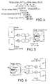
- La figure 4 une organisation de filtres de synthèse permettant de conserver la propriété de reconstruction parfaite des filtres de synthèse lors d'une commutation de filtres.
- La figure 5 un mode de fonctionnement d'un banc de synthèse adaptatif.
- La figure 6 le principe de mise en oeuvre d'un banc d'analyse adaptatif.
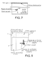
- La figure 7 un mode de positionnement d'un masque d'estimation.
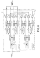
- La figure 8 un mode de réalisation d'un codeur à 4 bandes adaptatif selon l'invention.
- La figure 9 un mode de traitement des bords et d'initialisation des filtres.
- Figure 1 a hierarchical sub-band analysis bench according to the prior art.
- FIG. 2 a structure of a trellis filter bank.
- FIG. 3, an implementation of a device for switching analysis and synthesis filters of a signal broken down into sub-bands.
- FIG. 4 an organization of synthesis filters making it possible to preserve the property of perfect reconstruction of the synthesis filters during a switching of filters.
- Figure 5 an operating mode of an adaptive synthesis bench.
- Figure 6 the principle of implementation of an adaptive analysis bench.
- FIG. 7 a mode of positioning an estimation mask.
- FIG. 8 an embodiment of an adaptive 4-band coder according to the invention.
- FIG. 9 a mode of processing the edges and initializing the filters.
Le filtrage en sous bande fait partie des techniques de décorrélation dite par transformée. Un banc de décomposition en sous bandes est constitué, d'une partie analyse qui effectue une décomposition du signal et d'une partie synthèse qui reconstruit le signal à partir des sous bandes. La décomposition d'un signal en M bandes peut être réalisée soit par un ensemble de filtres montés en parallèle, soit par la mise en cascade de cellules de décomposition à peu de bandes comportant typiquement deux bandes. Dans ce dernier cas, la décomposition hiérarchique du signal est structurée de la manière représentée à la figure 1. La structure arborescente correspondante est formée de cellules d'analyse synthèse à deux bandes encore appelées cellules de décomposition en octaves. Chaque cellule est formée d'un couple de filtres notés H₀ et H₁. Pour conserver un débit global constant, les signaux en sortie des cellules d'analyse sont sous-échantillonnés avec un taux critique R = 2. Les signaux appliqués aux entrées des cellules de synthèse correspondantes, non représentées sont sur-échantillonnés par deux. Une telle structure permet dans le cas de filtrage d'images dont les signaux correspondants sont par nature non stationnaires, d'obtenir un gain appréciable en terme de décorrélation et par suite en termes de codage, si le système d'analyse synthèse a la possibilité de s'adapter aux caractéristiques locales des images. Pour ce type de structure deux possibilités sont à envisager, elles consistent, soit à adapter l'arbre de décomposition, soit à adapter les filtres, l'une n'étant pas exclusive de l'autre. Plutôt que d'adapter l'analyse au signal pour déterminer l'arborescence de décomposition la mieux adaptée au signal pour une paire de filtres H₀ et H₁ déterminée a priori, I'idée de l'invention consiste en une approche complémentaire qui consiste en la détermination d'un procédé d'adaptation des filtres vis à vis des propriétés statistiques du signal d'entrée. Elle concerne plus particulièrement le cas du filtrage d'image par des bancs de décomposition hiérarchique en octave utilisant des filtres séparables. L'utilisation de filtres séparables, où le filtrage est indépendant sur les lignes et les colonnes de l'image, permet de ramener les traitements au cas de signaux monodimensionnels. De plus, seuls les bancs de décomposition assurant la reconstruction parfaite du signal en l'absence de quantification des signaux sous bandes sont à considérer. Deux catégories de filtres permettent d'obtenir ces résultats, ces filtres étant connus sous l'abréviation anglo-saxonne CQF (Conjugated Quadrature Filter) et sous l'appellation de filtres à phase linéaires bi-orthogonaux. Dans les filtres CQF les filtres de fonction de transfert H₀ et H₁ sont des versions retournées l'une de l'autre. Au sein d'une décomposition dyadique, ils correspondent à des ondelettes orthogonales. Parmi les filtres à phase linéaire bi-orthogonaux deux solutions sont également réalisables selon la parité de l'ordre et la symétrie des filtres H₀ et H₁. Ces filtres sont connus, d'une part, sous l'abréviation anglo-saxonne SSEE de "Symetric-Symetric-Even-Even" et ont la propriété d'utiliser des filtres H₀ et H₁ symétriques et d'ordre pair et d'autre part, sous l'abréviation anglo-saxonne SAOO de "Symetric-Antisymetric-Odd-Odd" où les filtres H₀ et H₁ sont respectivement symétriques et anti-symétriques d'ordre impair. Les filtres de type SSEE imposent aux filtres H₀ et H₁ d'être de longueurs différentes. Dans les modes de réalisation de l'invention décrits ci-après seuls les filtres de type CQF et SAOO sont considérés. Les catégories de filtres retenus existent sous une forme transverse et également sous une forme treillis. Les filtres en treillis assurent la reconstruction parfaite du signal indépendamment des valeurs des coefficients. Une structure en treillis généralisée, telle que celle qui est représentée à la figure 2, intègre les deux cas de filtres CQF et SAOO. Sur la figure 2 chaque cellule du treillis du filtre d'analyse Ei est paramétrée par quatre coefficients ai, bi, ci et di formant la matrice de transfert de la cellule. Cette matrice de transfert Ei est représentable sous la forme![]()
![]()
Afin d'éviter une dégénérescence des cellules en treillis il est nécessaire d'imposer que le déterminant de la matrice Ei soit différent de zéro. Pour une facilité de calcul sa valeur est imposée égale à 1. Les treillis de type CQF sont obtenus à partir du treillis généralisé en imposant aux coefficients des cellules Ei de satisfaire les relations ai = di et bi = -ci. De la même manière, les treillis SAOO imposent aux coefficients des cellules Ei, les relations ai = di et bi = ci ainsi que, l'ajout d'une cellule terminale en sortie des filtres dont la matrice de transfert est définie par la relation :![]()
![]()
Dans une optique de compression d'images et de codage compatible de signaux de télévision, les filtres sont optimisés selon un critère qui fait intervenir le coût de codage. Ce dernier, pour deux signaux indépendants de valeur moyenne nulle, est proportionnel au produit des variances des deux signaux. Le critère d'optimisation qui est retenu pour la mise en oeuvre de l'invention est de la forme
où Rij(ℓ) représente l'intercorrélation de retard ℓ entre les signaux i et j en sortie des filtres H₀ et H₁ et après sous-échantillonnage. Les coefficients µ₁, µ₂ et µ₃ permettent de moduler la contribution de chacun des termes. Le premier terme tend à minimiser le coût de codage sous une hypothèse d'indépendance et de blancheur des signaux sous bandes. Le second terme cherche à rendre les deux signaux sous bandes indépendants, pour une décorrélation inter-bandes, et le troisième terme contribue au blanchiment des signaux pour une décorrélation intra-bande (par analogie au spectre d'un bruit blanc).With a view to image compression and compatible coding of television signals, the filters are optimized according to a criterion which involves the cost of coding. The latter, for two independent signals of zero mean value, is proportional to the product of the variances of the two signals. The optimization criterion which is retained for the implementation of the invention is of the form
where R ij (ℓ) represents the delay correlation ℓ between the signals i and j at the output of the filters H₀ and H₁ and after subsampling. The coefficients µ₁, µ₂ and µ₃ allow to modulate the contribution of each of the terms. The first term tends to minimize the cost of coding under the assumption of independence and whiteness of the signals in bands. The second term seeks to make the two signals under independent bands, for an inter-band decorrelation, and the third term contributes to the whitening of the signals for an intra-band decorrelation (by analogy to the spectrum of white noise).
Afin d'éviter une recherche d'optimisation des filtres de décomposition d'un banc de filtrage en sous bandes à partir des statistiques globales du signal, conduisant à des résultats moyens du fait du caractère non stationnaire des images, le procédé selon l'invention consiste à adapter les filtres aux caractéristiques locales de l'image. Ceci impose que les filtres d'analyse soient modifiés au cours du filtrage en fonction des statistiques mesurées dans le voisinage de chaque point courant. Comme par ailleurs le banc de filtrage doit continuer d'assurer la reconstruction parfaite du signal en l'absence de quantification, le problème de la reconstruction parfaite au niveau de la synthèse est résolu en faisant intervenir une dimension supplémentaire qui est le temps. En effet, lorsque les filtres d'analyse sont modifiés, il apparaît une phase transitoire où les échantillons issus de l'ancien et du nouveau filtre sont convolués à la synthèse. Comme le montre le banc de filtre de la figure 3 représenté, un banc de filtrage en deux bandes, dans lesquelles deux jeux de filtres d'analyse [H₀(z),H₁(z)] et [H₀'(z),H₁'(z)] ainsi que deux jeux de filtres de synthèse supplémentaires, [G₀(z),G₁(z)] et [G₀'(z),G₁(z)], peuvent être commutés. En présence de filtres de longueur 4 le problème est résolu comme le montre la figure 4 en utilisant un jeu de filtres de synthèse [G₀''(z),G₁''z)] durant la phase transitoire. Pour simplifier la représentation de la figure 4, les filtres ont été représentés avec une longueur de 4. Le nombre de filtres transitoires est donné par la relation (N/2-1) où N est la longueur des filtres.In order to avoid a search for optimization of the decomposition filters of a sub-band filtering bench from global signal statistics, leading to average results due to the non-stationary nature of the images, the method according to the invention consists in adapting the filters to the local characteristics of the image. This requires that the analysis filters be modified during the filtering as a function of the statistics measured in the vicinity of each current point. As, moreover, the filtering bench must continue to ensure perfect reconstruction of the signal in the absence of quantification, the problem of perfect reconstruction at the level of synthesis is resolved by involving an additional dimension which is time. Indeed, when the analysis filters are modified, a transient phase appears where the samples from the old and the new filter are combined for synthesis. As shown in the filter bank of FIG. 3 represented, a filter bank in two bands, in which two sets of analysis filters [H₀ (z), H₁ (z)] and [H₀ '(z), H₁ '(z)] as well as two additional synthesis filter sets, [G₀ (z), G₁ (z)] and [G₀' (z), G₁ (z)], can be switched. In the presence of filters of length 4 the problem is solved as shown in FIG. 4 by using a set of synthesis filters [G₀ '' (z), G₁''z)] during the transient phase. To simplify the representation of FIG. 4, the filters have been represented with a length of 4. The number of transient filters is given by the relation (N / 2-1) where N is the length of the filters.
Hors de la phase de transition, les filtres d'analyse et de synthèse sont liés par la relation classique :
Lorsque les filtres sont implantés sous la forme de treillis, le problème de la commutation des filtres se résout directement. Il suffit pour cela d'observer le mécanisme de la propagation de l'information à travers la structure du treillis. Dans ce cas, les coefficients des cellules peuvent être modifiés de manière quelconque à l'analyse sous réserve que cette modification soit répercutée à la synthèse à un instant approprié. La reconstruction parfaite est alors toujours assurée dès lors que le produit matriciel![]()
est respecté
où Ei et Fi représentent respectivement les matrices de transfert des filtres d'analyse et de synthèse et I la matrice identité.When the filters are installed in the form of a trellis, the problem of switching the filters is directly resolved. It suffices to observe the mechanism of the propagation of information through the lattice structure. In this case, the coefficients of the cells can be modified in any way upon analysis, provided that this modification be reflected in the summary at an appropriate time. Perfect reconstruction is then always ensured as soon as the matrix product ![]()
is respected
where E i and F i respectively represent the transfer matrices of the analysis and synthesis filters and I the identity matrix.
Plus précisément, si les coefficients de chaque cellule Ei sont modifiés à un instant n, ce temps étant compté après sous-échantillonnage, la propriété de reconstruction parfaite est conservée à condition que les coefficients de la cellule de synthèse correspondante Fi soient mis à jour à l'instant n+L-1-i, L représentant le nombre total de cellules du treillis. Le retard est apporté par les cellules du treillis situées entre Ei et Fi.More precisely, if the coefficients of each cell E i are modified at an instant n, this time being counted after subsampling, the property of perfect reconstruction is preserved on condition that the coefficients of the corresponding synthesis cell F i are set to day at time n + L-1-i, L representing the total number of cells in the trellis. The delay is provided by the trellis cells located between E i and F i .
L'optimisation du critère dans le cas des filtres de type CQF est réalisée par l'algorithme connu de Newton. La convergence peut être améliorée en modifiant l'algorithme par la méthode de Levenberg-Marquardt. L'optimisation dans le cas des treillis de type SAOO et du treillis généralisé est réalisée sous contrainte et elle est confiée à l'algorithme de Lagrange-Newton. Les matrices de corrélation des signaux nécessaires au calcul sont obtenues par récurrence sur l'ordre du treillis et peuvent être exprimées en fonction des signaux à l'entrée de chaque cellule de filtrage à optimiser.The optimization of the criterion in the case of filters of the CQF type is carried out by the algorithm known to Newton. Convergence can be improved by modifying the algorithm by the Levenberg-Marquardt method. Optimization in the case of SAOO type lattices and generalized lattices is carried out under constraint and is entrusted to the Lagrange-Newton algorithm. The signal correlation matrices necessary for the calculation are obtained by induction on the order of the trellis and can be expressed as a function of the signals at the input of each filter cell to be optimized.
L'algorithme de Newton nécessite une bonne initialisation des filtres. Celle-ci est donnée au départ par un jeu de filtres déterminés a priori utilisés dans une décomposition en sous bandes classique. En cours de filtrage, le couple de filtres calculés pour le point précédent sert d'initialisation de l'algorithme pour le calcul du point courant. Ceci permet, d'assurer une convergence plus rapide de l'algorithme et d'obtenir des coefficients de filtres qui minimisent le critère selon la relation (3) décrite précédemment. Du fait que, les filtres d'analyse peuvent être modifiés à chaque point après sous échantillonnage de l'image à l'entrée de la cellule de filtre à optimiser, et que la transmission vers le décodeur des coefficients des filtres d'analyse indispensables au calcul des filtres de synthèse entraînerait un surcoût prohibitif, le procédé selon l'invention met en oeuvre une technique qui permet de recalculer automatiquement les filtres de synthèse au décodeur. Selon l'invention, les propriétés statistiques du signal à l'entrée de la cellule à optimiser sont estimées à partir d'un masque de points. En l'absence de quantification, les filtres de synthèse peuvent alors être recalculés sur le signal reconstruit comme le montre la figure 5 où le même masque MQ de points que celui qui est employé pour le calcul des filtres d'analyse est utilisé, dans la mesure où il est possible de disposer déjà des points correspondants reconstruits. Pour cela, il est indispensable de placer le masque d'estimation correctement au niveau de l'analyse pour prendre en compte le retard apporté par le banc de filtres comme cela est représenté à la figure 6. Dans ces conditions, si en désignant par L le nombre de cellules du treillis des filtres utilisés dans le banc de décomposition et par M le nombre de niveaux sur la branche la plus découpée, le retard global apporté par le banc est donné par la relation :![]()
![]()
Comme ce retard peut devenir important lorsque la découpe en sous bande est profonde ou lorsque les longueurs des filtres augmentent, le masque des points nécessaire à l'estimation des statistiques pour l'optimisation des filtres, risque de se trouver éloigner du point à filtrer. Le retard D calculé précédemment correspond au retard maximum entre le point filtré et le masque d'estimation. Pour les niveaux intermédiaires dans l'arbre, ce retard est moindre. Afin de conserver à l'optimisation un caractère local, il est préférable de choisir, comme le montre la figure 7 d'extraire le masque MQ des lignes ou des colonnes précédentes situées au dessus, à gauche du point courant N à filtrer.As this delay can become significant when the cut in sub-band is deep or when the lengths of the filters increase, the mask of the points necessary for the estimation of the statistics for the optimization of the filters, is likely to be distant from the point to be filtered. The delay D calculated previously corresponds to the maximum delay between the filtered point and the estimation mask. For the intermediate levels in the tree, this delay is less. In order to keep the local character of the optimization, it is preferable to choose, as shown in Figure 7, to extract the mask MQ from the preceding rows or columns located above, to the left of the current point N to be filtered.
Il est à noter que tant que les points du masque d'estimation ne sont pas disponibles à l'analyse, c'est-à-dire à l'initialisation à cause du retard apporté par le banc de filtres, un jeu de filtres déterminé a priori et connus du codeur et du décodeur doit être utilisé.It should be noted that as long as the points of the estimation mask are not available for analysis, that is to say at initialization because of the delay provided by the filter bank, a determined set of filters a priori and known to the coder and the decoder must be used.
En présence de quantification le produit des matrices de transfert Ei et Fi de chaque couple de cellules d'analyse et de synthèse doit vérifier constamment l'identité, toute erreur sur l'un des coefficients d'une des deux cellules entraînant nécessairement une erreur de reconstruction sur le signal. Du fait que les structures en treillis sont très sensibles à ces erreurs et que, lorsque les signaux sous bande sont quantifiés les filtres de synthèse sont recalculés sur le signal reconstruit à partir des signaux quantifiés, le produit des matrices Ei et Fi ne peut plus respecter l'identité. Dans ces conditions une dérive au niveau du recalcul des filtres de synthèse due à l'erreur de quantification apparaît. Pour éviter ce phénomène, les filtres d'analyse et de synthèse sont calculés selon l'invention sur le même signal puisque le masque de points nécessaire au calcul des filtres d'analyse est extrait, comme le montre la figure 8, du signal reconstruit localement au codeur.In the presence of quantification, the product of the transfer matrices E i and F i of each pair of analysis and synthesis cells must constantly verify the identity, any error on one of the coefficients of one of the two cells necessarily resulting in a reconstruction error on the signal. Because the lattice structures are very sensitive to these errors and that, when the subband signals are quantized the synthesis filters are recalculated on the signal reconstructed from the quantized signals, the product of the matrices E i and F i cannot no longer respect identity. Under these conditions, a drift in the recalculation of the synthesis filters due to the quantification error appears. To avoid this phenomenon, the filters analysis and synthesis are calculated according to the invention on the same signal since the mask of points necessary for the calculation of the analysis filters is extracted, as shown in FIG. 8, from the signal reconstructed locally at the coder.
A cette fin, il est adjoint aux filtres H₀(z) H₁(z) de l'arbre de décomposition en sous bande du codeur, représenté à l'intérieur d'une ligne fermée en pointillé 1 sur la figure 8, un arbre de reconstruction composé des filtres de synthèse G₀(z) et G₁(z) représentés également à l'intérieur d'une ligne fermée en pointillé 2 formant un décodeur local. Les coefficients des filtres sont calculés par un ou plusieurs microprocesseurs 3₁ ... 3₆ recevant le signal appliqué à chaque entrée des filtres. Les processeurs correspondant sont programmés pour effectuer le calcul des coefficients selon le critère d'optimisation défini par la relation (3). L'arbre de décomposition de la figure 8 convient pour un filtrage adaptatif d'un signal de télévision par exemple à 4 sous bandes. En vue de la transmission des signaux sous bandes des quantificateurs 4₁ à 4₄ sont placés à la sortie des bancs de filtres pour quantifier chaque sous bande.To this end, there is added to the filters H₀ (z) H₁ (z) of the decomposition tree in sub-band of the coder, represented inside a closed line in
Des circuits de déquantification 5₁ à 5₄ correspondants sont placés aux entrées des bancs de filtres de l'arbre de reconstruction du décodeur local 2.Corresponding dequantification circuits 5₁ to 5₄ are placed at the inputs of the filter banks of the reconstruction tree of the
Il est à noter que le masque de points doit impérativement être extrait dans l'environnement causal du point à filtrer tant au codeur qu'au décodeur. D'autre part, certaines parties de l'image doivent être filtrées avec des filtres connus du codeur 1 et du décodeur 2 pour les traitements à l'initialisation et sur le bord supérieur et le bord gauche de l'image. Dans le cas de l'implantation à 4 sous bandes selon la figure 8 cela se traduit sur la figure 9 par l'apparition de zones 6, 7 et 8. En utilisant des filtres CQF le traitement des bords pourra être effectué de façon connue par périodisation circulaire.It should be noted that the point mask must imperatively be extracted in the causal environment of the point to be filtered both at the coder and at the decoder. On the other hand, certain parts of the image must be filtered with filters known to the
Naturellement, l'invention n'est pas limitée aux exemples décrits, d'autres modes de réalisation sont également envisageables consistant par exemple à regrouper dans un seul et même processeur les calculs nécessaires à l'optimisation des filtres.Naturally, the invention is not limited to the examples described, other embodiments can also be envisaged, consisting for example in grouping in a single processor the calculations necessary for optimizing the filters.
Claims (11)
Applications Claiming Priority (2)
| Application Number | Priority Date | Filing Date | Title |
|---|---|---|---|
| FR9400633 | 1994-01-21 | ||
| FR9400633A FR2715527B1 (en) | 1994-01-21 | 1994-01-21 | Method and device for analysis and synthesis in adaptive sub-bands. |
Publications (2)
| Publication Number | Publication Date |
|---|---|
| EP0664652A1 true EP0664652A1 (en) | 1995-07-26 |
| EP0664652B1 EP0664652B1 (en) | 1999-09-15 |
Family
ID=9459253
Family Applications (1)
| Application Number | Title | Priority Date | Filing Date |
|---|---|---|---|
| EP95400069A Expired - Lifetime EP0664652B1 (en) | 1994-01-21 | 1995-01-13 | Method and apparatus for adaptive subband analysis and synthesis |
Country Status (4)
| Country | Link |
|---|---|
| US (1) | US5844610A (en) |
| EP (1) | EP0664652B1 (en) |
| DE (1) | DE69512099T2 (en) |
| FR (1) | FR2715527B1 (en) |
Cited By (2)
| Publication number | Priority date | Publication date | Assignee | Title |
|---|---|---|---|---|
| FR2796506A1 (en) * | 1999-07-13 | 2001-01-19 | Canon Kk | Method for filtering of digital signals, adapted to data and to memory constraints |
| FR2887711A1 (en) * | 2005-06-23 | 2006-12-29 | Thomson Licensing Sa | METHOD OF ENCODING AND HIERARCHICAL DECODING |
Families Citing this family (10)
| Publication number | Priority date | Publication date | Assignee | Title |
|---|---|---|---|---|
| US6757326B1 (en) * | 1998-12-28 | 2004-06-29 | Motorola, Inc. | Method and apparatus for implementing wavelet filters in a digital system |
| FR2790168A1 (en) * | 1999-02-24 | 2000-08-25 | Canon Kk | Digital signal transformation method, in which signal is processed by successive samples, such that calculations made on any series do not take into account samples in following series, and any series terminates in low frequency sample |
| EP1032216A1 (en) * | 1999-02-24 | 2000-08-30 | Canon Kabushiki Kaisha | Device and method for transforming a digital signal. |
| FR2790172A1 (en) * | 1999-02-24 | 2000-08-25 | Canon Kk | Digital signal transformation method, in which signal is processed by successive samples, such that calculations made on any series do not take into account samples in following series, and any series terminates in low frequency sample |
| FR2790173A1 (en) * | 1999-02-24 | 2000-08-25 | Canon Kk | DIGITAL SIGNAL TRANSFORMATION DEVICE AND METHOD |
| FR2790171A1 (en) * | 1999-02-24 | 2000-08-25 | Canon Kk | Digital signal transformation method, in which signal is processed by successive samples, such that calculations made on any series do not take into account samples in following series, and any series terminates in low frequency sample |
| AU2003272833A1 (en) * | 2002-09-17 | 2004-04-08 | Vladimir Ceperkovic | Fast codec with high compression ratio and minimum required resources |
| SE0301273D0 (en) * | 2003-04-30 | 2003-04-30 | Coding Technologies Sweden Ab | Advanced processing based on a complex exponential-modulated filter bank and adaptive time signaling methods |
| US8958510B1 (en) * | 2010-06-10 | 2015-02-17 | Fredric J. Harris | Selectable bandwidth filter |
| US20120195367A1 (en) * | 2011-01-14 | 2012-08-02 | Ebrisk Video Inc. | Adaptive loop filtering using tables of filter sets for video coding |
Citations (3)
| Publication number | Priority date | Publication date | Assignee | Title |
|---|---|---|---|---|
| FR2643531A1 (en) * | 1989-02-21 | 1990-08-24 | Thomson Csf | METHOD AND APPARATUS FOR COMPRESSION OF INFORMATION FOR COMPATIBLE DECODING OF A FAMILY OF TELEVISION SIGNALS OF GROWING RESOLUTIONS |
| US4969040A (en) * | 1989-10-26 | 1990-11-06 | Bell Communications Research, Inc. | Apparatus and method for differential sub-band coding of video signals |
| FR2654887A1 (en) * | 1989-11-20 | 1991-05-24 | Thomson Csf | Compatible coding and uncoding method and device for television images of different resolutions |
Family Cites Families (7)
| Publication number | Priority date | Publication date | Assignee | Title |
|---|---|---|---|---|
| US5122873A (en) * | 1987-10-05 | 1992-06-16 | Intel Corporation | Method and apparatus for selectively encoding and decoding a digital motion video signal at multiple resolution levels |
| US5218435A (en) * | 1991-02-20 | 1993-06-08 | Massachusetts Institute Of Technology | Digital advanced television systems |
| FR2677836B1 (en) * | 1991-06-11 | 1997-08-29 | Thomson Csf | ENCODER-DECODER UNDER BANDS OF TELEVISION SIGNALS AT DIFFERENT COMPATIBILITY LEVELS. |
| FR2680924B1 (en) * | 1991-09-03 | 1997-06-06 | France Telecom | FILTERING METHOD SUITABLE FOR A SIGNAL TRANSFORMED INTO SUB-BANDS, AND CORRESPONDING FILTERING DEVICE. |
| GB2263373B (en) * | 1992-01-09 | 1995-05-24 | Sony Broadcast & Communication | Data error concealment |
| US5469517A (en) * | 1992-01-21 | 1995-11-21 | Nec Corporation | Motion compensation circuit |
| CA2088082C (en) * | 1992-02-07 | 1999-01-19 | John Hartung | Dynamic bit allocation for three-dimensional subband video coding |
-
1994
- 1994-01-21 FR FR9400633A patent/FR2715527B1/en not_active Expired - Fee Related
-
1995
- 1995-01-13 DE DE69512099T patent/DE69512099T2/en not_active Expired - Lifetime
- 1995-01-13 EP EP95400069A patent/EP0664652B1/en not_active Expired - Lifetime
- 1995-01-20 US US08/375,737 patent/US5844610A/en not_active Expired - Lifetime
Patent Citations (3)
| Publication number | Priority date | Publication date | Assignee | Title |
|---|---|---|---|---|
| FR2643531A1 (en) * | 1989-02-21 | 1990-08-24 | Thomson Csf | METHOD AND APPARATUS FOR COMPRESSION OF INFORMATION FOR COMPATIBLE DECODING OF A FAMILY OF TELEVISION SIGNALS OF GROWING RESOLUTIONS |
| US4969040A (en) * | 1989-10-26 | 1990-11-06 | Bell Communications Research, Inc. | Apparatus and method for differential sub-band coding of video signals |
| FR2654887A1 (en) * | 1989-11-20 | 1991-05-24 | Thomson Csf | Compatible coding and uncoding method and device for television images of different resolutions |
Non-Patent Citations (1)
| Title |
|---|
| PETRAGLIA ET AL.: "Performance Analysis of Adaptive Filter Structures Based on Subband Decomposition", 1993 IEEE INTERNATIONAL SYMPOSIUM ON CIRCUITS AND SYSTEMS, 3 May 1993 (1993-05-03), CHICAGO, pages 60 - 63, XP010115102, DOI: doi:10.1109/ISCAS.1993.393657 * |
Cited By (4)
| Publication number | Priority date | Publication date | Assignee | Title |
|---|---|---|---|---|
| FR2796506A1 (en) * | 1999-07-13 | 2001-01-19 | Canon Kk | Method for filtering of digital signals, adapted to data and to memory constraints |
| FR2887711A1 (en) * | 2005-06-23 | 2006-12-29 | Thomson Licensing Sa | METHOD OF ENCODING AND HIERARCHICAL DECODING |
| EP1737241A3 (en) * | 2005-06-23 | 2009-10-21 | THOMSON Licensing | Hierarchical coding and decoding method |
| US7848429B2 (en) | 2005-06-23 | 2010-12-07 | Thomson Licensing | Hierarchical coding and decoding method |
Also Published As
| Publication number | Publication date |
|---|---|
| US5844610A (en) | 1998-12-01 |
| FR2715527A1 (en) | 1995-07-28 |
| DE69512099T2 (en) | 2000-03-02 |
| EP0664652B1 (en) | 1999-09-15 |
| FR2715527B1 (en) | 1996-02-23 |
| DE69512099D1 (en) | 1999-10-21 |
Similar Documents
| Publication | Publication Date | Title |
|---|---|---|
| EP0664652B1 (en) | Method and apparatus for adaptive subband analysis and synthesis | |
| EP1989706B1 (en) | Device for perceptual weighting in audio encoding/decoding | |
| EP1794748B1 (en) | Data processing method by passage between different sub-band domains | |
| EP0542974B1 (en) | Variable resolution level television signal subband CODEC. | |
| EP3330964B1 (en) | Resampling of an audio signal for encoding/decoding with low delay | |
| EP0608174A1 (en) | System for predictive encoding/decoding of a digital speech signal by an adaptive transform with embedded codes | |
| FR2628918A1 (en) | ECHO CANCELER WITH FREQUENCY SUB-BAND FILTERING | |
| CA2841303C (en) | Adaptations of analysis or synthesis weighting windows for transform coding or decoding | |
| EP2104936A2 (en) | Low-delay transform coding using weighting windows | |
| EP0511095B1 (en) | Coding and decoding method and apparatus for a digital signal | |
| EP0506535B1 (en) | Method and system for processing of pre-echos of a frequency transform coded digital audio signal | |
| EP2232489B1 (en) | Transform-based coding/decoding, with adaptive windows | |
| FR3009121A1 (en) | METHOD OF SUPPRESSING LATE REVERBERATION OF A SOUND SIGNAL | |
| EP2656344B1 (en) | Improved filtering in the transformed domain | |
| EP0285495B1 (en) | Digital signal processing system using a filter bank | |
| FR2667745A1 (en) | Method of synthesising sub-band filters with quantised coefficients and filter structures obtained by this method | |
| FR2661062A2 (en) | Method and device for compatible coding and decoding of television images with different resolutions | |
| FR2731855A1 (en) | INVERSIBLE METHOD OF COMPLEX FREQUENCY DECOMPOSITION OF A DIGITAL SIGNAL AND ITS APPLICATION TO A DEVICE FOR REDUCING THE INFORMATION FLOW OF AUDIONUMERIC SIGNALS | |
| FR2673795A1 (en) | Method and device for matched interpolation of subband signals for compatible inter-image coding of television signals | |
| EP0763892B1 (en) | Perfect reconstruction lattice filter bank | |
| Vetterli | Analyse, synthèse et complexité de calcul de bancs de filtres numériques | |
| FR2771543A1 (en) | Noise reduction algorithm | |
| FR2773653A1 (en) | Input sound digital word decoding/coding device, especially for analyzing and compressing inputs for recording | |
| FR2853804A1 (en) | Audio signal decoding process, involves constructing uncorrelated signal from audio signals based on audio signal frequency transformation, and joining audio and uncorrelated signals to generate signal representing acoustic scene | |
| CA2291866A1 (en) | Process for compressing images by wavelet transform using successive approximation quantization technique |
Legal Events
| Date | Code | Title | Description |
|---|---|---|---|
| PUAI | Public reference made under article 153(3) epc to a published international application that has entered the european phase |
Free format text: ORIGINAL CODE: 0009012 |
|
| AK | Designated contracting states |
Kind code of ref document: A1 Designated state(s): DE GB IT NL |
|
| 17P | Request for examination filed |
Effective date: 19960119 |
|
| RAP1 | Party data changed (applicant data changed or rights of an application transferred) |
Owner name: THOMSON MULTIMEDIA |
|
| 17Q | First examination report despatched |
Effective date: 19980120 |
|
| RAP1 | Party data changed (applicant data changed or rights of an application transferred) |
Owner name: THOMSON MULTIMEDIA |
|
| GRAG | Despatch of communication of intention to grant |
Free format text: ORIGINAL CODE: EPIDOS AGRA |
|
| GRAG | Despatch of communication of intention to grant |
Free format text: ORIGINAL CODE: EPIDOS AGRA |
|
| GRAH | Despatch of communication of intention to grant a patent |
Free format text: ORIGINAL CODE: EPIDOS IGRA |
|
| GRAH | Despatch of communication of intention to grant a patent |
Free format text: ORIGINAL CODE: EPIDOS IGRA |
|
| GRAA | (expected) grant |
Free format text: ORIGINAL CODE: 0009210 |
|
| AK | Designated contracting states |
Kind code of ref document: B1 Designated state(s): DE GB IT NL |
|
| REF | Corresponds to: |
Ref document number: 69512099 Country of ref document: DE Date of ref document: 19991021 |
|
| ITF | It: translation for a ep patent filed | ||
| GBT | Gb: translation of ep patent filed (gb section 77(6)(a)/1977) |
Effective date: 20000111 |
|
| PLBE | No opposition filed within time limit |
Free format text: ORIGINAL CODE: 0009261 |
|
| STAA | Information on the status of an ep patent application or granted ep patent |
Free format text: STATUS: NO OPPOSITION FILED WITHIN TIME LIMIT |
|
| 26N | No opposition filed | ||
| REG | Reference to a national code |
Ref country code: GB Ref legal event code: 746 Effective date: 20011126 |
|
| REG | Reference to a national code |
Ref country code: GB Ref legal event code: IF02 |
|
| REG | Reference to a national code |
Ref country code: DE Ref legal event code: R082 Ref document number: 69512099 Country of ref document: DE Representative=s name: MANFRED ROSSMANITH, DE |
|
| REG | Reference to a national code |
Ref country code: DE Ref legal event code: R082 Ref document number: 69512099 Country of ref document: DE Representative=s name: ROSSMANITH, MANFRED, DIPL.-PHYS. DR.RER.NAT., DE Effective date: 20120111 Ref country code: DE Ref legal event code: R081 Ref document number: 69512099 Country of ref document: DE Owner name: THOMSON LICENSING, FR Free format text: FORMER OWNER: THOMSON MULTIMEDIA, BOULOGNE, FR Effective date: 20120111 |
|
| PGFP | Annual fee paid to national office [announced via postgrant information from national office to epo] |
Ref country code: IT Payment date: 20120118 Year of fee payment: 18 |
|
| PGFP | Annual fee paid to national office [announced via postgrant information from national office to epo] |
Ref country code: DE Payment date: 20130117 Year of fee payment: 19 Ref country code: GB Payment date: 20130121 Year of fee payment: 19 |
|
| PGFP | Annual fee paid to national office [announced via postgrant information from national office to epo] |
Ref country code: NL Payment date: 20130110 Year of fee payment: 19 |
|
| REG | Reference to a national code |
Ref country code: DE Ref legal event code: R119 Ref document number: 69512099 Country of ref document: DE |
|
| REG | Reference to a national code |
Ref country code: NL Ref legal event code: V1 Effective date: 20140801 |
|
| GBPC | Gb: european patent ceased through non-payment of renewal fee |
Effective date: 20140113 |
|
| REG | Reference to a national code |
Ref country code: DE Ref legal event code: R119 Ref document number: 69512099 Country of ref document: DE Effective date: 20140801 |
|
| PG25 | Lapsed in a contracting state [announced via postgrant information from national office to epo] |
Ref country code: DE Free format text: LAPSE BECAUSE OF NON-PAYMENT OF DUE FEES Effective date: 20140801 Ref country code: NL Free format text: LAPSE BECAUSE OF NON-PAYMENT OF DUE FEES Effective date: 20140801 |
|
| PG25 | Lapsed in a contracting state [announced via postgrant information from national office to epo] |
Ref country code: GB Free format text: LAPSE BECAUSE OF NON-PAYMENT OF DUE FEES Effective date: 20140113 |
|
| PG25 | Lapsed in a contracting state [announced via postgrant information from national office to epo] |
Ref country code: IT Free format text: LAPSE BECAUSE OF NON-PAYMENT OF DUE FEES Effective date: 20140113 |