EP0664421B2 - Gas control valve - Google Patents
Gas control valve Download PDFInfo
- Publication number
- EP0664421B2 EP0664421B2 EP19940630072 EP94630072A EP0664421B2 EP 0664421 B2 EP0664421 B2 EP 0664421B2 EP 19940630072 EP19940630072 EP 19940630072 EP 94630072 A EP94630072 A EP 94630072A EP 0664421 B2 EP0664421 B2 EP 0664421B2
- Authority
- EP
- European Patent Office
- Prior art keywords
- valve
- gas
- control valve
- valve body
- shutoff
- Prior art date
- Legal status (The legal status is an assumption and is not a legal conclusion. Google has not performed a legal analysis and makes no representation as to the accuracy of the status listed.)
- Expired - Lifetime
Links
Images
Classifications
-
- F—MECHANICAL ENGINEERING; LIGHTING; HEATING; WEAPONS; BLASTING
- F16—ENGINEERING ELEMENTS AND UNITS; GENERAL MEASURES FOR PRODUCING AND MAINTAINING EFFECTIVE FUNCTIONING OF MACHINES OR INSTALLATIONS; THERMAL INSULATION IN GENERAL
- F16K—VALVES; TAPS; COCKS; ACTUATING-FLOATS; DEVICES FOR VENTING OR AERATING
- F16K31/00—Actuating devices; Operating means; Releasing devices
-
- F—MECHANICAL ENGINEERING; LIGHTING; HEATING; WEAPONS; BLASTING
- F23—COMBUSTION APPARATUS; COMBUSTION PROCESSES
- F23N—REGULATING OR CONTROLLING COMBUSTION
- F23N1/00—Regulating fuel supply
- F23N1/005—Regulating fuel supply using electrical or electromechanical means
-
- F—MECHANICAL ENGINEERING; LIGHTING; HEATING; WEAPONS; BLASTING
- F16—ENGINEERING ELEMENTS AND UNITS; GENERAL MEASURES FOR PRODUCING AND MAINTAINING EFFECTIVE FUNCTIONING OF MACHINES OR INSTALLATIONS; THERMAL INSULATION IN GENERAL
- F16K—VALVES; TAPS; COCKS; ACTUATING-FLOATS; DEVICES FOR VENTING OR AERATING
- F16K17/00—Safety valves; Equalising valves, e.g. pressure relief valves
- F16K17/36—Safety valves; Equalising valves, e.g. pressure relief valves actuated in consequence of extraneous circumstances, e.g. shock, change of position
- F16K17/38—Safety valves; Equalising valves, e.g. pressure relief valves actuated in consequence of extraneous circumstances, e.g. shock, change of position of excessive temperature
-
- F—MECHANICAL ENGINEERING; LIGHTING; HEATING; WEAPONS; BLASTING
- F23—COMBUSTION APPARATUS; COMBUSTION PROCESSES
- F23N—REGULATING OR CONTROLLING COMBUSTION
- F23N2235/00—Valves, nozzles or pumps
- F23N2235/12—Fuel valves
-
- F—MECHANICAL ENGINEERING; LIGHTING; HEATING; WEAPONS; BLASTING
- F23—COMBUSTION APPARATUS; COMBUSTION PROCESSES
- F23N—REGULATING OR CONTROLLING COMBUSTION
- F23N2235/00—Valves, nozzles or pumps
- F23N2235/12—Fuel valves
- F23N2235/14—Fuel valves electromagnetically operated
-
- F—MECHANICAL ENGINEERING; LIGHTING; HEATING; WEAPONS; BLASTING
- F23—COMBUSTION APPARATUS; COMBUSTION PROCESSES
- F23N—REGULATING OR CONTROLLING COMBUSTION
- F23N2235/00—Valves, nozzles or pumps
- F23N2235/12—Fuel valves
- F23N2235/16—Fuel valves variable flow or proportional valves
-
- F—MECHANICAL ENGINEERING; LIGHTING; HEATING; WEAPONS; BLASTING
- F23—COMBUSTION APPARATUS; COMBUSTION PROCESSES
- F23N—REGULATING OR CONTROLLING COMBUSTION
- F23N2235/00—Valves, nozzles or pumps
- F23N2235/12—Fuel valves
- F23N2235/18—Groups of two or more valves
-
- F—MECHANICAL ENGINEERING; LIGHTING; HEATING; WEAPONS; BLASTING
- F23—COMBUSTION APPARATUS; COMBUSTION PROCESSES
- F23N—REGULATING OR CONTROLLING COMBUSTION
- F23N2235/00—Valves, nozzles or pumps
- F23N2235/12—Fuel valves
- F23N2235/24—Valve details
-
- Y—GENERAL TAGGING OF NEW TECHNOLOGICAL DEVELOPMENTS; GENERAL TAGGING OF CROSS-SECTIONAL TECHNOLOGIES SPANNING OVER SEVERAL SECTIONS OF THE IPC; TECHNICAL SUBJECTS COVERED BY FORMER USPC CROSS-REFERENCE ART COLLECTIONS [XRACs] AND DIGESTS
- Y10—TECHNICAL SUBJECTS COVERED BY FORMER USPC
- Y10T—TECHNICAL SUBJECTS COVERED BY FORMER US CLASSIFICATION
- Y10T137/00—Fluid handling
- Y10T137/1624—Destructible or deformable element controlled
- Y10T137/1797—Heat destructible or fusible
- Y10T137/1819—Safety cut-off
-
- Y—GENERAL TAGGING OF NEW TECHNOLOGICAL DEVELOPMENTS; GENERAL TAGGING OF CROSS-SECTIONAL TECHNOLOGIES SPANNING OVER SEVERAL SECTIONS OF THE IPC; TECHNICAL SUBJECTS COVERED BY FORMER USPC CROSS-REFERENCE ART COLLECTIONS [XRACs] AND DIGESTS
- Y10—TECHNICAL SUBJECTS COVERED BY FORMER USPC
- Y10T—TECHNICAL SUBJECTS COVERED BY FORMER US CLASSIFICATION
- Y10T137/00—Fluid handling
- Y10T137/8593—Systems
- Y10T137/87917—Flow path with serial valves and/or closures
Definitions
- the outlet port of the valve body is adapted to co-operate with a gas burner.
- the outlet port is provided with a metallic insert which receives a burner orifice screw and which is adapted to be connected to an inlet portion of a gas burner.
- the inlet port of valve body is connected to a thermally responsive shutoff valve which, in turn, is adapted to be connected to a gas source.
- the shutoff valve is provided with a metallic valve body and a thermally responsive valve means controlling the flow of gas through a passageway from the gas source to the inlet port of the gas control valve.
- the gas valve of this invention comprises the combination of an electrically operated control valve indicated generally at 12 and a thermally responsive shutoff valve indicated generally at 14.
- Control valve 12 and shutoff valve 14 are detachably connected to each other by means to be hereinafter described.
- combined valves 12 and 14 are utilized to control the flow of gas from a gas source (not shown) to a burner, shown partially at 15, in a gas-fired clothes dryer.
- a lower portion 32 of a metallic valve stem 34 is provided with a rubber O-ring 36 which cooperates with passageway 28 so as to control the flow of gas, in an on and off manner, between inlet opening 18 and outlet opening 22.
- Passageway 28 and part of the lower portion 32 of valve stem 34 are similarly tapered so as to provide an adequate metal-to-metal gas seal in the event O-ring 36 should be damaged or destroyed.
- O-ring 36 could be damaged or destroyed due to exposure to an abnormally high temperature and/or flame which could exist, for example, due to a fire in the dwelling in which the clothes dryer utilizing shutoff valve 14 is located.
- valve stem 34 An upper portion 38 of valve stem 34 is slidably received in a metallic tube 40.
- a disc 42 and a spring 44 Secured in an upper closed end of tube 40 by a disc 42 and a spring 44 is a small mass 46 of a eutectic material.
- Disc 42 is hexagonally shaped on its outer periphery so as to enable the mass 46 of eutectic material, when it is melted, to flow downwardly between the periphery of disc 42 and the inside wall surface of tube 40.
- a spring 48 is nested at one end on a shoulder 50 between passageways 24 and 26, and at its other end around a downwardly extending boss 52 of valve stem 34. Spring 48 is effective to provide a closing bias to valve stem 34.
- An O-ring 54 surrounds tube 40 in a snug fit and is compressed in a recess 56 extending downwardly from a top surface 58 of valve body 16 so as to prevent gas from escaping from outlet opening 22 past tube 40.
- O-ring 54 is secured therein by a washer 60 which is staked to valve body 16 at 62.
- a knob 64 is attached by a stud 66 to valve body 16.
- Stud 66 includes a stepped upper portion 68 cooperative with a stepped opening 70 in knob 64 so as to enable rotation of knob 64 around stud 66 when stud 66 is secured to valve body 16.
- Stud 66 includes a lower knurled portion 72 which is secured in an opening 74 of valve body 16.
- Knob 64 is provided with a cam surface 76 which cooperates with the upper closed end of tube 40 so as to adjust the position of valve stem 34. As shown in Fig. 3, the periphery of knob 64 is circular except for a small straight portion 78.
- valve body 16 includes an integral flange 80 adapted to be secured by any convenient means (not shown) to a surface 82 of the clothes dryer chassis.
- Valve body 16 further includes a tapered surface 84 surrounding its outlet opening 22, and a pair of tabs 86 extending outwardly from tapered surface 84 and toward each other.
- Control valve 12 comprises a plurality of parts made of the same polymeric material, preferably a polyphenylene sulfide (PPS) compound.
- control valve 12 includes a valve body comprised of a middle body portion 88, an upper body portion 90 and a lower body portion 92, all made of the same PPS compound.
- Control valve 12 further includes a coil cover 94 and regulator covers 96 and 98 also made of the same PPS compound.
- Middle body portion 88 is provided with an inlet opening 100 which is aligned with outlet opening 22 of valve body 16.
- Body portion 88 includes a tapered surface 102 surrounding its inlet opening 100, which tapered surface 102 is positioned tightly against tapered surface 84 of valve body 16 by tabs 86, shown in Fig. 3, when shutoff valve 14 and control valve 12 are connected together.
- An O-ring 104 is adapted to be compressed in a recess 106 extending inwardly from tapered surface 102 of body portion 88 so as to prevent gas from escaping to atmosphere at the connection of tapered surfaces 84 and 102.
- Middle body portion 88 is provided with an outlet opening 108.
- a metallic sleeve 110 is insert-molded into outlet opening 108.
- Sleeve 110 has an opening 112 therethrough.
- An orifice screw 114 is threadedly engaged to sleeve 110 at one end of opening 112.
- the outer surface of sleeve 110 is provided with a plurality of grooves 116.
- the grooved surface provides a convenient means for attaching burner 15 and provides a means for dissipating heat in the event that burner flame should exist at or near the orifice screw 114. For example, a low gas pressure condition could cause the burner flame to "burn back" at orifice screw 114. Such heat dissipation prevents body portion 88 from reaching a temperature at which it would become structurally unstable.
- Middle body portion 88 is joined to upper body portion 90 to define chambers 120 and 122, and to lower body portion 92 to define chamber 124.
- Middle body portion 88 is provided with an upwardly extending ledge 126 which extends in a continuous loop around chambers 120 and 122. Ledge 126 is received in a groove 128 of upper body portion 90.
- a gasket 130 shown in Fig. 4, is positioned in groove 128.
- Gasket 130 is made of a metal-filled PPS compound.
- gasket 130 melts, forming an adhesive 131, shown more clearly in Fig. 5, which provides a gas-tight seal and a structurally strong joint between body portions 88 and 90.
- the heat is applied by means of induction heating.
- Solenoid valve 140 includes a metallic plunger 146 slidably received in a guide sleeve 148.
- the lower end of guide sleeve 148 is insert-molded in a downwardly extending boss 150 of upper body portion 90.
- the upper end of guide sleeve 148 is closed and is slightly reduced in diameter from the remainder of guide sleeve 148 and receives, in a press fit, a metallic core member 152.
- the lower portion of core member 152 is provided with a conical extension 154.
- the upper portion of plunger 146 is provided with a conical recess 156 which cooperates with conical extension 154.
- Valve member 158 Attached to the lower end of plunger 146 is a resilient valve member 158. Valve member 158 cooperates with a valve seat 160 surrounding an opening 161 in middle body portion 88 and is biased to its closed position by a spring 162. Spring 162 is positioned between an upper portion of plunger 146 and a lower portion of core member 152.
- bobbin 164 Surrounding guide sleeve 148 is a bobbin 164 on which is wound a wire coil 166 of an appropriate gauge and number of turns of wire. The start and finish ends (not shown) of coil 166 are connected to appropriate circuitry (not shown) for controlling energizing of coil 166.
- a magnetic flux path is provided by a metallic bracket 168 which has an opening 170 in a top leg 172 thereof and an opening 174 in a bottom leg 176 thereof.
- Guide sleeve 148 extends through openings 170 and 174.
- Solenoid valve 142 is the same in construction as solenoid valve 140.
- Solenoid valve 142 includes a plunger 178 and a guide sleeve 180.
- the lower end of guide sleeve 180 is insert-molded in a downwardly extending boss 182 of upper body portion 90.
- Solenoid valve 142 also includes a core member 184 having a conical extension 186 which cooperates with a conical recess 188 of plunger 178, a valve member 190 which cooperates with a valve seat 192 surrounding an opening 193 in middle portion 88, and a biasing spring 194.
- Solenoid valve 142 also includes a bobbin 196 and a wire coil 198. Solenoid valve 142 further includes a bracket 200 having an opening 202 in a top leg 204 thereof and an opening 206 in a bottom leg 208 thereof. Guide sleeve 180 extends through openings 202 and 206.
- a gasket made of a metal-filled PPS compound, is positioned in a continuous groove 228 of regulator cover 96 during assembly. Sufficient heat is then applied so as to cause the gasket to melt and thereby form an adhesive 229 which provides a gas-tight seal and a structurally strong joint between lower body portion 92 and regulator cover 96.
- a metal-filled PPS compound gasket is positioned in a continuous groove 232 of regulator cover 96 and when melted, forms an adhesive 233 which provides a gas-tight seal and a structurally strong joint between regulator covers 96 and 98. It is noted that the feature of a gas-tight seal provided by adhesives 229 and 233 is redundant since a gas-tight seal is provided at the clamped outer peripheries of diaphragms 220 and 224.
- screw 250 When screw 250 is reversed, spring 244 rests inside a cavity 256, thereby changing the biasing force exerted on diaphragm 224 by spring 244.
- screw 250 is used in one position when the gas being controlled is LP (liquid propane) and in the other position when the gas being controlled is natural gas.
- knob 64 When it is desired to connect control valve 12 to shutoff valve 14 or disconnect them from each other, knob 64 is rotated to an angular position wherein no part of knob 64 overlies middle body portion 88, such a knob position being shown in Figs. 2 and 3.
- Middle body portion 88 of control valve 12 is provided with recess means (not shown) which cooperate with tabs 86 to effect sliding contact between tapered surface 84 of valve body 16 and tapered surface 102 of middle body portion 88 as such connection or disconnection is being made.
- control valve 12 is operated in a manner such that solenoid valve 140 is energized before solenoid valve 142.
- solenoid valve 140 could be energized after solenoid valve 142 or at the same time as solenoid valve 142.
- solenoid valve 140 When solenoid valve 140 is energized, gas can then flow from outlet opening 22 of shutoff valve 14 through inlet opening 100 of control valve 12, through chamber 120, opening 161, chamber 124, opening 214, and into chamber 122. When solenoid valve 142 is subsequently energized, gas can then flow from chamber 122 through openings 193 and 112, and through the orifice screw 114 to burner 15.
Landscapes
- Engineering & Computer Science (AREA)
- General Engineering & Computer Science (AREA)
- Mechanical Engineering (AREA)
- Chemical & Material Sciences (AREA)
- Combustion & Propulsion (AREA)
- Magnetically Actuated Valves (AREA)
- Valve Housings (AREA)
- Safety Valves (AREA)
- Temperature-Responsive Valves (AREA)
Description
- This invention relates to valves for controlling gas flow to gas-fired appliances, and particularly to an improved construction thereof which includes a polymeric material valve body.
- Valves for controlling gas flow to gas-fired appliances, such as clothes dryers, typically incorporate valve bodies produced from metal castings. Typical of such valve bodies are those shown in US-A-4,424,830. While such metallic valve bodies are quite satisfactory, it is believed that it would be a significant cost advantage to make the valve body of a polymeric material instead of metal. Cost savings would be realized, for example, due to the cost of a machine for molding a polymeric material part being considerably less than the cost of a machine for diecasting a similar metal part. Cost savings would also be realized due to longer usable life of a mold which makes a polymeric material part as compared to the life of a mold which makes a metallic part. Also, cost savings would be realized because various operations such as deburring, degreasing, and machining required for metallic parts, are not required for polymeric material parts.
- In US-A-4,348,006 a plastic valve assembly is disclosed having a valve body made of polymeric material,
- In US-A-5,020,563 and JP-A-57-208376 a valve is disclosed having thermally responsive means effective to close the valve in response to exposure to an abnormal temperature valve.
- A gas valve as defined in the precharacterizing portion of independent claim 1 has been shown by Honeywell AG on the International Sanitary and Heating Fair at Frankfurt/Main in Germany from March 23-27, 1993. The displayed gas valve comprised a gas control valve of the type VR 4900 manufactured by Honeywell AG having a metallic body to which a fire protection valve manufactured by Streif Brandschutz AG, and also having a metallic body was releasably connected.
- The object of this invention is to provide a generally new and improved gas valve which can be made at significantly reduced cost.
- This is achieved according to the invention by the provision of a gas valve having a control valve including a valve body, and having a gas inlet and electrically operated valve means for controlling flow of gas through said control valve; and a shutoff valve having a metal valve body and being detachably connected to said control valve upstream therefrom, with a gas outlet of said shutoff valve being in communication with said control valve inlet, and said shutoff valve including thermally responsive valve means effective for terminating flow of gas to said control valve in response to exposure to an abnormal temperature value, characterized in that the valve body of said control valve is made of polymeric material which becomes structurally unstable at temperatures above approximately 260°C, and said thermally responsive valve means of said shutoff valve is effective for terminating flow of gas to said control valve in response to exposure to a temperature value considerably lower than a temperature value at which, if exposed thereto, said polymeric control valve body would become structurally unstable, the shutoff valve body has a tapered surface surrounding its outlet opening and a pair of tabs extending outwardly from the tapered surface and towards each other, and the control valve body includes a tapered surface surrounding said gas inlet and positioned tightly against the tapered surface of the shut-off valve body by the tabs, said tabs being received in recess means of the control valve body to effect sliding contact between the tapered surfaces for connection and disconnection of the valve bodies.
- In the preferred embodiment, a gas control valve includes two solenoid valves and a regulator connected fluidically in series between an inlet port and an outlet port of a valve body. The valve body comprises a plurality of polymeric material parts sealed together in such a manner that the sealed joints provide gas-tight seals and are structurally strong.
- The outlet port of the valve body is adapted to co-operate with a gas burner. Specifically, the outlet port is provided with a metallic insert which receives a burner orifice screw and which is adapted to be connected to an inlet portion of a gas burner. The inlet port of valve body is connected to a thermally responsive shutoff valve which, in turn, is adapted to be connected to a gas source. The shutoff valve is provided with a metallic valve body and a thermally responsive valve means controlling the flow of gas through a passageway from the gas source to the inlet port of the gas control valve.
- The shutoff valve compensates for specific limitations of the polymeric material valve body relating to mechanical strength and temperature. For example, the metallic body in the shutoff valve provides for a pipe-thread connection to the gas source, which type of connection, if it were made directly to the polymeric material valve body instead of to the metallic body in the shutoff valve, could exert a level of mechanical stress too severe for the polymeric material valve body to withstand without being damaged. Also, the shutoff valve, by virtue of a eutectic material utilized therein, ensures that gas flow to the control valve will be terminated before the polymeric material valve body reaches a temperature at which it would become structurally unstable.
- The above mentioned and other objects and features of the present invention will become apparent from the following description when read in conjunction with the accompanying drawings.
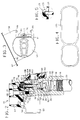
- Fig. 1 is a cross-sectional view of the combined gas control valve and thermally responsive gas shutoff valve constructed in accordance with the present invention;
- Fig. 2 is a partial cross-sectional view of the valve of Fig. 1, showing the shutoff valve components in positions initially existing when the shutoff valve is connected to the control valve;
- Fig. 3 is a top plan view of the shutoff valve of Fig. 2;
- Fig. 4 is a plan view of a gasket used in the construction of the control valve of Fig. 1; and
- Fig. 5 is an enlarged cross-sectional view of a sealed joint, formed from the gasket of Fig. 4, between two body portions of the control valve of Fig. 1.
-
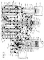
- Referring to Fig. 1, the gas valve of this invention comprises the combination of an electrically operated control valve indicated generally at 12 and a thermally responsive shutoff valve indicated generally at 14.
Control valve 12 and shutoff valve 14 are detachably connected to each other by means to be hereinafter described. In the illustrated embodiment, combinedvalves 12 and 14 are utilized to control the flow of gas from a gas source (not shown) to a burner, shown partially at 15, in a gas-fired clothes dryer. - Shutoff valve 14 is provided with a
metallic body 16, preferably an aluminum casting. Pipe threads are provided at aninlet opening 18 to receive a threadedconduit 20 leading from the gas source. Extending between inlet opening 18 and anoutlet opening 22 aregas passageways - A
lower portion 32 of a metallic valve stem 34 is provided with a rubber O-ring 36 which cooperates withpassageway 28 so as to control the flow of gas, in an on and off manner, between inlet opening 18 andoutlet opening 22.Passageway 28 and part of thelower portion 32 of valve stem 34 are similarly tapered so as to provide an adequate metal-to-metal gas seal in the event O-ring 36 should be damaged or destroyed. For example, O-ring 36 could be damaged or destroyed due to exposure to an abnormally high temperature and/or flame which could exist, for example, due to a fire in the dwelling in which the clothes dryer utilizing shutoff valve 14 is located. - An
upper portion 38 of valve stem 34 is slidably received in a metallic tube 40. Secured in an upper closed end of tube 40 by adisc 42 and aspring 44 is asmall mass 46 of a eutectic material.Disc 42 is hexagonally shaped on its outer periphery so as to enable themass 46 of eutectic material, when it is melted, to flow downwardly between the periphery ofdisc 42 and the inside wall surface of tube 40. - A
spring 48 is nested at one end on ashoulder 50 betweenpassageways boss 52 ofvalve stem 34.Spring 48 is effective to provide a closing bias tovalve stem 34. An O-ring 54 surrounds tube 40 in a snug fit and is compressed in arecess 56 extending downwardly from atop surface 58 ofvalve body 16 so as to prevent gas from escaping from outlet opening 22 past tube 40. O-ring 54 is secured therein by awasher 60 which is staked tovalve body 16 at 62. - A
knob 64, made of polymeric material, is attached by astud 66 tovalve body 16.Stud 66 includes a steppedupper portion 68 cooperative with a steppedopening 70 inknob 64 so as to enable rotation ofknob 64 aroundstud 66 whenstud 66 is secured tovalve body 16.Stud 66 includes alower knurled portion 72 which is secured in anopening 74 ofvalve body 16.Knob 64 is provided with acam surface 76 which cooperates with the upper closed end of tube 40 so as to adjust the position ofvalve stem 34. As shown in Fig. 3, the periphery ofknob 64 is circular except for a smallstraight portion 78. - Referring to Fig.. 3,
valve body 16 includes anintegral flange 80 adapted to be secured by any convenient means (not shown) to asurface 82 of the clothes dryer chassis.Valve body 16 further includes a taperedsurface 84 surrounding itsoutlet opening 22, and a pair oftabs 86 extending outwardly from taperedsurface 84 and toward each other. -
Control valve 12 comprises a plurality of parts made of the same polymeric material, preferably a polyphenylene sulfide (PPS) compound. Specifically,control valve 12 includes a valve body comprised of amiddle body portion 88, anupper body portion 90 and a lower body portion 92, all made of the same PPS compound.Control valve 12 further includes acoil cover 94 and regulator covers 96 and 98 also made of the same PPS compound. -
Middle body portion 88 is provided with aninlet opening 100 which is aligned with outlet opening 22 ofvalve body 16.Body portion 88 includes atapered surface 102 surrounding itsinlet opening 100, whichtapered surface 102 is positioned tightly against taperedsurface 84 ofvalve body 16 bytabs 86, shown in Fig. 3, when shutoff valve 14 andcontrol valve 12 are connected together. An O-ring 104 is adapted to be compressed in arecess 106 extending inwardly from taperedsurface 102 ofbody portion 88 so as to prevent gas from escaping to atmosphere at the connection of taperedsurfaces -
Middle body portion 88 is provided with anoutlet opening 108. Ametallic sleeve 110 is insert-molded intooutlet opening 108.Sleeve 110 has anopening 112 therethrough. Anorifice screw 114 is threadedly engaged tosleeve 110 at one end ofopening 112. The outer surface ofsleeve 110 is provided with a plurality ofgrooves 116. The grooved surface provides a convenient means for attachingburner 15 and provides a means for dissipating heat in the event that burner flame should exist at or near theorifice screw 114. For example, a low gas pressure condition could cause the burner flame to "burn back" atorifice screw 114. Such heat dissipation preventsbody portion 88 from reaching a temperature at which it would become structurally unstable. -
Middle body portion 88 is joined toupper body portion 90 to definechambers chamber 124.Middle body portion 88 is provided with an upwardly extendingledge 126 which extends in a continuous loop aroundchambers Ledge 126 is received in agroove 128 ofupper body portion 90. - During assembly of
control valve 12, agasket 130, shown in Fig. 4, is positioned ingroove 128.Gasket 130 is made of a metal-filled PPS compound. When sufficient heat is applied to the immediate vicinity ofledge 126,groove 128 andgasket 130,gasket 130 melts, forming an adhesive 131, shown more clearly in Fig. 5, which provides a gas-tight seal and a structurally strong joint betweenbody portions -
Middle body portion 88 is provided with a downwardly extending ledge 134 which extends in a continuous loop aroundchamber 124. Ledge 134 is received in agroove 136 of lower body portion 92. A gasket, made of a metal-filled PPS compound, is positioned ingroove 136. When sufficient heat is applied to the vicinity of ledge 134,groove 136 and the gasket, the gasket melts, forming an adhesive 138 which provides a gas-tight seal and a structurally strong joint betweenbody portions 88 and 92. -
Control valve 12 includes two solenoid valves indicated generally at 140 and 142, and a pressure regulator indicated generally at 144. -
Solenoid valve 140 includes ametallic plunger 146 slidably received in aguide sleeve 148. The lower end ofguide sleeve 148 is insert-molded in a downwardly extendingboss 150 ofupper body portion 90. The upper end ofguide sleeve 148 is closed and is slightly reduced in diameter from the remainder ofguide sleeve 148 and receives, in a press fit, ametallic core member 152. The lower portion ofcore member 152 is provided with aconical extension 154. The upper portion ofplunger 146 is provided with aconical recess 156 which cooperates withconical extension 154. - Attached to the lower end of
plunger 146 is aresilient valve member 158.Valve member 158 cooperates with avalve seat 160 surrounding anopening 161 inmiddle body portion 88 and is biased to its closed position by aspring 162.Spring 162 is positioned between an upper portion ofplunger 146 and a lower portion ofcore member 152. - Surrounding
guide sleeve 148 is abobbin 164 on which is wound awire coil 166 of an appropriate gauge and number of turns of wire. The start and finish ends (not shown) ofcoil 166 are connected to appropriate circuitry (not shown) for controlling energizing ofcoil 166. - A magnetic flux path is provided by a
metallic bracket 168 which has anopening 170 in atop leg 172 thereof and anopening 174 in a bottom leg 176 thereof.Guide sleeve 148 extends throughopenings -
Solenoid valve 142 is the same in construction assolenoid valve 140.Solenoid valve 142 includes aplunger 178 and aguide sleeve 180. The lower end ofguide sleeve 180 is insert-molded in a downwardly extendingboss 182 ofupper body portion 90.Solenoid valve 142 also includes acore member 184 having aconical extension 186 which cooperates with aconical recess 188 ofplunger 178, avalve member 190 which cooperates with avalve seat 192 surrounding anopening 193 inmiddle portion 88, and abiasing spring 194. -
Solenoid valve 142 also includes abobbin 196 and awire coil 198.Solenoid valve 142 further includes abracket 200 having anopening 202 in atop leg 204 thereof and anopening 206 in abottom leg 208 thereof.Guide sleeve 180 extends throughopenings -
Pressure regulator 144 includes apoppet valve 210 cooperative with a valve seat 212 surrounding anopening 214 inmiddle body portion 88. An upper portion ofvalve 210 is provided with a plurality offins 216 which alignvalve 210 inopening 214. Thefins 216 are spaced from each other around the periphery ofvalve 210 so as to provide passageways therebetween for gas to flow through opening 214 fromchamber 124 tochamber 122. The upper portion ofvalve 210 is also provided with a taperedportion 218. The taperedportion 218 is effective to reduce the flow of gas throughopening 214 whenvalve 210 moves downwardly and to increase the flow of gas throughopening 214 whenvalve 210 moves upwardly. - A flexible diaphragm 220 is clamped at its outer periphery between lower body portion 92 and
regulator cover 96, and is nested at its inner periphery in agroove 222 in a lower portion ofvalve 210. Anotherflexible diaphragm 224 is clamped at its outer periphery between regulator covers 96 and 98. - A gasket, made of a metal-filled PPS compound, is positioned in a
continuous groove 228 of regulator cover 96 during assembly. Sufficient heat is then applied so as to cause the gasket to melt and thereby form an adhesive 229 which provides a gas-tight seal and a structurally strong joint between lower body portion 92 andregulator cover 96. In a similar fashion, a metal-filled PPS compound gasket is positioned in acontinuous groove 232 ofregulator cover 96 and when melted, forms an adhesive 233 which provides a gas-tight seal and a structurally strong joint between regulator covers 96 and 98. It is noted that the feature of a gas-tight seal provided byadhesives diaphragms 220 and 224. -
Poppet valve 210 is biased downwardly againstdiaphragm 224 by aspring 234 which rests at one end against aninternal ledge 236 invalve 210 and at its other end against an adjusting screw 238. An O-ring 240 in a groove 242 of screw 238 provides a desired gas-tight seal betweenchamber 122 and atmosphere.Diaphragm 224 is biased upwardly againstvalve 210 by aspring 244.Spring 244 rests at one end against aplate 246 on the underside ofdiaphragm 224 and at its other end inside acavity 248 of ascrew 250.Screw 250 is provided with threads on both ends 252 and 254 so that it can be reversed. Whenscrew 250 is reversed,spring 244 rests inside acavity 256, thereby changing the biasing force exerted ondiaphragm 224 byspring 244. In practice,screw 250 is used in one position when the gas being controlled is LP (liquid propane) and in the other position when the gas being controlled is natural gas. -
Regulator cover 98,screw 250 and one side ofdiaphragm 224 define achamber 258.Chamber 258 is at atmospheric pressure due to its being exposed to atmosphere through anopening 260 inscrew 250.Regulator cover 96,valve 210, one side of diaphragm 220 and the other side ofdiaphragm 224 define achamber 262.Valve 210 is provided with spacedopenings 264 at its lower end.Chamber 262 is at the pressure existing inchamber 122 due tochamber 262 being connected tochamber 122 throughopenings 264 and the interior ofvalve 210. -
Upper body portion 90 is also provided with a pressure tap fitting including a threadedrecess 265 and anopening 266 betweenrecess 265 andchamber 122. When pressure is not being checked, opening 266 is closed by ascrew 268 secured inrecess 265. -
Coil cover 94 is provided with atop portion 269 which overliessolenoid valves top portion 269 is aperipheral lip 270 which overlies atop edge 272 ofupper body portion 90.Coil cover 94 is secured toupper body portion 90 by ascrew 274 which is captivated in anopening 276 incoil cover 94 and extends into a threaded opening 278 inupper body portion 90. - When it is desired to connect
control valve 12 to shutoff valve 14 or disconnect them from each other,knob 64 is rotated to an angular position wherein no part ofknob 64 overliesmiddle body portion 88, such a knob position being shown in Figs. 2 and 3.Middle body portion 88 ofcontrol valve 12 is provided with recess means (not shown) which cooperate withtabs 86 to effect sliding contact between taperedsurface 84 ofvalve body 16 and taperedsurface 102 ofmiddle body portion 88 as such connection or disconnection is being made. - When
control valve 12 and shutoff valve 14 are properly connected to each other,knob 64 can be rotated to an OFF position or to an ON position. The OFF position is attained whenknob 64 is rotated 90 degrees clockwise from the position illustrated in FIGS. 2 and 3; the ON position is attained whenknob 64 is rotated 180° clockwise. - As
knob 64 is rotated clockwise from the position illustrated in Figs. 2 and 3,cam surface 76 pushes downwardly on tube 40. Tube 40 is moved downwardly, compressingspring 44. In the OFF position, tube 40 has been moved downwardly, but not enough to causedisc 42 in tube 40 to be in contact with valve stem 34 so that valve stem 34 is in the same position as illustrated in Fig. 2 wherein gas flow through shutoff valve 14 is blocked. - In the ON position, such position being illustrated in Fig. 1,
cam surface 76 has pushed sufficiently downwardly on tube 40 to causedisc 42 therein to contactvalve stem 34 and force valve stem 34 downwardly so as to enable gas to flow throughpassageway 28. That is to say, gas can then flow from inlet opening 18 throughpassageways outlet opening 22. Withknob 64 in the ON position, gas flow from outlet opening 22 is controlled bycontrol valve 12. - In the preferred embodiment,
control valve 12 is operated in a manner such thatsolenoid valve 140 is energized beforesolenoid valve 142. However, it is to be understood that in other embodiments,solenoid valve 140 could be energized aftersolenoid valve 142 or at the same time assolenoid valve 142. - When
solenoid valve 140 is energized, gas can then flow from outlet opening 22 of shutoff valve 14 through inlet opening 100 ofcontrol valve 12, throughchamber 120, opening 161,chamber 124, opening 214, and intochamber 122. Whensolenoid valve 142 is subsequently energized, gas can then flow fromchamber 122 throughopenings orifice screw 114 toburner 15. - As previously described, the polymeric material used in
control valve 12 is a PPS compound. The various parts made of the PPS compound are stable so long as the temperature to which they are exposed remains below a certain temperature which, in the PPS compound, is approximately 260°C (500°F). Under normal operating conditions, the temperature to whichcontrol valve 12 is exposed is well below 260°C (500°F). - In the
event control valve 12 is exposed to a temperature above approximately 260°C (500°F). For example, due to a fire in a dwelling, shutoff valve 14 is also exposed. At a temperature above a value at which shutoff valve 14 would normally operate, but well below 260°C (500°F), for example, at approximately 93°C (200°F), themass 46 of eutectic material in shutoff valve 14 will melt, enabling valve stem 34 to be moved upwardly byspring 48 andclose gas passageway 28. Thus, should controlvalve 12 be exposed to 260°C (500°F) and subsequently become unstable, gas would not leak fromcontrol valve 12 because shutoff valve 14 would already have terminated the flow of gas to controlvalve 12. - It is to be noted that with the PPS compound and the 93°C (200°F) eutectic material, there is a temperature margin of approximately 150°C (300°F) between the temperature at which shutoff valve 14 closes and the temperature at which the polymeric material parts become unstable. It is to be understood that other polymeric materials and other eutectic materials could be utilized so long as, in addition to satisfying all other requirements, they provide an adequate temperature margin between the temperature at which safety valve 14 closes and the temperature at which the polymeric material parts become unstable.
- In addition to providing the described high-temperature protection to control
valve 12, shutoff valve 14 also provides protection to controlvalve 12 against a high level of mechanical stress. Specifically,valve body 16 of shutoff valve 14 is provided with a pipe-threaded inlet opening 18 which receives the pipe-threadedconduit 20. Sincevalve body 16 is made of metal, it can easily withstand the typical mechanical forces exerted thereon as a result of so connectingconduit 20. If such a pipe-thread connection were required to be made directly to controlvalve 12, that is, to a part made of a PPS compound such asmiddle body portion 88 except with a pipe-threaded inlet opening, it is believed that the typical mechanical forces that would be exerted on such a part would damage the part. - It is to be noted that there are polymeric materials available which would enable a valve body molded therefrom to possess sufficient mechanical strength and high temperature stability so as to enable elimination of a shutoff valve. However, the cost of such a polymeric material is such that the use of a valve body made of less expensive polymeric material combined with a shutoff valve, as in the present invention, is believed to be a considerably less expensive arrangement.
- While a preferred embodiment of the present invention has been illustrated and described in detail in the drawings and foregoing description, it will be recognized that many changes and modifications will occur to those skilled in the art.
Claims (3)
- A gas valve havinga control valve (12) including a valve body (88, 90, 92, 94, 96, 98), and having a gas inlet (100) and electrically operated valve means (140, 142) for controlling flow of gas through said control valve (12); anda shutoff valve (14) having a metal valve body (16) and being detachably connected to said control valve (12) upstream therefrom, with a gas outlet (22) of said shutoff valve (14) being in communication with said control valve inlet (100), and said shutoff valve (14) including thermally responsive valve means effective for terminating flow of gas to said control valve (12) in response to exposure to an abnormal temperature value,
characterized in that the valve body (88, 90, 92, 94, 96, 98) of said control valve (12) is made of polymeric material which becomes structurally unstable at temperatures above approximately 260°C, and said thermally responsive valve means (12) of said shutoff valve (14) is effective for terminating flow of gas to said control valve (12) in response to exposure to a temperature value considerably lower than a temperature value at which, if exposed thereto, said polymeric control valve body (88, 90, 92, 94, 96, 98) would become structurally unstable, the shutoff valve body (16) has a tapered surface (84) surrounding its outlet opening (22) and a pair of tabs (86) extending outwardly from the tapered surface (84) and towards each other, and the control valve body (88) includes a tapered surface (102) surrounding said gas inlet (100) and positioned tightly against the tapered surface of the shut-off valve body (16) by the tabs (86), said tabs (86) being received in recess means of the control valve body (88) to effect sliding contact between the tapered surfaces (84, 102) for connection and disconnection of the valve bodies (16, 88). - The gas valve according to claim 1, characterized in that said polymeric material comprises a polyphenylene sulfide (PPS) compound.
- The gas valve according to claim 2, characterized in that said control valve body comprises a plurality of body portions (88, 90, 92, 94, 96, 98) made of said PPS compound and connected together by an adhesive formed from a metal-filled PPS compound.
Applications Claiming Priority (2)
| Application Number | Priority Date | Filing Date | Title |
|---|---|---|---|
| US08/186,167 US5379794A (en) | 1994-01-25 | 1994-01-25 | Gas control valve having polymeric material body combined with thermally responsive gas shutoff valve having metallic body |
| US186167 | 1994-01-25 |
Publications (3)
| Publication Number | Publication Date |
|---|---|
| EP0664421A1 EP0664421A1 (en) | 1995-07-26 |
| EP0664421B1 EP0664421B1 (en) | 1997-09-10 |
| EP0664421B2 true EP0664421B2 (en) | 2000-10-25 |
Family
ID=22683900
Family Applications (1)
| Application Number | Title | Priority Date | Filing Date |
|---|---|---|---|
| EP19940630072 Expired - Lifetime EP0664421B2 (en) | 1994-01-25 | 1994-12-15 | Gas control valve |
Country Status (8)
| Country | Link |
|---|---|
| US (1) | US5379794A (en) |
| EP (1) | EP0664421B2 (en) |
| KR (1) | KR950023882A (en) |
| AU (1) | AU680701B2 (en) |
| CA (1) | CA2130969C (en) |
| DE (1) | DE69405532T3 (en) |
| DK (1) | DK0664421T4 (en) |
| NZ (1) | NZ270076A (en) |
Families Citing this family (42)
| Publication number | Priority date | Publication date | Assignee | Title |
|---|---|---|---|---|
| US5887847A (en) * | 1997-09-18 | 1999-03-30 | Automatic Switch Company | Digitally controllable flow rate valve |
| IT1297323B1 (en) * | 1997-10-20 | 1999-09-01 | Emer Srl | CONTROL EQUIPMENT FOR GAS DELIVERY IN GAS SYSTEMS FOR AUTOTRACTION |
| US6374781B1 (en) * | 1998-09-02 | 2002-04-23 | Sanshin Kogyo Kabushiki Kaisha | Oil injection lubrication system for two-cycle engines |
| US6199573B1 (en) | 1998-09-09 | 2001-03-13 | Craft-Weld Enterprises, Inc. | Gas flow arrestor |
| US6161572A (en) * | 1998-12-18 | 2000-12-19 | Lancer Partnership, Ltd. | Premix dispensing valve with integral pressure regulation |
| US6938634B2 (en) * | 2003-05-30 | 2005-09-06 | Robertshaw Controls Company | Fuel control mechanism and associated method of use |
| US6941962B2 (en) * | 2003-05-30 | 2005-09-13 | Robertshaw Controls Company | Convertible control device capable of regulating fluid pressure for multiple fluid types and associated method of use |
| DE102004028039B3 (en) * | 2004-06-09 | 2005-04-14 | Mertik Maxitrol Gmbh & Co. Kg | Fixed connector to link e.g. a gas cooking oven with a gas supply pipe has a plunger operating in conjunction with a valve |
| US7643753B2 (en) * | 2005-09-29 | 2010-01-05 | Broadlight Ltd. | Enhanced passive optical network (PON) processor |
| US7677236B2 (en) | 2006-05-17 | 2010-03-16 | David Deng | Heater configured to operate with a first or second fuel |
| US7434447B2 (en) * | 2006-05-17 | 2008-10-14 | David Deng | Oxygen depletion sensor |
| US7607426B2 (en) | 2006-05-17 | 2009-10-27 | David Deng | Dual fuel heater |
| US8011920B2 (en) | 2006-12-22 | 2011-09-06 | David Deng | Valve assemblies for heating devices |
| US8152515B2 (en) * | 2007-03-15 | 2012-04-10 | Continental Appliances Inc | Fuel selectable heating devices |
| US8241034B2 (en) | 2007-03-14 | 2012-08-14 | Continental Appliances Inc. | Fuel selection valve assemblies |
| US20080029170A1 (en) * | 2006-08-02 | 2008-02-07 | O'reilly Edward | Three-in-one valve and control system |
| US8545216B2 (en) * | 2006-12-22 | 2013-10-01 | Continental Appliances, Inc. | Valve assemblies for heating devices |
| US7654820B2 (en) * | 2006-12-22 | 2010-02-02 | David Deng | Control valves for heaters and fireplace devices |
| US8517718B2 (en) | 2009-06-29 | 2013-08-27 | David Deng | Dual fuel heating source |
| US8506290B2 (en) * | 2009-06-29 | 2013-08-13 | David Deng | Heating apparatus with air shutter adjustment |
| US9829195B2 (en) * | 2009-12-14 | 2017-11-28 | David Deng | Dual fuel heating source with nozzle |
| US8752541B2 (en) | 2010-06-07 | 2014-06-17 | David Deng | Heating system |
| US10073071B2 (en) | 2010-06-07 | 2018-09-11 | David Deng | Heating system |
| CN202328495U (en) | 2011-11-16 | 2012-07-11 | 普鲁卡姆电器(上海)有限公司 | Multi-air-source balanced gas-fired heater with 360-degree ventilation door adjusting device |
| US9222670B2 (en) | 2010-12-09 | 2015-12-29 | David Deng | Heating system with pressure regulator |
| US8985094B2 (en) | 2011-04-08 | 2015-03-24 | David Deng | Heating system |
| US9200802B2 (en) | 2011-04-08 | 2015-12-01 | David Deng | Dual fuel heater with selector valve |
| US9739389B2 (en) | 2011-04-08 | 2017-08-22 | David Deng | Heating system |
| US10222057B2 (en) | 2011-04-08 | 2019-03-05 | David Deng | Dual fuel heater with selector valve |
| CN102506198B (en) * | 2011-10-20 | 2013-05-22 | 南京普鲁卡姆电器有限公司 | Dual-gas-source gas self-adaptive main control valve |
| US9022064B2 (en) | 2012-05-10 | 2015-05-05 | David Deng | Dual fuel control device with auxiliary backline pressure regulator |
| US9091431B2 (en) | 2012-09-13 | 2015-07-28 | David Deng | Dual fuel valve with air shutter adjustment |
| US9423123B2 (en) | 2013-03-02 | 2016-08-23 | David Deng | Safety pressure switch |
| US9752779B2 (en) | 2013-03-02 | 2017-09-05 | David Deng | Heating assembly |
| US10240789B2 (en) | 2014-05-16 | 2019-03-26 | David Deng | Dual fuel heating assembly with reset switch |
| US10429074B2 (en) | 2014-05-16 | 2019-10-01 | David Deng | Dual fuel heating assembly with selector switch |
| US10993546B2 (en) * | 2016-10-28 | 2021-05-04 | Sleep Number Corporation | Noise reducing plunger |
| CN111742174A (en) * | 2017-10-13 | 2020-10-02 | 苏波尔产品设计公司 | Gas leak detection and shut down system |
| US10877498B2 (en) | 2017-10-27 | 2020-12-29 | Brasscraft Manufacturing Company | Excess flow and thermal valve |
| KR20200112833A (en) * | 2017-12-11 | 2020-10-05 | 엣세이띠 엣세.삐.아. | Valve delivery device |
| US10598298B2 (en) * | 2018-08-27 | 2020-03-24 | Borg Warner Inc. | Control valve and hydraulic control module including the same |
| US11832728B2 (en) | 2021-08-24 | 2023-12-05 | Sleep Number Corporation | Controlling vibration transmission within inflation assemblies |
Family Cites Families (9)
| Publication number | Priority date | Publication date | Assignee | Title |
|---|---|---|---|---|
| US4348006A (en) * | 1979-07-19 | 1982-09-07 | Kerotest Manufacturing Corp. | Plastic valve assembly |
| JPS57208376A (en) * | 1981-06-16 | 1982-12-21 | Matsushita Electric Ind Co Ltd | Safety device of combustion equipment |
| US4424830A (en) * | 1981-12-16 | 1984-01-10 | Emerson Electric Co. | Gas valve |
| US4502661A (en) * | 1983-11-04 | 1985-03-05 | Eaton Corporation | Electrically actuated valve assembly |
| US4695602A (en) * | 1985-02-28 | 1987-09-22 | Lnp Corporation | Fiber reinforced thermoplastics containing silicone interpenetrating polymer networks |
| US4844112A (en) * | 1988-09-30 | 1989-07-04 | Eaton Corporation | Electrically operated valve assembly |
| US5020563A (en) * | 1990-06-22 | 1991-06-04 | Gas Research Institute | Connector set |
| AT401569B (en) * | 1991-12-12 | 1996-10-25 | Vaillant Gmbh | HEATING DEVICE |
| JPH081944B2 (en) * | 1993-05-31 | 1996-01-10 | 株式会社日立製作所 | Semiconductor device |
-
1994
- 1994-01-25 US US08/186,167 patent/US5379794A/en not_active Expired - Lifetime
- 1994-08-26 CA CA 2130969 patent/CA2130969C/en not_active Expired - Lifetime
- 1994-12-06 NZ NZ270076A patent/NZ270076A/en not_active IP Right Cessation
- 1994-12-10 KR KR1019940033582A patent/KR950023882A/en active IP Right Grant
- 1994-12-12 AU AU80383/94A patent/AU680701B2/en not_active Ceased
- 1994-12-15 DK DK94630072T patent/DK0664421T4/en active
- 1994-12-15 DE DE1994605532 patent/DE69405532T3/en not_active Expired - Lifetime
- 1994-12-15 EP EP19940630072 patent/EP0664421B2/en not_active Expired - Lifetime
Non-Patent Citations (2)
| Title |
|---|
| Brochure titled " Ein kleines Ventil für die Sicherheit der Gasgeräte" from the company Streif Brandschutz AG, Chur(CH) † |
| Brochure titled " Gaskombinationsventile für automatische Zündsysteme" from the company Honeywell, four pages with the imprint Form N.D3H-78, Honeywell 1981, EN3R-0580.3/81 † |
Also Published As
| Publication number | Publication date |
|---|---|
| EP0664421B1 (en) | 1997-09-10 |
| DK0664421T4 (en) | 2001-02-26 |
| KR950023882A (en) | 1995-08-18 |
| EP0664421A1 (en) | 1995-07-26 |
| DE69405532T3 (en) | 2001-05-31 |
| DK0664421T3 (en) | 1998-04-27 |
| DE69405532D1 (en) | 1997-10-16 |
| CA2130969C (en) | 1997-12-02 |
| AU8038394A (en) | 1995-08-03 |
| US5379794A (en) | 1995-01-10 |
| NZ270076A (en) | 1995-09-26 |
| DE69405532T2 (en) | 1998-04-09 |
| CA2130969A1 (en) | 1995-07-26 |
| AU680701B2 (en) | 1997-08-07 |
Similar Documents
| Publication | Publication Date | Title |
|---|---|---|
| EP0664421B2 (en) | Gas control valve | |
| US6062245A (en) | Gaseous fuel burner manifold with integral pressure regulator assembly | |
| US7081223B2 (en) | Method for manufacturing a rotatable plug element and valve | |
| US5988204A (en) | Adjustable fluid flow regulator | |
| US5988215A (en) | Fluid control assembly | |
| US3777777A (en) | Flow control device | |
| US3978880A (en) | Regulator valve diaphragm and valve assembly including the same | |
| US5092519A (en) | Control system for water heaters | |
| US3915378A (en) | Manifold valve for domestic gas ovens | |
| US4289476A (en) | Direct ignition gas burner control system | |
| US4179097A (en) | Safety shut-off valve | |
| US2627911A (en) | Fuel control device | |
| US5632466A (en) | Piston actuated pressure reducing valve | |
| US1971801A (en) | Oven heat control | |
| US4286768A (en) | Stepped pressure gas valve apparatus | |
| US3858611A (en) | Step opening thermostatic control device | |
| US3433255A (en) | Valve assembly | |
| US3556117A (en) | Unitary pressure regulator and flow control device | |
| US3704854A (en) | Flow control device with pressure regulation | |
| JPS5832059Y2 (en) | gas proportional control valve | |
| AU741984B2 (en) | Fluid control assembly | |
| EP1209408B1 (en) | Valve device for bottles of liquefied gas | |
| CA1123706A (en) | Safety shut-off valve | |
| JPH0249479Y2 (en) | ||
| KR870000103Y1 (en) | Opening and closing device of gas safety valve |
Legal Events
| Date | Code | Title | Description |
|---|---|---|---|
| PUAI | Public reference made under article 153(3) epc to a published international application that has entered the european phase |
Free format text: ORIGINAL CODE: 0009012 |
|
| AK | Designated contracting states |
Kind code of ref document: A1 Designated state(s): DE DK FR GB IT NL |
|
| 17P | Request for examination filed |
Effective date: 19950720 |
|
| 17Q | First examination report despatched |
Effective date: 19960712 |
|
| GRAG | Despatch of communication of intention to grant |
Free format text: ORIGINAL CODE: EPIDOS AGRA |
|
| GRAH | Despatch of communication of intention to grant a patent |
Free format text: ORIGINAL CODE: EPIDOS IGRA |
|
| GRAH | Despatch of communication of intention to grant a patent |
Free format text: ORIGINAL CODE: EPIDOS IGRA |
|
| GRAH | Despatch of communication of intention to grant a patent |
Free format text: ORIGINAL CODE: EPIDOS IGRA |
|
| GRAA | (expected) grant |
Free format text: ORIGINAL CODE: 0009210 |
|
| AK | Designated contracting states |
Kind code of ref document: B1 Designated state(s): DE DK FR GB IT NL |
|
| REF | Corresponds to: |
Ref document number: 69405532 Country of ref document: DE Date of ref document: 19971016 |
|
| ITF | It: translation for a ep patent filed |
Owner name: UFFICIO BREVETTI RICCARDI & C. |
|
| ET | Fr: translation filed | ||
| REG | Reference to a national code |
Ref country code: DK Ref legal event code: T3 |
|
| PLBI | Opposition filed |
Free format text: ORIGINAL CODE: 0009260 |
|
| PLBF | Reply of patent proprietor to notice(s) of opposition |
Free format text: ORIGINAL CODE: EPIDOS OBSO |
|
| 26 | Opposition filed |
Opponent name: HONEYWELL AG Effective date: 19980610 |
|
| NLR1 | Nl: opposition has been filed with the epo |
Opponent name: HONEYWELL AG |
|
| PLBF | Reply of patent proprietor to notice(s) of opposition |
Free format text: ORIGINAL CODE: EPIDOS OBSO |
|
| PLBF | Reply of patent proprietor to notice(s) of opposition |
Free format text: ORIGINAL CODE: EPIDOS OBSO |
|
| PLAW | Interlocutory decision in opposition |
Free format text: ORIGINAL CODE: EPIDOS IDOP |
|
| PLAW | Interlocutory decision in opposition |
Free format text: ORIGINAL CODE: EPIDOS IDOP |
|
| PUAH | Patent maintained in amended form |
Free format text: ORIGINAL CODE: 0009272 |
|
| STAA | Information on the status of an ep patent application or granted ep patent |
Free format text: STATUS: PATENT MAINTAINED AS AMENDED |
|
| 27A | Patent maintained in amended form |
Effective date: 20001025 |
|
| AK | Designated contracting states |
Kind code of ref document: B2 Designated state(s): DE DK FR GB IT NL |
|
| ITF | It: translation for a ep patent filed |
Owner name: RICCARDI SERGIO |
|
| NLR2 | Nl: decision of opposition | ||
| NLR3 | Nl: receipt of modified translations in the netherlands language after an opposition procedure | ||
| ET3 | Fr: translation filed ** decision concerning opposition | ||
| REG | Reference to a national code |
Ref country code: DK Ref legal event code: T4 |
|
| REG | Reference to a national code |
Ref country code: GB Ref legal event code: IF02 |
|
| PGFP | Annual fee paid to national office [announced via postgrant information from national office to epo] |
Ref country code: DK Payment date: 20081230 Year of fee payment: 15 |
|
| PGFP | Annual fee paid to national office [announced via postgrant information from national office to epo] |
Ref country code: GB Payment date: 20081229 Year of fee payment: 15 |
|
| REG | Reference to a national code |
Ref country code: DK Ref legal event code: EBP |
|
| GBPC | Gb: european patent ceased through non-payment of renewal fee |
Effective date: 20091215 |
|
| PG25 | Lapsed in a contracting state [announced via postgrant information from national office to epo] |
Ref country code: GB Free format text: LAPSE BECAUSE OF NON-PAYMENT OF DUE FEES Effective date: 20091215 |
|
| PG25 | Lapsed in a contracting state [announced via postgrant information from national office to epo] |
Ref country code: DK Free format text: LAPSE BECAUSE OF NON-PAYMENT OF DUE FEES Effective date: 20100104 |
|
| PGFP | Annual fee paid to national office [announced via postgrant information from national office to epo] |
Ref country code: FR Payment date: 20110107 Year of fee payment: 17 |
|
| PGFP | Annual fee paid to national office [announced via postgrant information from national office to epo] |
Ref country code: NL Payment date: 20101224 Year of fee payment: 17 Ref country code: IT Payment date: 20101228 Year of fee payment: 17 |
|
| PGFP | Annual fee paid to national office [announced via postgrant information from national office to epo] |
Ref country code: DE Payment date: 20101229 Year of fee payment: 17 |
|
| REG | Reference to a national code |
Ref country code: NL Ref legal event code: V1 Effective date: 20120701 |
|
| REG | Reference to a national code |
Ref country code: FR Ref legal event code: ST Effective date: 20120831 |
|
| REG | Reference to a national code |
Ref country code: DE Ref legal event code: R119 Ref document number: 69405532 Country of ref document: DE Effective date: 20120703 |
|
| PG25 | Lapsed in a contracting state [announced via postgrant information from national office to epo] |
Ref country code: DE Free format text: LAPSE BECAUSE OF NON-PAYMENT OF DUE FEES Effective date: 20120703 |
|
| PG25 | Lapsed in a contracting state [announced via postgrant information from national office to epo] |
Ref country code: IT Free format text: LAPSE BECAUSE OF NON-PAYMENT OF DUE FEES Effective date: 20111215 |
|
| PG25 | Lapsed in a contracting state [announced via postgrant information from national office to epo] |
Ref country code: NL Free format text: LAPSE BECAUSE OF NON-PAYMENT OF DUE FEES Effective date: 20120701 |
|
| PG25 | Lapsed in a contracting state [announced via postgrant information from national office to epo] |
Ref country code: FR Free format text: LAPSE BECAUSE OF NON-PAYMENT OF DUE FEES Effective date: 20120102 |