EP0664412B1 - Vorrichtung zum Bremsen einer rotierenden Welle gegenüber einem ruhenden Maschinenteil - Google Patents
Vorrichtung zum Bremsen einer rotierenden Welle gegenüber einem ruhenden Maschinenteil Download PDFInfo
- Publication number
- EP0664412B1 EP0664412B1 EP95100471A EP95100471A EP0664412B1 EP 0664412 B1 EP0664412 B1 EP 0664412B1 EP 95100471 A EP95100471 A EP 95100471A EP 95100471 A EP95100471 A EP 95100471A EP 0664412 B1 EP0664412 B1 EP 0664412B1
- Authority
- EP
- European Patent Office
- Prior art keywords
- housing part
- disc
- radial
- packages
- annular
- Prior art date
- Legal status (The legal status is an assumption and is not a legal conclusion. Google has not performed a legal analysis and makes no representation as to the accuracy of the status listed.)
- Expired - Lifetime
Links
Images



Classifications
-
- F—MECHANICAL ENGINEERING; LIGHTING; HEATING; WEAPONS; BLASTING
- F16—ENGINEERING ELEMENTS AND UNITS; GENERAL MEASURES FOR PRODUCING AND MAINTAINING EFFECTIVE FUNCTIONING OF MACHINES OR INSTALLATIONS; THERMAL INSULATION IN GENERAL
- F16D—COUPLINGS FOR TRANSMITTING ROTATION; CLUTCHES; BRAKES
- F16D55/00—Brakes with substantially-radial braking surfaces pressed together in axial direction, e.g. disc brakes
- F16D55/24—Brakes with substantially-radial braking surfaces pressed together in axial direction, e.g. disc brakes with a plurality of axially-movable discs, lamellae, or pads, pressed from one side towards an axially-located member
- F16D55/26—Brakes with substantially-radial braking surfaces pressed together in axial direction, e.g. disc brakes with a plurality of axially-movable discs, lamellae, or pads, pressed from one side towards an axially-located member without self-tightening action
- F16D55/36—Brakes with a plurality of rotating discs all lying side by side
- F16D55/40—Brakes with a plurality of rotating discs all lying side by side actuated by a fluid-pressure device arranged in or one the brake
-
- F—MECHANICAL ENGINEERING; LIGHTING; HEATING; WEAPONS; BLASTING
- F16—ENGINEERING ELEMENTS AND UNITS; GENERAL MEASURES FOR PRODUCING AND MAINTAINING EFFECTIVE FUNCTIONING OF MACHINES OR INSTALLATIONS; THERMAL INSULATION IN GENERAL
- F16D—COUPLINGS FOR TRANSMITTING ROTATION; CLUTCHES; BRAKES
- F16D65/00—Parts or details
- F16D65/78—Features relating to cooling
- F16D65/84—Features relating to cooling for disc brakes
- F16D65/853—Features relating to cooling for disc brakes with closed cooling system
-
- F—MECHANICAL ENGINEERING; LIGHTING; HEATING; WEAPONS; BLASTING
- F16—ENGINEERING ELEMENTS AND UNITS; GENERAL MEASURES FOR PRODUCING AND MAINTAINING EFFECTIVE FUNCTIONING OF MACHINES OR INSTALLATIONS; THERMAL INSULATION IN GENERAL
- F16D—COUPLINGS FOR TRANSMITTING ROTATION; CLUTCHES; BRAKES
- F16D55/00—Brakes with substantially-radial braking surfaces pressed together in axial direction, e.g. disc brakes
- F16D2055/0004—Parts or details of disc brakes
- F16D2055/0058—Fully lined, i.e. braking surface extending over the entire disc circumference
Definitions
- the invention relates to a device in the preamble of Claim 1 specified type.
- a permanent braking results for waves in test benches where e.g. B. drive motors on their resilience should be checked.
- Another field of application are unwinding devices represents where the waves of sheet material under a defined Deduction voltage should hold. But the device is also only temporarily braked shafts applicable.
- Permanent braking processes are associated with a high power loss. Heat is generated on the friction surfaces and is dissipated by cooling got to. For this, air cooling with dry was normally used running friction linings, but other devices kind of already running fin packets, radially flowed through by coolant used (DE 28 40 300 C2), which have a low wear exhibit.
- the invention has for its object a reliable, space-saving Develop device of the type mentioned in the preamble of claim 1 which leads to the removal of a large brake Guaranteed amount of heat and can be handled comfortably. This will according to the invention indicated in the characterizing part of claim 1 Measures achieved, which have the following special importance.
- the inlet and the outlet for the cooling liquid in the peripheral area of the housing part belonging to the braking section which is why a radial connection for the inflow and outflow of the coolant is present.
- Bores in the cylinder wall of the housing part serve for this, the one with the annular space for arranging the two plate packs to lead.
- the coolant is initially from the inflow hole led via an extended radial channel to an inner ring channel, which ensures a flow around the central shaft part. From there the coolant is distributed on all sides, axially along the inner circumference the plate packs continues and penetrates through a variety of grooves then only radially in the friction surfaces between the individual plates outside, where they are located axially on the outer circumference of the plate packs collect.
- the control section is from the Coolant free and allows easy maintenance and adjustment the device to different applications.
- the devices shown are intended for continuous braking on a dot-dash line shown in FIGS. 1 and 3 opposite to execute a stationary machine part 11.
- This is the device divided into two functionally different axial sections, namely one Brake section 20 and a control section 30 which are at an axial distance 12 are arranged to each other.
- the braking section 20 comprises two disk packs 21, 22 radially nested inner slats and outer slats.
- a socket 14 rotatably attached, which, for. B. means the recognizable from Fig. 1, wedges having fastening device 15 can be done.
- the socket forms a shaft part 14, which is in operation with the shaft 10 according to the rotation arrow 16 indicated in FIG. 1 rotates and thereby z. B. toothed take-along profile 24 the package 21 of the inner slats.
- the two plate packs are in the Surrounded by a cylindrical housing part 23 to whose inner surface 25 is a holding profile 26 for the outer slats the other plate pack 22 is located. Between the housing part 23 and the shaft part 14, an annular space 60 is created, the two plate packs 21, 22 records.
- the control section closes 30 on the one cylinder 33 with two pressure medium feeds in the present case 34, 35 to two separate pressure medium spaces 36, 37 of a stepped piston with two piston parts 31, 32.
- the housing part 23, the intermediate ring 40 and the cylinder 33 by means of continuous fastening screws 17th centered on the offset machine part 11 centered on the shaft 10 appropriate.
- the shaft 10 carries the device. When rotating 16 of the shafts 10 remain the outer plates of the plate pack 22 the holding profile 26 on the housing part 23 at rest.
- the annular space 60 for receiving the two disk packs 21, 22 is at one axial end of the housing part 23 from the intermediate ring 40 and delimited at the opposite axial end by an end plate 28 which has an attached hub. Both components 40, 28 are in the housing part 23 held by mounting screws 18, which in threaded holes 45 engage the intermediate ring 40.
- the braking section 20 with the end plate 28 on the one hand and the intermediate ring 40 on the other forms together with the shaft part 14 mounted on the shaft 10 and that in the annular space 60 located shaft packets 21, 22 a self-contained brake unit 25, which is independent with respect to the control section 30.
- the tax section 30 is with its cylinder 33 via screws which can be mounted in opposite directions 19 fixed in the threaded holes 45 of the intermediate ring 40 and can can therefore be dismantled without installation work in the area the brake unit 25 would have to be executed.
- the brake unit 25 and the control section 30 can therefore be serviced independently or be repaired. It is also possible to use the control section shown 30 by a with regard to its control means z. B. stronger or weaker designed to replace another control section without structural To have to make changes in the area of the brake unit 25. Between namely, the control section 30 and the braking section 20 following special active compounds.
- the intermediate ring 40 has bores running parallel to the shaft axis 41, in which bolts 42 are guided axially.
- the bolts 42 have one Circumferential groove with an annular seal 72, as shown in FIG. 1.
- Through the ring seals 72 or the like is for a liquid-tight guide in the Bores 41 are provided, with axial mobility of the bolts 42 in the sense of the arrow 46 shown in FIG. 1 is retained.
- Return springs 47 are based on a trained here as an end covenant Radial projection 48 of the bolt 42 and strive to contact it with the front end face 39 of the stepped piston 31, 32 from the control section To hold 30.
- the stepped piston moves 31, 32 axially out of its cylinder 33 and pushes the bolt 42 with its opposite bolt end to an annular pressure plate 27, which is located in the annular space 60 of the braking section 20.
- the pressure plate 27 is axially aligned with the two plate packs 21, 22, at its opposite end is the end plate 28.
- the partition that serves as the axial termination of the brake unit 74 is as already mentioned, multi-membered and includes the intermediate ring 40 a shaft seal 67, which is a radial distance between the ring opening 63 of the intermediate ring 40 on the one hand and one remote end of the shaft part 14 on the other hand bridged liquid-tight.
- the shaft seal 67 is held on both ends by retaining rings.
- a similar axial termination is on the opposite side of the Brake unit 74 before.
- the hub-shaped projection of the end plate there 28 also takes an annular shaft seal 69 between them Circlips on. This shaft seal 69 is also supported from a stepped end of the shaft part 14.
- the coolant is therefore limited to the interior of the brake unit 74 and fills all there Cavities, including those within the lamella packs 21, 22 are located.
- the coolant is subject to forced circulation and leaves the following special flow inside the brake unit 74 50 arise, which is illustrated in Figs. 1 and 2 by arrows.
- the inlet 65 and outlet 66 of the coolant 50 is in the Circumferential area of the cylindrical housing part 23 and arises through bores 51, 52 which penetrate the cylinder wall. From her entry 65 coolant 50 is initially made in a compact radial Beam into the innermost area of the device, namely the shaft part 14, brought, where there is a circumferential inner ring channel 54. Around to achieve this, the radial inflow bore 51 in the housing part 23 with a radial channel 53 extended to the inner ring channel 54.
- the radial channel 53 is arranged in the middle of the two disk packs 21, 22 and divides them into two subpackages 61, 62. In the present case it lies in the radial center of the two disk packs 21, 22 and generated two subpackages 61, 62 of equal size, which are used for a mirror-image structure and for a mirror image of the same flow in two flow branches 56, 57 of the coolant.
- the radial channel 53 is created by a radial bore in a arranged between the two sub-packages 61, 62 Washer 50, which is a radial distance from the inner shaft part 14 and there produces the inner ring channel 54.
- This inner ring channel 54 can arise from a recess in the shaft part 14 and is free of the tooth-shaped entrainment profiles 24, as seen on both sides thereof the axial zones of the two plate packs 61, 62 are arranged.
- the inner ring channel 54 there is initially a circumferential flow of the Cooling liquid 50 around the shaft part 14, as in Fig. 2 by flow arrows 38, 38 'is clarified. From the inner ring channel 54 takes place then an axial distribution of the cooling liquid 50 along the in Fig. 1 indicated inner circumference 43 of the two disk packs 21, 22 instead. To promote this, as shown in FIG. 2, are in the area of the inner circumference of the slats 43 several axial inner channels 49 distributed, the channels 49 are embedded in the shaft part 14 and are free of driving profiles 24 are for the inner slats.
- the liquid passes from this inner circumference 49 of the plate pack by a plurality of friction surface grooves 68 illustrated in FIG. 2, which have at least one radial component in their course, radially outwards to the outer circumference 44 of the two disk packs 21, 22. This is due to the further arrow course of the two flow branches 56, 57 in FIG. 1.
- the friction surface grooves 68 can be and / or outer slats are attached and are created by a grid pattern in the friction lining, as can be seen from an outbreak in Fig. 2. The radial flow is then when the inner fins circulate through the acting centrifulga force promoted.
- the coolant collects on the outer circumference 44 of the disk packs 21, 22, which is favored by axial outer chambers 59, which between the outer circumference 44 of the disk packs 21, 22 and the inner surface of Housing part 23 are arranged.
- the individual axial outer chambers 59 are, as shown in FIG. 2, alternating with the holding profile 26 of the outer slats arranged. These chambers 59 are mutually separated by two Outer ring chambers 58, 58 'in connection, the ring course dash-dotted is indicated in Fig. 2.
- the axial chamber 58 is in the inner surface of the End plate 28 inserted while the other outer ring chamber 58 'on the area of the opposite intermediate ring facing the annular space 60 40 is arranged.
- annular grooves 58, 58 'in the axial end region of the axial outer chambers 59 are arranged, it would be possible instead or in addition, an annular gap between the outer circumference 44 of the disk packs 21, 22 and the housing part 23 to be provided. This can be done simply by larger Clearances in the holding profile 26 between the outer slats and the housing part 23 arise.
- the inflow and outflow holes are indeed 51, 52 on two diametrically opposite circumferential points arranged by the housing part 23, but it goes without saying that this too could be at an angle to each other.
- the bores 51, 52 could may also be axially offset from one another, but are in any case in the peripheral region of the housing part 23.
- the shaft 10 does not penetrate axially only the self-contained brake unit 74, but also the one to it Connection to the machine part 11 serving control section 30.
- the shaft 10 only as a stub protrude into the braking section 20. In this case you would over Sealant a cover plate in the aforementioned ring opening 63 of the intermediate ring 40, which is the liquid-tight partition in the axis area forms.
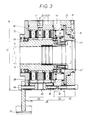
- the device While in the first embodiment of FIGS. 1 and 2, the device is essentially carried by the machine part 11, is in the embodiment 3 and 4, the shaft 10 carrier of the device.
- the device 3 and 4 has substantially the same structure as that Device of the previous embodiment, for what reason the previous description applies. Suffice it to the differences enter into.
- the invention is not limited to that shown Embodiment limited, multiple modifications are possible. So can the measures listed in the characterizing part of claim 1 as well as in the subordinate claims 2 relating thereto to 11 listed additions are also applied to devices, which do not have the sections specified in the preamble of claim 1 Construction on its braking section and a control section connectable to it have. The special one resulting from these measures Flow for effective heat dissipation is also in devices applicable where the control area in the braking area of the device is integrated.
Landscapes
- Engineering & Computer Science (AREA)
- General Engineering & Computer Science (AREA)
- Mechanical Engineering (AREA)
- Braking Arrangements (AREA)
Description
Es zeigen:
- Fig. 1
- einen Axialschnitt durch eine erste Ausführung der erfindungsgemäßen Vorrichtung,
- Fig. 2
- einen Querschnitt durch die Vorrichtung längs der Schnittlinie II-II von Fig. 1,
- Fig. 3
- einen der Fig. 1 entsprechenden Axialschnitt einer abgewandelten Ausführungsform der Vorrichtung nach der Erfindung und
- Fig. 4,
- eine Endansicht der Vorrichtung von Fig. 3.
- 10
- Welle
- 11
- Maschinenteil
- 12
- Axialabstand zwischen 20. 30
- 13
- dritter Axialabschnitt
- 14
- Buchse auf 11, Wellenteil
- 15
- Befestigungseinrichtung für 14
- 16
- Rotations-Pfeil von 11, 14, 21
- 17
- Befestigungsschraube für 20, 30, 40
- 18
- Montageschraube für 28
- 19
- Schraube für 30
- 20
- Bremsabschnitt
- 21
- Lamellenpaket, Innenlamellen-Paket
- 22
- Lamellenpaket, Außenlamellen-Paket
- 23
- zylindrischer Gehäuseteil von 20
- 24
- Mitnahmeprofil für 21
- 25
- Bremseinheit aus 20. 40. 30
- 26
- Halteprofil für 22
- 27
- Anpreßplatte
- 28
- Endplatte von 20
- 29
- Übergangs-Nippel zwischen 51, 53
- 30
- Steuereinheit
- 31
- Kolbenteil
- 32
- Kolbenteil
- 33
- Zylinder
- 34
- erste Druckmittelzuführung für 31
- 35
- zweite Druckmittelzuführung für 32
- 36
- Druckmittelraum für 31
- 37
- Druckmittelraum für 32
- 38, 38'
- Pfeil der Umfangsströmung von 14 (Fig. 2)
- 39
- vordere Stirnfläche von 31
- 40
- Zwischenring
- 41
- Bohrung
- 42
- Druckstück, Bolzen
- 43
- Innenumfang von 21, 22
- 44
- Außenumfang von 21. 22
- 45
- Gewindebohrung
- 46
- Druckpfeil bei 42
- 47
- Rückstellfeder
- 48
- Radialvorsprung, Endbund an 42
- 49
- Axialinnenkanal (Fig. 2)
- 50
- Kühlflüssigkeit, Strömung
- 51
- radiale Zuflußbohrung in 23
- 52
- radiale Abflußbohrung in 23
- 53
- Radialkanal
- 54
- Innenringkanal
- 55
- Ringscheibe in 20
- 56
- erster Strömungszweig von 50
- 57
- zweiter Strömungszweig von 50
- 58, 58'
- Außenringkammer in 28 bzw. 40
- 59
- Axialaußenkammer in 23
- 60
- Ringraum zwischen 14, 23
- 61
- Teilpaket der Lamellen
- 62
- anderes Teilpaket der Lamellen
- 63
- Ringöffnung von 40
- 64
- Schraube (Fig. 3, 4)
- 65
- Eintritt für 50
- 66
- Austritt für 50
- 67
- Wellendichtung bei 40
- 68
- Reihflächennut in 21
- 69
- Wellendichtung bei 66 (Fig. 3)
- 70
- Roll-Lager
- 71
- Außendurchmesser von 20: 40: 30
- 72
- Dichtelement an 42
- 73
- Drehmomentstütze
Claims (19)
- Vorrichtung zum Bremsen einer rotierenden Welle (10) gegenüber einem ruhenden Maschinenteil (11) mittels ineinander greifender Bremsscheiben, wie Lamellen (21, 22) eines Innen- und Außenlamellenpakets,dadurch gekennzeichnet,die in mindestens zwei lösbar miteinander verbindbare Axialabschnitte, nämlich einen Bremsabschnitt (20) und einen Steuerabschnitt (30), gegliedert ist und einen Eintritt (65) sowie einen Austritt (66) für ein Kühlmittel aufweist,wobei der Bremsabschnitt (20) zwischen einem äußeren, zylindrischen Gehäuseteil (23) einerseits und einem inneren zylindrischen Wellenteil (14) andererseits einen Ringraum (60) zum Anordnen der beiden Lamellenpakete (21, 22) aufweist, der axial und radial vom Kühlmittel durchströmt wird,und der Steuerabschnitt (30) mindestens einen durch ein Druckmittel steuerbaren Kolben (31, 32) und einen Zylinder (33) umfaßt und über wenigstens ein Druckstück (42) auf die vor einer axialfesten Endplatte (28) des Bremsabschnitts (20) liegenden Lamellenpakete (21, 22) einwirkt,daß eine Kühlflüssigkeit (50) als Kühlmittel dient und ihr Eintritt (65) sowie Austritt (66) im Umfangsbereich vom zylindrischen Gehäuseteil (23) des Bremsabschnitts (20) angeordnet sind und aus einer die Zylinderwand des Gehäuseteils (23) durchsetzenden Zuflußbohrung (51) bzw. Abflußbohrung (52) gebildet sind,daß ein ruhender Radialkanal (53) in dem Ringraum (60) angeordnet ist und die Zuflußbohrung (51) im Gehäuseteil (23) bis zu einem Innenringkanal (54) verlängert,welcher den Wellenteil (14) in einer Axialzone umschließt und eine Umfangsströmung (38, 38') der Kühlflüssigkeit (50) um den Wellenteil (14) herum bewirkt,daß die Kühlflüssigkeit (50) vom Innenringkanal (54) aus sich zunächst axial entlang des Innenumfangs der Lamellenpakete (21, 22) verteilt,dann durch eine Vielzahl von Nuten (Reibflächennuten) in den einander berührenden Reibflächen der einzelnen Lamellen der beiden Lamellenpakete (21, 22) radial nach außen weiterfließtund sich schließlich am Außenumfang (44) der Lamellenpakete (21, 22) axial sammelt,und daß vom Außenumfang (44) der Lamellenpakete (21, 22) die Abflußbohrung (52) der Kühlflüssigkeit (50) im Gehäuseteil (23) austritt.
- Vorrichtung nach Anspruch 1, dadurch gekennzeichnet, daß vom Innenringkanal (54) aus stellenweise Axialinnenkanäle (49) ausgehen, die zwischen dem Innenumfang (43) der Lamellenpakete (21, 22) und dem Wellenteil (14) angeordnet sind und zur axialen Verteilung (56, 57) der Kühlflüssigkeit (50) dienen.
- Vorrichtung nach Anspruch 1 oder 2, dadurch gekennzeichnet, daß zwischen dem Außenumfang (44) der Lamellenpakete (21, 22) und dem Gehäuseteil (23) stellenweise Axialaußenkammern (59) angeordnet sind, in denen sich die Kühlflüssigkeit (50) sammelt.
- Vorrichtung nach Anspruch 3, dadurch gekennzeichnet, daß die Axialaußenkammern (59) untereinander durch eine Außenringkammer (58, 58') verbunden sind und die Abflußbohrung (52) im Gehäuseteil (23) von einer dieser Axialaußenkammern (59) ausgeht.
- Vorrichtung nach Anspruch 4, dadurch gekennzeichnet, daß eine Ringnut (58, 58') die Außenringkammer bildet und in wenigstens einer der beiden Endplatten (28, 40) eingelassen ist, welche den zur Aufnahme der Lamellenpakete (21, 22) dienenden Ringraum (60) axial begrenzt.
- Vorrichtung nach Anspruch 4, dadurch gekennzeichnet, daß die Axialaußenkammer von einem Ringspalt zwischen dem Außenumfang (44) der Lamellenpakete (21, 22) und dem Gehäuseteil (23) gebildet ist.
- Vorrichtung nach einem oder mehreren der Ansprüche 1 bis 6, dadurch gekennzeichnet, daß die radiale Zuflußbohrung (51) und die radiale Abflußbohrung (52) auf zueinander diametral gegenüberliegenden Umfangsstellen vom Gehäuseteil (23) des Bremsabschnitts (20) angeordnet sind.
- Vorrichtung nach einem oder mehreren der Ansprüche 1 oder 7, dadurch gekennzeichnet, daß der ruhende Radialkanal (53) inmitten der beiden Lamellenpakete (21, 22) angeordnet ist und diese in zwei Teilpakete (61, 62) gliedert, zwischen denen der Innenringkanal (54) angeordnet ist.
- Vorrichtung nach Anspruch 8, dadurch gekennzeichnet, daß der Radialkanal (53) in der Radialmitte der beiden Lamellenpakete (21, 22) angeordnet ist und diese in zwei gleich große Teilpakate (61, 62) gliedert,und die Kühlflüssigkeit (50) vom Radialkanal (53) in zwei zueinander spiegelbildlich gleichen Strömungszweigen (56, 57) bis zur gemeinsamen Abflußbohrung (52) im Gehäuseteil (23) fließt.
- Vorrichtung nach Anspruch 8 oder 9, dadurch gekennzeichnet, daß zwischen den beiden Teilpaketen (61, 62) eine Ringscheibe (55) angeordnet ist, welche durch eine Bohrung zusammen mit Bohrung (51) im Gehäuseteil (23) den ruhenden Radialkanal (53) bildet.
- Vorrichtung nach Anspruch 10, dadurch gekennzeichnet, daß die Ringscheibe (55) einen Radialabstand zum Wellenteil (14) aufweist, und dort den Innenringkanal (54) erzeugt.
- Vorrichtung nach einem oder mehreren der Ansprüche 1 bis 11, dadurch gekennzeichnet, daß als dritter, mittlerer Axialabschnitt (13) eine die Kühlflüssigkeit (50) abdichtende Trennwand zwischen dem Steuerabschnitt (30) und dem Bremsabschnitt (20) angeordnet ist und den Bremsabschnitt (20) zu einer in sich geschlossenen, kühlflüssigkeitsdichten Bremseinheit (74) komplettiert,und die Trennwand stellenweise Durchbrüche (41) besitzt, in denen die Druckstücke (42) mittels Dichtelementen (72) kühlflüssigkeitsdicht aufgenommen sind.
- Vorrichtung nach Anspruch 12, dadurch gekennzeichnet, daß ein Zwischenring (40) den Zylinder (33) der Steuereinheit (30) von dem Gehäuseteil (23) des Bremsabschnitts (20) trennt und eine Schar parallel zur Wellenachse verlaufender Bohrungen (41) aufweist, in welchen die aus Bolzen (42) bestehenden Druckstücke axialgeführt sind.
- Vorrichtung nach Anspruch 13, dadurch gekennzeichnet, daß der Bolzen (42) einen Radialvorsprung (48) aufweist, an dem sich das eine Ende von Rückstellfedern (47) abstützt, während das andere Federende am Zwischenring (40) anliegt.
- Vorrichtung nach einem oder mehreren der Ansprüche 12 bis 14, dadurch gekennzeichnet, daß zwischen den Lamellenpaketen (21, 22) einerseits und den Druckstücken bzw. den Bolzen (42) andererseits eine mitbewegliche Anpreßplatte (27) angeordnet ist.
- Vorrichtung nach einem oder mehreren der Ansprüche 1 bis 15, dadurch gekennzeichnet, daß der Zylinder (33) des Steuerabschnitts (30) einen Stufenkolben (31, 32) besitzt, dessen beide Druckmittelräume (36, 37) mit je einer Druckmittelzuführung (34, 35) versehen sind.
- Vorrichtung nach einem oder mehreren der Ansprüche 1 bis 16, dadurch gekennzeichnet, daß der Zwischenring (40) zwar am Gehäuseteil (23) des Bremsabschnitts (20) festgeschraubt ist, aber Schraubbefestigungsmittel (45; 19) zum Anschluß des Steuerabschnitts (30) aufweist.
- Vorrichtung nach einem oder mehreren der Ansprüche 1 bis 17, dadurch gekennzeichnet, daß der zylindrische Gehäuseteil (23) des Bremsabschnitts (20) einen Außendurchmesser (71) aufweist, welcher sowohl dem Außendurchmesser des Zwischenrings (40) als auch dem Außendurchmesser vom Zylinder (33) des Steuerabschnitts (30) im wesentlichen gleich ist.
- Vorrichtung nach einem oder mehreren der Ansprüche 1 bis 18, dadurch gekennzeichnet, daß die Trennwand mehrgliedrig ausgebildet ist und, außer dem Zwischenring (40), eine Wellendichtung (67) aufweist, die einen Radialabstand zwischen der Ringöffnung (63) des Zwischenrings (40) einerseits und einem vorzugsweise abgesetzten Ende des Wellenteils (14) andererseits flüssigkeitsdicht überbrückt, (Fig. 1).
Applications Claiming Priority (2)
| Application Number | Priority Date | Filing Date | Title |
|---|---|---|---|
| DE4401372 | 1994-01-19 | ||
| DE4401372A DE4401372C2 (de) | 1994-01-19 | 1994-01-19 | Lamellenbremse zur Dauerbremsung einer rotierenden Welle gegenüber einem ruhendem Maschinenteil |
Publications (2)
| Publication Number | Publication Date |
|---|---|
| EP0664412A1 EP0664412A1 (de) | 1995-07-26 |
| EP0664412B1 true EP0664412B1 (de) | 1998-04-22 |
Family
ID=6508190
Family Applications (1)
| Application Number | Title | Priority Date | Filing Date |
|---|---|---|---|
| EP95100471A Expired - Lifetime EP0664412B1 (de) | 1994-01-19 | 1995-01-14 | Vorrichtung zum Bremsen einer rotierenden Welle gegenüber einem ruhenden Maschinenteil |
Country Status (3)
| Country | Link |
|---|---|
| EP (1) | EP0664412B1 (de) |
| DE (2) | DE4401372C2 (de) |
| ES (1) | ES2115272T3 (de) |
Families Citing this family (5)
| Publication number | Priority date | Publication date | Assignee | Title |
|---|---|---|---|---|
| DE19648064C1 (de) * | 1996-11-20 | 1998-06-10 | Kidde Ind Inc | Lamellenbremse mit logarithmischer Kennlinie |
| DE102009023128B4 (de) * | 2009-05-20 | 2012-04-19 | Stromag Ag | Verfahren zum Herstellen eines Außenkörpers einer Lamellenbremse |
| DE102016216300A1 (de) * | 2016-08-30 | 2018-03-01 | Zf Friedrichshafen Ag | Lamellenbremse |
| CN106800060B (zh) * | 2016-12-31 | 2019-10-25 | 李友洪 | 制动机构 |
| CZ310195B6 (cs) * | 2023-09-04 | 2024-11-06 | Josef Bernard | Osová, kapalinou chlazená brzda |
Family Cites Families (5)
| Publication number | Priority date | Publication date | Assignee | Title |
|---|---|---|---|---|
| FR980742A (fr) * | 1943-02-17 | 1951-05-17 | Automobiles Unic Soc Nouv | Perfectionnements aux appareils ralentisseurs à friction pour véhicules automobiles |
| US3999634A (en) * | 1974-01-14 | 1976-12-28 | Howell Industries, Inc. | Pneumatic actuation for disc brake assemblies |
| GB1504073A (en) * | 1975-08-27 | 1978-03-15 | Caterpillar Tractor Co | Annular single piston brake arrangement |
| US4146116A (en) * | 1977-09-15 | 1979-03-27 | Rockwell International Corporation | Friction brake |
| IT1215200B (it) * | 1986-11-28 | 1990-01-31 | Iveco Fiat S P A E | Dispositivo rallentatore per veicoli industriali |
-
1994
- 1994-01-19 DE DE4401372A patent/DE4401372C2/de not_active Expired - Fee Related
-
1995
- 1995-01-14 DE DE59501944T patent/DE59501944D1/de not_active Expired - Fee Related
- 1995-01-14 ES ES95100471T patent/ES2115272T3/es not_active Expired - Lifetime
- 1995-01-14 EP EP95100471A patent/EP0664412B1/de not_active Expired - Lifetime
Also Published As
| Publication number | Publication date |
|---|---|
| DE4401372C2 (de) | 1997-10-02 |
| DE59501944D1 (de) | 1998-05-28 |
| EP0664412A1 (de) | 1995-07-26 |
| DE4401372A1 (de) | 1995-07-20 |
| ES2115272T3 (es) | 1998-06-16 |
Similar Documents
| Publication | Publication Date | Title |
|---|---|---|
| DE60026335T2 (de) | Einheit von flugzeugrad, bremse und achse für ein rein elektrisches flugzeugbremssystem | |
| DE3013431C2 (de) | Radkopf für Triebräder von Fahrzeugen | |
| DE2010713C3 (de) | Druckmittelbetätigte Reibungs-Kupplungs- und Bremsvorrichtung für ein Schwungrad | |
| EP2841763B1 (de) | Radialkolbenmotor mit bremse | |
| DE4022527A1 (de) | Fluessigkeitsgekuehlte bremsvorrichtung | |
| DE60027233T2 (de) | Einrichtung zum Bremsen eines Rotors gegenüber einem Stator | |
| DE3733438A1 (de) | Fluessigkeitsgekuehlte scheibenbremse | |
| EP0143898A1 (de) | Reibungsbremse bzw. -kupplung mit einer Zwangskühlung | |
| DE3106374C2 (de) | Teilbelag-Scheibenbremse | |
| DE2706806A1 (de) | Nasse scheibenbremse | |
| DE3732760A1 (de) | Reibungsbremse mit fluessigkeitskuehlung | |
| DE1555023A1 (de) | Bremseinrichtung | |
| DE102019133510A1 (de) | Kupplungsvorrichtung | |
| DE3339659C2 (de) | ||
| DE2944008C2 (de) | Druckmittelbetätigte Reibscheibenkupplungs- und Bremseinheit | |
| DE102018131958A1 (de) | Bremssystem mit einem Bremszylinder mit mehreren Druckkolben; sowie elektrische Radantriebseinheit | |
| DE19636508A1 (de) | Radialkolbenpumpe mit einseitig geschlossener Lagerschale des Radiallagers | |
| EP1038102B1 (de) | Radialkolbenmotor mit reibschlussbremse | |
| EP0161240B1 (de) | Anordnung einer bremse in einem radkopf | |
| EP0664412A1 (de) | Vorrichtung zum Bremsen einer rotierenden Welle gegenüber einem ruhenden Maschinenteil | |
| DE102017204451A1 (de) | Getriebe, insbesondere für Antriebsstrang von Schienenfahrzeugen | |
| DE19730718B4 (de) | Mehrscheiben-Trockenkupplung | |
| DE102018130817B4 (de) | Bremssystem mit einem konzentrischen Bremszylinder; sowie elektrische Radantriebseinheit | |
| DE2711505A1 (de) | Kombinierte kupplungs- und doppelbremsvorrichtung | |
| DE9400821U1 (de) | Vorrichtung zur Dauerbremsung einer rotierenden Welle in Prüfständen, Abrolleinrichtungen o.dgl. |
Legal Events
| Date | Code | Title | Description |
|---|---|---|---|
| PUAI | Public reference made under article 153(3) epc to a published international application that has entered the european phase |
Free format text: ORIGINAL CODE: 0009012 |
|
| AK | Designated contracting states |
Kind code of ref document: A1 Designated state(s): DE ES FR GB IT |
|
| 17P | Request for examination filed |
Effective date: 19960111 |
|
| GRAG | Despatch of communication of intention to grant |
Free format text: ORIGINAL CODE: EPIDOS AGRA |
|
| GRAG | Despatch of communication of intention to grant |
Free format text: ORIGINAL CODE: EPIDOS AGRA |
|
| GRAH | Despatch of communication of intention to grant a patent |
Free format text: ORIGINAL CODE: EPIDOS IGRA |
|
| 17Q | First examination report despatched |
Effective date: 19970911 |
|
| GRAH | Despatch of communication of intention to grant a patent |
Free format text: ORIGINAL CODE: EPIDOS IGRA |
|
| ITF | It: translation for a ep patent filed | ||
| GRAA | (expected) grant |
Free format text: ORIGINAL CODE: 0009210 |
|
| AK | Designated contracting states |
Kind code of ref document: B1 Designated state(s): DE ES FR GB IT |
|
| PG25 | Lapsed in a contracting state [announced via postgrant information from national office to epo] |
Ref country code: GB Free format text: LAPSE BECAUSE OF FAILURE TO SUBMIT A TRANSLATION OF THE DESCRIPTION OR TO PAY THE FEE WITHIN THE PRESCRIBED TIME-LIMIT Effective date: 19980422 Ref country code: FR Free format text: LAPSE BECAUSE OF FAILURE TO SUBMIT A TRANSLATION OF THE DESCRIPTION OR TO PAY THE FEE WITHIN THE PRESCRIBED TIME-LIMIT Effective date: 19980422 |
|
| REF | Corresponds to: |
Ref document number: 59501944 Country of ref document: DE Date of ref document: 19980528 |
|
| REG | Reference to a national code |
Ref country code: ES Ref legal event code: FG2A Ref document number: 2115272 Country of ref document: ES Kind code of ref document: T3 |
|
| EN | Fr: translation not filed | ||
| GBV | Gb: ep patent (uk) treated as always having been void in accordance with gb section 77(7)/1977 [no translation filed] |
Effective date: 19980422 |
|
| PLBE | No opposition filed within time limit |
Free format text: ORIGINAL CODE: 0009261 |
|
| STAA | Information on the status of an ep patent application or granted ep patent |
Free format text: STATUS: NO OPPOSITION FILED WITHIN TIME LIMIT |
|
| 26N | No opposition filed | ||
| PGFP | Annual fee paid to national office [announced via postgrant information from national office to epo] |
Ref country code: DE Payment date: 20040106 Year of fee payment: 10 |
|
| PGFP | Annual fee paid to national office [announced via postgrant information from national office to epo] |
Ref country code: ES Payment date: 20040115 Year of fee payment: 10 |
|
| PG25 | Lapsed in a contracting state [announced via postgrant information from national office to epo] |
Ref country code: IT Free format text: LAPSE BECAUSE OF NON-PAYMENT OF DUE FEES;WARNING: LAPSES OF ITALIAN PATENTS WITH EFFECTIVE DATE BEFORE 2007 MAY HAVE OCCURRED AT ANY TIME BEFORE 2007. THE CORRECT EFFECTIVE DATE MAY BE DIFFERENT FROM THE ONE RECORDED. Effective date: 20050114 |
|
| PG25 | Lapsed in a contracting state [announced via postgrant information from national office to epo] |
Ref country code: ES Free format text: LAPSE BECAUSE OF NON-PAYMENT OF DUE FEES Effective date: 20050115 |
|
| PG25 | Lapsed in a contracting state [announced via postgrant information from national office to epo] |
Ref country code: DE Free format text: LAPSE BECAUSE OF NON-PAYMENT OF DUE FEES Effective date: 20050802 |
|
| REG | Reference to a national code |
Ref country code: ES Ref legal event code: FD2A Effective date: 20050115 |