EP0664210A1 - Cold formable metal sheet sandwich with thermosettable core, method for its shaping and structural element obtained therewith - Google Patents
Cold formable metal sheet sandwich with thermosettable core, method for its shaping and structural element obtained therewith Download PDFInfo
- Publication number
- EP0664210A1 EP0664210A1 EP94120080A EP94120080A EP0664210A1 EP 0664210 A1 EP0664210 A1 EP 0664210A1 EP 94120080 A EP94120080 A EP 94120080A EP 94120080 A EP94120080 A EP 94120080A EP 0664210 A1 EP0664210 A1 EP 0664210A1
- Authority
- EP
- European Patent Office
- Prior art keywords
- polymeric adhesive
- sheet
- panel
- metal elements
- composite material
- Prior art date
- Legal status (The legal status is an assumption and is not a legal conclusion. Google has not performed a legal analysis and makes no representation as to the accuracy of the status listed.)
- Granted
Links
Images


Classifications
-
- B—PERFORMING OPERATIONS; TRANSPORTING
- B32—LAYERED PRODUCTS
- B32B—LAYERED PRODUCTS, i.e. PRODUCTS BUILT-UP OF STRATA OF FLAT OR NON-FLAT, e.g. CELLULAR OR HONEYCOMB, FORM
- B32B15/00—Layered products comprising a layer of metal
- B32B15/14—Layered products comprising a layer of metal next to a fibrous or filamentary layer
-
- B—PERFORMING OPERATIONS; TRANSPORTING
- B29—WORKING OF PLASTICS; WORKING OF SUBSTANCES IN A PLASTIC STATE IN GENERAL
- B29C—SHAPING OR JOINING OF PLASTICS; SHAPING OF MATERIAL IN A PLASTIC STATE, NOT OTHERWISE PROVIDED FOR; AFTER-TREATMENT OF THE SHAPED PRODUCTS, e.g. REPAIRING
- B29C70/00—Shaping composites, i.e. plastics material comprising reinforcements, fillers or preformed parts, e.g. inserts
- B29C70/04—Shaping composites, i.e. plastics material comprising reinforcements, fillers or preformed parts, e.g. inserts comprising reinforcements only, e.g. self-reinforcing plastics
- B29C70/26—Non-fibrous reinforcements only
-
- B—PERFORMING OPERATIONS; TRANSPORTING
- B29—WORKING OF PLASTICS; WORKING OF SUBSTANCES IN A PLASTIC STATE IN GENERAL
- B29C—SHAPING OR JOINING OF PLASTICS; SHAPING OF MATERIAL IN A PLASTIC STATE, NOT OTHERWISE PROVIDED FOR; AFTER-TREATMENT OF THE SHAPED PRODUCTS, e.g. REPAIRING
- B29C70/00—Shaping composites, i.e. plastics material comprising reinforcements, fillers or preformed parts, e.g. inserts
- B29C70/04—Shaping composites, i.e. plastics material comprising reinforcements, fillers or preformed parts, e.g. inserts comprising reinforcements only, e.g. self-reinforcing plastics
- B29C70/28—Shaping operations therefor
- B29C70/30—Shaping by lay-up, i.e. applying fibres, tape or broadsheet on a mould, former or core; Shaping by spray-up, i.e. spraying of fibres on a mould, former or core
- B29C70/34—Shaping by lay-up, i.e. applying fibres, tape or broadsheet on a mould, former or core; Shaping by spray-up, i.e. spraying of fibres on a mould, former or core and shaping or impregnating by compression, i.e. combined with compressing after the lay-up operation
- B29C70/345—Shaping by lay-up, i.e. applying fibres, tape or broadsheet on a mould, former or core; Shaping by spray-up, i.e. spraying of fibres on a mould, former or core and shaping or impregnating by compression, i.e. combined with compressing after the lay-up operation using matched moulds
-
- B—PERFORMING OPERATIONS; TRANSPORTING
- B32—LAYERED PRODUCTS
- B32B—LAYERED PRODUCTS, i.e. PRODUCTS BUILT-UP OF STRATA OF FLAT OR NON-FLAT, e.g. CELLULAR OR HONEYCOMB, FORM
- B32B15/00—Layered products comprising a layer of metal
- B32B15/04—Layered products comprising a layer of metal comprising metal as the main or only constituent of a layer, which is next to another layer of the same or of a different material
- B32B15/08—Layered products comprising a layer of metal comprising metal as the main or only constituent of a layer, which is next to another layer of the same or of a different material of synthetic resin
-
- B—PERFORMING OPERATIONS; TRANSPORTING
- B32—LAYERED PRODUCTS
- B32B—LAYERED PRODUCTS, i.e. PRODUCTS BUILT-UP OF STRATA OF FLAT OR NON-FLAT, e.g. CELLULAR OR HONEYCOMB, FORM
- B32B37/00—Methods or apparatus for laminating, e.g. by curing or by ultrasonic bonding
- B32B37/12—Methods or apparatus for laminating, e.g. by curing or by ultrasonic bonding characterised by using adhesives
- B32B37/1207—Heat-activated adhesive
-
- B—PERFORMING OPERATIONS; TRANSPORTING
- B32—LAYERED PRODUCTS
- B32B—LAYERED PRODUCTS, i.e. PRODUCTS BUILT-UP OF STRATA OF FLAT OR NON-FLAT, e.g. CELLULAR OR HONEYCOMB, FORM
- B32B38/00—Ancillary operations in connection with laminating processes
-
- B—PERFORMING OPERATIONS; TRANSPORTING
- B32—LAYERED PRODUCTS
- B32B—LAYERED PRODUCTS, i.e. PRODUCTS BUILT-UP OF STRATA OF FLAT OR NON-FLAT, e.g. CELLULAR OR HONEYCOMB, FORM
- B32B5/00—Layered products characterised by the non- homogeneity or physical structure, i.e. comprising a fibrous, filamentary, particulate or foam layer; Layered products characterised by having a layer differing constitutionally or physically in different parts
- B32B5/02—Layered products characterised by the non- homogeneity or physical structure, i.e. comprising a fibrous, filamentary, particulate or foam layer; Layered products characterised by having a layer differing constitutionally or physically in different parts characterised by structural features of a fibrous or filamentary layer
- B32B5/022—Non-woven fabric
-
- B—PERFORMING OPERATIONS; TRANSPORTING
- B32—LAYERED PRODUCTS
- B32B—LAYERED PRODUCTS, i.e. PRODUCTS BUILT-UP OF STRATA OF FLAT OR NON-FLAT, e.g. CELLULAR OR HONEYCOMB, FORM
- B32B5/00—Layered products characterised by the non- homogeneity or physical structure, i.e. comprising a fibrous, filamentary, particulate or foam layer; Layered products characterised by having a layer differing constitutionally or physically in different parts
- B32B5/02—Layered products characterised by the non- homogeneity or physical structure, i.e. comprising a fibrous, filamentary, particulate or foam layer; Layered products characterised by having a layer differing constitutionally or physically in different parts characterised by structural features of a fibrous or filamentary layer
- B32B5/024—Woven fabric
-
- B—PERFORMING OPERATIONS; TRANSPORTING
- B32—LAYERED PRODUCTS
- B32B—LAYERED PRODUCTS, i.e. PRODUCTS BUILT-UP OF STRATA OF FLAT OR NON-FLAT, e.g. CELLULAR OR HONEYCOMB, FORM
- B32B7/00—Layered products characterised by the relation between layers; Layered products characterised by the relative orientation of features between layers, or by the relative values of a measurable parameter between layers, i.e. products comprising layers having different physical, chemical or physicochemical properties; Layered products characterised by the interconnection of layers
- B32B7/04—Interconnection of layers
- B32B7/12—Interconnection of layers using interposed adhesives or interposed materials with bonding properties
-
- B—PERFORMING OPERATIONS; TRANSPORTING
- B32—LAYERED PRODUCTS
- B32B—LAYERED PRODUCTS, i.e. PRODUCTS BUILT-UP OF STRATA OF FLAT OR NON-FLAT, e.g. CELLULAR OR HONEYCOMB, FORM
- B32B2305/00—Condition, form or state of the layers or laminate
- B32B2305/08—Reinforcements
-
- B—PERFORMING OPERATIONS; TRANSPORTING
- B32—LAYERED PRODUCTS
- B32B—LAYERED PRODUCTS, i.e. PRODUCTS BUILT-UP OF STRATA OF FLAT OR NON-FLAT, e.g. CELLULAR OR HONEYCOMB, FORM
- B32B2305/00—Condition, form or state of the layers or laminate
- B32B2305/74—Partially cured
-
- B—PERFORMING OPERATIONS; TRANSPORTING
- B32—LAYERED PRODUCTS
- B32B—LAYERED PRODUCTS, i.e. PRODUCTS BUILT-UP OF STRATA OF FLAT OR NON-FLAT, e.g. CELLULAR OR HONEYCOMB, FORM
- B32B2311/00—Metals, their alloys or their compounds
-
- B—PERFORMING OPERATIONS; TRANSPORTING
- B32—LAYERED PRODUCTS
- B32B—LAYERED PRODUCTS, i.e. PRODUCTS BUILT-UP OF STRATA OF FLAT OR NON-FLAT, e.g. CELLULAR OR HONEYCOMB, FORM
- B32B2375/00—Polyureas; Polyurethanes
-
- B—PERFORMING OPERATIONS; TRANSPORTING
- B32—LAYERED PRODUCTS
- B32B—LAYERED PRODUCTS, i.e. PRODUCTS BUILT-UP OF STRATA OF FLAT OR NON-FLAT, e.g. CELLULAR OR HONEYCOMB, FORM
- B32B2605/00—Vehicles
- B32B2605/08—Cars
-
- F—MECHANICAL ENGINEERING; LIGHTING; HEATING; WEAPONS; BLASTING
- F02—COMBUSTION ENGINES; HOT-GAS OR COMBUSTION-PRODUCT ENGINE PLANTS
- F02F—CYLINDERS, PISTONS OR CASINGS, FOR COMBUSTION ENGINES; ARRANGEMENTS OF SEALINGS IN COMBUSTION ENGINES
- F02F7/00—Casings, e.g. crankcases or frames
- F02F7/006—Camshaft or pushrod housings
Definitions
- the present invention relates to a method for the forming of an element of composite material usable, for example, as a structural element of a vehicle.
- Laminated elements of composite material are known and are formed from pairs of thin metal sheets, for example, both of steel or of aluminium, or one of steel and the other of aluminium, between which a layer of polymeric adhesive is interposed.
- These composite elements have good mechanical strength characteristics and good insulating properties insulators against heat, noise and vibrations, as well as quite low weight, and are thus often used as structural elements in the construction of vehicles, particularly near regions which are subject to considerable temperatures or vibrations.
- Sheet-metal sandwiches are generally produced and marketed by the producers of sheet-steel or aluminium, who produce and sell them directly in the form of large rolls or "coils" each made from a pair of metal sheets connected by means of an intermediate layer of polymeric adhesive, which is already polymerized in the product sold.
- the composite elements which can be produced by the subdivision of the coils have disadvantages because their maximum dimensions are limited by the standard dimensions of the coils and it is thus not always possible to produce individual elements having optimal dimensions to form structural elements, for example, of vehicles, from the coils. Moreover, these composite elements are not very suitable for undergoing the mechanical operations which are necessary to shape them for use.
- panels made from the known sheet-metal sandwiches are not very suitable for pressing since, during the pressing step, relative slippage occurs between the outer sheets of the panel, causing separation of the intermediate layer of polymerized adhesive, thus worsening the mechanical and insulating characteristics of the panel. For this reason, these known panels are generally subjected only to mechanical bending operations. Moreover, they are difficult to weld and any welding operations may damage the intermediate layer of polymeric adhesive.
- the main object of the present invention is to propose a method of forming an element of composite material which prevents the problems mentioned above.
- a further subject of the invention is a structural element of composite material, particularly for a vehicle, formed by means of the method of the invention.
- Another subject of the invention is a panel of composite material including a pair of sheet-metal elements between which a non-polymerized polymeric adhesive is interposed, characterized in that it is intended to be subjected to a mechanical cold-forming step, and in that the polymeric adhesive can be polymerized completely only after the step in which the panel is formed.
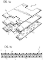
- a panel 3 of composite material is made from a pair of shaped sheet-metal elements 5 and 7, between which a non-polymerized polymeric adhesive 11 is interposed.
- An intermediate reinforcing layer 9, preferably shaped in the same manner as the elements 5 and 7, is preferably interposed between the sheet-metal elements 5 and 7, and is constituted, for example, by woven or non-woven carbon, glass or aramide fibres.
- the metal sheets 5 and 7 may be treated beforehand to eliminate traces of grease or of various impurities, and of moisture, in order to favour the adhesion of the polymeric adhesive 11 thereto. In particular, they may be subjected to a first pickling step, after which a primer or a priming coat may be applied. If the metal sheets 5 and 7 are galvanized or pre-painted, it is not necessary to use the primer, since the polymeric adhesive 11 adheres very well to the surfaces of metal sheets thus treated.
- the polymeric adhesive 11 is then applied to one of the metal sheets 5 and 7, if the layer 9 is not present, whereas, if the intermediate layer 9 is present, the polymeric adhesive 11 is applied to both of the metal sheets 5 and 7 on their surfaces which are intended to face towards the reinforcing layer 9, so that the adhesive 11 is interposed between the metal sheets and the layer 9.
- the polymeric adhesive 11 used may be a thermosetting adhesive mainly when the final structural element is to have good mechanical characteristics and good resistance to heat.
- a thermoplastic polymeric adhesive may be used when a certain resistance to noise or vibrations is required.
- Thermoplastic adhesive has the advantage of being recyclable, but has the disadvantage of being more expensive than thermosetting adhesives.
- the adhesive 11 can be applied essentially roughly without the need to use additional steps to spread it uniformly, for example, it can be supplied in a plurality of distinct piles or heaps, automatically or with a static mixing gun.
- the intermediate layer 9 may be constituted by a sheet of strong fibres already impregnated with the polymeric adhesive 11.
- products which are already known and marketed by firms operating in the field and which, for example, are available in the form of glass-wool sheets impregnated with a polyurethane, epoxy, or other adhesive so as to be rendered adhesive on both sides, may also be used.
- the sheet-metal elements 5 and 7 and any intermediate layer 9 are then placed side by side and the composite panel 3 thus obtained can be disposed in a double-acting press to undergo a mechanical cold-forming step, for example, a primary drawing step.
- Figure 2 shows a drawing die, indicated 15, comprising a hollow matrix 17 and a punch 19 which is movable vertically (with reference to the drawing).
- the die 15 comprises a pressure bar 21 for keeping the panel 3 firmly in position during the drawing step.
- automatic clamping devices for example, of the known type called "clinching" devices, two of which are indicated 23 in Figure 2, are preferably used.
- Each device 23 comprises a piston 25 slidable in the matrix 17 along a line perpendicular to the panel 3 at the edges thereof.
- Each piston 25 has a conical head 25a facing the panel 3 and an opposite end facing a chamber into which a pressurized fluid is supplied through a delivery duct 24.
- the pressure bar 21 has seats corresponding to the pistons 25, each comprising a plurality of lateral elements 27 which define each seat and are articulated at 27a, and which can move apart as a result of the approach of the conical head 25a of the piston 25.
- the pressurized fluid is supplied through the ducts 24 in order to move the pistons 25 towards the panel 23.
- the heads 25a extend through the panel 3 also causing angular displacement of the elements 27 so that holes with upset edges 29 are formed along the edges of the panel 3.
- the upset edges 29 enable the elements 5, 7 and 9 which make up the panel 3 to be held firmly in their respective positions during the drawing step.
- the punch 19 is then moved towards the matrix 17 to carry out the primary drawing step, during which the polymeric adhesive 11 is automatically spread uniformly within the panel 3.
- the die 15 may have internal heating devices such as, for example, a plurality of ducts 30a, 30b, in the matrix 17 and in the punch 15, respectively, into which a heating fluid, for example, oil at about 70°C is supplied, or in which there may be electrical resistances so that, already during the pressing step, the polymeric adhesive 11 undergoes heating such as to bring about partial polymerization.
- a heating fluid for example, oil at about 70°C is supplied, or in which there may be electrical resistances so that, already during the pressing step, the polymeric adhesive 11 undergoes heating such as to bring about partial polymerization.
- the adhesive 11 is in any case subjected to limited pre-polymerization as a result of the heat developed during the pressing step because of the mechanical pressures and stresses involved.
- the panel 3 Upon completion of the forming step, the panel 3 is removed from the die 15 and undergoes a process to polymerize the polymeric adhesive, for example, it is placed in an oven, typically for a period of about 30 minutes, at a temperature of about 150°C, until the adhesive has fully polymerized.
- the panel 3 can then undergo any subsequent finishing steps such as, for example, further edge-trimming or blanking steps, etc.
- the optimal amount of adhesive 11 to use is determined in dependence on various parameters, for example, the tensile strength envisaged for the panel 3 in use, the required capacity for insulation against heat and/or noise and/or vibrations, and the required shear strength. Naturally, account will also be taken of the viscosity of the adhesive, of the pressure to which the panel is subject during the pressing step, and of the final gap which will be present between the matrix 17 and the punch 19 during the pressing step.
- panels thus produced may be used on motor vehicles to form insulating partitions, for example, between the floor and the catalytic converter, between the engine compartment and the passenger compartment of the motor vehicle, or for the partition under the dashboard .
- the rocker cover of the engine and structural elements such as the body pillars may also be produced with a panel of this type.
- the elements of composite material according to the invention may be used whenever elements with good mechanical properties and low weight intended for insulation against heat and/or noise and/or vibrations are to be produced.
- the polymeric adhesive is a two-part structural polyurethane adhesive comprising a resin A and a resin B of the type which is particularly suitable for automated supply or for supply by two-part static mixing guns.
- the components A and B are resins derived from complex mixtures which comprise the following percentages by weight:
- the shear peel strength of the adhesive after it has undergone a polymerization process with a cycle of 10 minutes at 80°C and 7 days at ambient temperature will be:
- a primer is used to improve the adhesion and moisture resistance of the polymeric adhesive, it may be of the polyurethane, polysulphide, silicon on glass, or metal type and will require drying for about 30 minutes.
Abstract
Description
- The present invention relates to a method for the forming of an element of composite material usable, for example, as a structural element of a vehicle.
- Laminated elements of composite material, generally known as "sheet-metal sandwiches", are known and are formed from pairs of thin metal sheets, for example, both of steel or of aluminium, or one of steel and the other of aluminium, between which a layer of polymeric adhesive is interposed.
- These composite elements have good mechanical strength characteristics and good insulating properties insulators against heat, noise and vibrations, as well as quite low weight, and are thus often used as structural elements in the construction of vehicles, particularly near regions which are subject to considerable temperatures or vibrations.
- Sheet-metal sandwiches are generally produced and marketed by the producers of sheet-steel or aluminium, who produce and sell them directly in the form of large rolls or "coils" each made from a pair of metal sheets connected by means of an intermediate layer of polymeric adhesive, which is already polymerized in the product sold.
- The composite elements which can be produced by the subdivision of the coils, however, have disadvantages because their maximum dimensions are limited by the standard dimensions of the coils and it is thus not always possible to produce individual elements having optimal dimensions to form structural elements, for example, of vehicles, from the coils. Moreover, these composite elements are not very suitable for undergoing the mechanical operations which are necessary to shape them for use.
- In particular, panels made from the known sheet-metal sandwiches are not very suitable for pressing since, during the pressing step, relative slippage occurs between the outer sheets of the panel, causing separation of the intermediate layer of polymerized adhesive, thus worsening the mechanical and insulating characteristics of the panel. For this reason, these known panels are generally subjected only to mechanical bending operations. Moreover, they are difficult to weld and any welding operations may damage the intermediate layer of polymeric adhesive.
- The main object of the present invention is to propose a method of forming an element of composite material which prevents the problems mentioned above.
- This object is achieved, according to the invention, by virtue of the fact that the method comprises the following steps:
- providing a pair of sheet-metal elements,
- interposing a non-polymerised polymeric adhesive between the sheet-metal elements,
- joining the sheet-metal elements together with the polymeric adhesive interposed so as to form a panel of composite material,
- subjecting the panel to a cold-forming step in order to form the element of composite material, and
- subjecting the element of composite material produced to a process to polymerize the polymeric adhesive.
- By virtue of these characteristics, it is possible to produce panels and structural elements of the desired sizes and shapes, which can be subjected to mechanical cold-forming operations of any type, for example, pressing or drawing, without the intermediate polymeric layer being damaged during the forming step since it is not polymerized and permits relative movements between the sheet-metal elements which can therefore deform freely. Moreover, the elements of composite material thus produced withstand welding operations without problems.
- A further subject of the invention is a structural element of composite material, particularly for a vehicle, formed by means of the method of the invention.
- Another subject of the invention is a panel of composite material including a pair of sheet-metal elements between which a non-polymerized polymeric adhesive is interposed, characterized in that it is intended to be subjected to a mechanical cold-forming step, and in that the polymeric adhesive can be polymerized completely only after the step in which the panel is formed.
- Further characteristics and advantages of the present invention will become clearer from the following detailed description given with reference to the appended drawings, which are provided purely by way of non-limiting example, in which:
- Figure 1a is a schematic, perspective view of a plurality of elements which are intended to be joined together in order to form a panel of composite material,
- Figure 1b is a sectioned, elevational view of the elements of Figure 1a placed side by side,
- Figure 2 is a sectioned side elevational view of the panel of Figure 1b undergoing a cold mechanical forming step by pressing, and
- Figure 3 is a perspective view of the panel of Figure 2 after the pressing step.
- With reference to the drawings, a
panel 3 of composite material is made from a pair of shaped sheet-metal elements polymeric adhesive 11 is interposed. - An intermediate reinforcing
layer 9, preferably shaped in the same manner as theelements metal elements - The
metal sheets polymeric adhesive 11 thereto. In particular, they may be subjected to a first pickling step, after which a primer or a priming coat may be applied. If themetal sheets polymeric adhesive 11 adheres very well to the surfaces of metal sheets thus treated. - The
polymeric adhesive 11 is then applied to one of themetal sheets layer 9 is not present, whereas, if theintermediate layer 9 is present, thepolymeric adhesive 11 is applied to both of themetal sheets layer 9, so that theadhesive 11 is interposed between the metal sheets and thelayer 9. - The
polymeric adhesive 11 used may be a thermosetting adhesive mainly when the final structural element is to have good mechanical characteristics and good resistance to heat. Alternatively, a thermoplastic polymeric adhesive may be used when a certain resistance to noise or vibrations is required. Thermoplastic adhesive has the advantage of being recyclable, but has the disadvantage of being more expensive than thermosetting adhesives. - The
adhesive 11 can be applied essentially roughly without the need to use additional steps to spread it uniformly, for example, it can be supplied in a plurality of distinct piles or heaps, automatically or with a static mixing gun. - Alternatively, the
intermediate layer 9 may be constituted by a sheet of strong fibres already impregnated with thepolymeric adhesive 11. In this case products which are already known and marketed by firms operating in the field and which, for example, are available in the form of glass-wool sheets impregnated with a polyurethane, epoxy, or other adhesive so as to be rendered adhesive on both sides, may also be used. - The sheet-
metal elements intermediate layer 9 are then placed side by side and thecomposite panel 3 thus obtained can be disposed in a double-acting press to undergo a mechanical cold-forming step, for example, a primary drawing step. - Figure 2 shows a drawing die, indicated 15, comprising a
hollow matrix 17 and apunch 19 which is movable vertically (with reference to the drawing). The die 15 comprises apressure bar 21 for keeping thepanel 3 firmly in position during the drawing step. - To allow optimal relative positioning of the
elements panel 3 during the drawing step and, in particular, to prevent relative slippage between the elements, automatic clamping devices, for example, of the known type called "clinching" devices, two of which are indicated 23 in Figure 2, are preferably used. - Each
device 23 comprises apiston 25 slidable in thematrix 17 along a line perpendicular to thepanel 3 at the edges thereof. Eachpiston 25 has aconical head 25a facing thepanel 3 and an opposite end facing a chamber into which a pressurized fluid is supplied through adelivery duct 24. Thepressure bar 21 has seats corresponding to thepistons 25, each comprising a plurality oflateral elements 27 which define each seat and are articulated at 27a, and which can move apart as a result of the approach of theconical head 25a of thepiston 25. Before thepunch 19 moves towards thematrix 17 and after thepanel 3 has been clamped by means of thepressure bar 21, the pressurized fluid is supplied through theducts 24 in order to move thepistons 25 towards thepanel 23. Theheads 25a extend through thepanel 3 also causing angular displacement of theelements 27 so that holes withupset edges 29 are formed along the edges of thepanel 3. Theupset edges 29 enable theelements panel 3 to be held firmly in their respective positions during the drawing step. - The
punch 19 is then moved towards thematrix 17 to carry out the primary drawing step, during which thepolymeric adhesive 11 is automatically spread uniformly within thepanel 3. - If a thermosetting
polymeric adhesive 11 is used, the die 15 may have internal heating devices such as, for example, a plurality ofducts 30a, 30b, in thematrix 17 and in thepunch 15, respectively, into which a heating fluid, for example, oil at about 70°C is supplied, or in which there may be electrical resistances so that, already during the pressing step, thepolymeric adhesive 11 undergoes heating such as to bring about partial polymerization. Theadhesive 11 is in any case subjected to limited pre-polymerization as a result of the heat developed during the pressing step because of the mechanical pressures and stresses involved. - Naturally, it is also possible to use a pressing device other than that shown, for example, including an elastomeric punch, so as further to favour the drawing of the panel, considerably reducing the local tensions generated in the course of the forming step.
- Upon completion of the forming step, the
panel 3 is removed from thedie 15 and undergoes a process to polymerize the polymeric adhesive, for example, it is placed in an oven, typically for a period of about 30 minutes, at a temperature of about 150°C, until the adhesive has fully polymerized. - The
panel 3 can then undergo any subsequent finishing steps such as, for example, further edge-trimming or blanking steps, etc. - The optimal amount of
adhesive 11 to use is determined in dependence on various parameters, for example, the tensile strength envisaged for thepanel 3 in use, the required capacity for insulation against heat and/or noise and/or vibrations, and the required shear strength. Naturally, account will also be taken of the viscosity of the adhesive, of the pressure to which the panel is subject during the pressing step, and of the final gap which will be present between thematrix 17 and thepunch 19 during the pressing step. - In particular, panels thus produced may be used on motor vehicles to form insulating partitions, for example, between the floor and the catalytic converter, between the engine compartment and the passenger compartment of the motor vehicle, or for the partition under the dashboard . Moreover, the rocker cover of the engine and structural elements such as the body pillars may also be produced with a panel of this type.
- More generally, the elements of composite material according to the invention may be used whenever elements with good mechanical properties and low weight intended for insulation against heat and/or noise and/or vibrations are to be produced.
- An example of a polymeric adhesive usable in the method of the invention is given below.
- The polymeric adhesive is a two-part structural polyurethane adhesive comprising a resin A and a resin B of the type which is particularly suitable for automated supply or for supply by two-part static mixing guns.
- In particular, the components A and B are resins derived from complex mixtures which comprise the following percentages by weight:
- resin A:
glycols 50%,
calcium carbonate 40%,
amorphous silica 0.2%,
aliphatic amines 0.8%,
zeolites (silicates) 7%,
titanium oxide 2%. - resin B:
aromatic MDI isocyanates, 30%,
Al silicate 15%,
calcium carbonate 50%,
phthalic plasticizer 5%. - The components A and B will also have the following characteristics:
- resin A:
viscosity: 200,000-220,000 mPas
specific weight: 1.4 ± 0.025 g/ml - resin B:
viscosity: 110,000-130,000 mPas
specific weight: 1.7 ± 0.05 g/ml - by weight:
- component A = 100
component B = 121 - by volume:
- component A = 100
component B = 100 - The shear peel strength of the adhesive after it has undergone a polymerization process with a cycle of 10 minutes at 80°C and 7 days at ambient temperature will be:
- SMC/SMC without powder = 50 daN/sq.cm. (where SMC is the "sheet moulding compound"),
- lamination by cataphoresis/lamination by cataphoresis - 100 daN/sq.cm.,
- degreased lamination/degreased lamination = 80 daN/sq.cm.
- After it has undergone a polymerization process with a cycle of 10 minutes at 80°C, 30 minutes at 140°C and 90 minutes at 150°C for SMC/SMC gluing without powder, the following shear stress limit values were found:
- at 23°C shear stress = 130 daN/sq.cm.,
- at 80°C shear stress = 40 daN/sq.cm.,
- after a heating cycle (CTUS = Thermal Humid Static Chamber, 90% humidity, 40°C)of 500 hours:
shear stress = 110 daN/sq.cm. - If a primer is used to improve the adhesion and moisture resistance of the polymeric adhesive, it may be of the polyurethane, polysulphide, silicon on glass, or metal type and will require drying for about 30 minutes.
Claims (20)
- A method for the forming of an element of composite material, characterized in that it comprises the following steps:- providing a pair of sheet-metal elements (5, 7),- interposing a non-polymerized polymeric adhesive (11) between the sheet-metal elements (5, 7),- joining the sheet-metal elements (5, 7) together with the polymeric adhesive (11) interposed so as to form a panel of composite material (3),- subjecting the panel (3) to a cold-forming step in order to form the element of composite material, and- subjecting the element of composite material (3) produced to a process to polymerize the polymeric adhesive (11).
- A method according to Claim 1, characterized in that the sheet-metal elements (5, 7) are shaped beforehand.
- A method according to Claim 1 or Claim 2, characterized in that an intermediate reinforcing layer (9) is interposed between the sheet-metal elements (5, 7).
- A method according to Claim 3, characterized in that the intermediate reinforcing layer (9) is shaped like the sheet-metal elements (5, 7).
- A method according to Claim 3 or Claim 4, characterized in that the polymeric adhesive (11) is interposed between the intermediate reinforcing layer (9) and the sheet-metal elements (5, 7).
- A method according to any one of Claims 1 to 5, characterized in that the polymeric adhesive (11) is distributed in a plurality of distinct heaps.
- A method according to any one of Claims 3 to 5, characterized in that the intermediate reinforcing layer is impregnated with polymeric adhesive.
- A method according to any one of Claims 1 to 7, characterized in that the elements (5, 7; 5, 7, 9) making up the panel (3) are held rigidly in position during the forming step by restraining means (21; 21, 23) acting substantially along the edges of the panel (3).
- A method according to any one of Claims 1 to 8, characterized in that the polymeric adhesive (11) is a thermosetting polymer.
- A method according to Claim 9, characterized in that the panel (3) is subjected to heating during the forming step so that the polymeric adhesive (11) undergoes a partial polymerization process.
- A method according to any one of Claims 1 to 8, characterized in that the polymeric adhesive (11) is a thermoplastic polymer.
- A method according to any one of Claims 1 to 11, characterized in that the sheet-metal elements (5, 7) are treated in a manner such as to favour the adhesion of the polymeric adhesive (11).
- A method according to Claim 12, characterized in that the sheet-metal elements (5, 7) are subjected to a preliminary pickling step.
- A method according to Claim 12 or Claim 13, characterized in that a layer of primer is applied to the surfaces of the sheet-metal elements (5, 7) which are intended to contact the polymeric adhesive (11).
- A structural element of composite material, particularly for a vehicle, characterized in that it is formed by a method according to any one of Claims 1 to 14.
- An element according to Claim 15, characterized in that it is used as a pillar of a motor-vehicle body.
- An element according to Claim 15, characterized in that it is used as an insulating partition for the passenger compartment of a motor vehicle.
- A panel of composite material including a pair of sheet-metal elements (5, 7), between which a non-polymerized polymeric adhesive (11) is interposed, characterized in that it is intended to be subjected to a mechanical cold-forming step, and in that the polymeric adhesive (11) can be polymerized completely only after the step in which the panel (3) is formed.
- A panel according to Claim 18, characterized in that the polymeric adhesive (11) is a thermosetting adhesive which can be partially polymerized in the course of the step in which the panel is formed.
- A panel according to Claim 18 or Claim 19, characterized in that it includes an intermediate reinforcing layer (9) interposed between the sheet-metal elements (5, 7).
Applications Claiming Priority (2)
| Application Number | Priority Date | Filing Date | Title |
|---|---|---|---|
| IT94TO000025A IT1267986B1 (en) | 1994-01-19 | 1994-01-19 | PROCEDURE FOR THE FORMING OF AN ELEMENT OF COMPOSITE MATERIAL AND ELEMENT OF COMPOSITE MATERIAL THAT CAN BE USED IN THIS PROCEDURE. |
| ITTO940025 | 1994-01-19 |
Publications (2)
| Publication Number | Publication Date |
|---|---|
| EP0664210A1 true EP0664210A1 (en) | 1995-07-26 |
| EP0664210B1 EP0664210B1 (en) | 2001-02-28 |
Family
ID=11412043
Family Applications (1)
| Application Number | Title | Priority Date | Filing Date |
|---|---|---|---|
| EP94120080A Expired - Lifetime EP0664210B1 (en) | 1994-01-19 | 1994-12-19 | Method for forming an element of composite material and panel of composite material |
Country Status (3)
| Country | Link |
|---|---|
| EP (1) | EP0664210B1 (en) |
| DE (1) | DE69426759T2 (en) |
| IT (1) | IT1267986B1 (en) |
Cited By (27)
| Publication number | Priority date | Publication date | Assignee | Title |
|---|---|---|---|---|
| DE19719005A1 (en) * | 1997-05-06 | 1998-11-12 | Krupp Vdm Gmbh | Cold deformable steel composite cladding for buildings |
| DE19719004A1 (en) * | 1997-05-06 | 1998-11-12 | Krupp Vdm Gmbh | Cold-formable sheet steel composite bonded by viscoelastic polyurethane-based core |
| DE19956394A1 (en) * | 1999-11-24 | 2001-06-13 | Eads Airbus Gmbh | Process for producing a profile from a hybrid material |
| EP0981436B1 (en) * | 1997-05-06 | 2002-09-25 | Krupp VDM GmbH | Flat, cold deformable composite material |
| FR2822901A1 (en) * | 2001-04-02 | 2002-10-04 | Yazaki Corp | CONTROLLER OF THE TYPE INTEGRATED IN A MOTOR |
| EP1572523A2 (en) * | 2002-11-21 | 2005-09-14 | Volvo Trucks North America, Inc. | Composite cross member system |
| US20140178633A1 (en) * | 2011-03-24 | 2014-06-26 | Thyssenkrupp Steel Europe Ag | Composite Material and Structural Components of a Motor Vehicle |
| WO2017155932A1 (en) * | 2016-03-09 | 2017-09-14 | Corning Incorporated | Cold forming of complexly curved glass articles |
| DE10060783B4 (en) * | 2000-12-07 | 2021-05-06 | Bayerische Motoren Werke Aktiengesellschaft | Sheet metal forming tool |
| US11292343B2 (en) | 2016-07-05 | 2022-04-05 | Corning Incorporated | Cold-formed glass article and assembly process thereof |
| US11331886B2 (en) | 2016-06-28 | 2022-05-17 | Corning Incorporated | Laminating thin strengthened glass to curved molded plastic surface for decorative and display cover application |
| US11332011B2 (en) | 2017-07-18 | 2022-05-17 | Corning Incorporated | Cold forming of complexly curved glass articles |
| US11384001B2 (en) | 2016-10-25 | 2022-07-12 | Corning Incorporated | Cold-form glass lamination to a display |
| US11459268B2 (en) | 2017-09-12 | 2022-10-04 | Corning Incorporated | Tactile elements for deadfronted glass and methods of making the same |
| US11518146B2 (en) | 2018-07-16 | 2022-12-06 | Corning Incorporated | Method of forming a vehicle interior system |
| US11550148B2 (en) | 2017-11-30 | 2023-01-10 | Corning Incorporated | Vacuum mold apparatus, systems, and methods for forming curved mirrors |
| US11586306B2 (en) | 2017-01-03 | 2023-02-21 | Corning Incorporated | Vehicle interior systems having a curved cover glass and display or touch panel and methods for forming the same |
| US11660963B2 (en) | 2017-09-13 | 2023-05-30 | Corning Incorporated | Curved vehicle displays |
| US11685684B2 (en) | 2017-05-15 | 2023-06-27 | Corning Incorporated | Contoured glass articles and methods of making the same |
| US11685685B2 (en) | 2019-07-31 | 2023-06-27 | Corning Incorporated | Method and system for cold-forming glass |
| US11718071B2 (en) | 2018-03-13 | 2023-08-08 | Corning Incorporated | Vehicle interior systems having a crack resistant curved cover glass and methods for forming the same |
| US11745588B2 (en) | 2017-10-10 | 2023-09-05 | Corning Incorporated | Vehicle interior systems having a curved cover glass with improved reliability and methods for forming the same |
| US11768369B2 (en) | 2017-11-21 | 2023-09-26 | Corning Incorporated | Aspheric mirror for head-up display system and methods for forming the same |
| US11767250B2 (en) | 2017-11-30 | 2023-09-26 | Corning Incorporated | Systems and methods for vacuum-forming aspheric mirrors |
| US11772361B2 (en) | 2020-04-02 | 2023-10-03 | Corning Incorporated | Curved glass constructions and methods for forming same |
| US11772491B2 (en) | 2017-09-13 | 2023-10-03 | Corning Incorporated | Light guide-based deadfront for display, related methods and vehicle interior systems |
| US11899865B2 (en) | 2017-01-03 | 2024-02-13 | Corning Incorporated | Vehicle interior systems having a curved cover glass and a display or touch panel and methods for forming the same |
Families Citing this family (1)
| Publication number | Priority date | Publication date | Assignee | Title |
|---|---|---|---|---|
| DE102009023034A1 (en) * | 2009-05-28 | 2010-12-02 | Audi Ag | Method for connection of two body units of motor vehicle, involves bringing structural adhesive to junction point in between the body units |
Citations (6)
| Publication number | Priority date | Publication date | Assignee | Title |
|---|---|---|---|---|
| GB1200499A (en) * | 1966-12-23 | 1970-07-29 | Allied Chem | A method of making shaped thermoset composites |
| US3578552A (en) * | 1968-04-04 | 1971-05-11 | Allied Chem | Thermosetting laminates |
| US3690980A (en) * | 1968-04-04 | 1972-09-12 | Allied Chem | Thermosetting laminates |
| EP0155820A2 (en) * | 1984-03-16 | 1985-09-25 | Alcan International Limited | Forming fibre-plastics composites |
| EP0500376A2 (en) * | 1991-02-21 | 1992-08-26 | Kawasaki Steel Corporation | Process for producing composite vibration-damping materials |
| EP0547664A2 (en) * | 1991-12-19 | 1993-06-23 | Hoogovens Groep B.V. | Method of hot-forming a component by shaping a laminated metal and plastics material sheet |
-
1994
- 1994-01-19 IT IT94TO000025A patent/IT1267986B1/en active IP Right Grant
- 1994-12-19 EP EP94120080A patent/EP0664210B1/en not_active Expired - Lifetime
- 1994-12-19 DE DE69426759T patent/DE69426759T2/en not_active Expired - Fee Related
Patent Citations (6)
| Publication number | Priority date | Publication date | Assignee | Title |
|---|---|---|---|---|
| GB1200499A (en) * | 1966-12-23 | 1970-07-29 | Allied Chem | A method of making shaped thermoset composites |
| US3578552A (en) * | 1968-04-04 | 1971-05-11 | Allied Chem | Thermosetting laminates |
| US3690980A (en) * | 1968-04-04 | 1972-09-12 | Allied Chem | Thermosetting laminates |
| EP0155820A2 (en) * | 1984-03-16 | 1985-09-25 | Alcan International Limited | Forming fibre-plastics composites |
| EP0500376A2 (en) * | 1991-02-21 | 1992-08-26 | Kawasaki Steel Corporation | Process for producing composite vibration-damping materials |
| EP0547664A2 (en) * | 1991-12-19 | 1993-06-23 | Hoogovens Groep B.V. | Method of hot-forming a component by shaping a laminated metal and plastics material sheet |
Cited By (38)
| Publication number | Priority date | Publication date | Assignee | Title |
|---|---|---|---|---|
| EP0981436B1 (en) * | 1997-05-06 | 2002-09-25 | Krupp VDM GmbH | Flat, cold deformable composite material |
| DE19719004A1 (en) * | 1997-05-06 | 1998-11-12 | Krupp Vdm Gmbh | Cold-formable sheet steel composite bonded by viscoelastic polyurethane-based core |
| DE19719004C2 (en) * | 1997-05-06 | 2001-05-17 | Krupp Vdm Gmbh | Sheet-like, cold-formable material composite |
| DE19719005C2 (en) * | 1997-05-06 | 2001-05-17 | Krupp Vdm Gmbh | Lining in the form of a composite material |
| DE19719005A1 (en) * | 1997-05-06 | 1998-11-12 | Krupp Vdm Gmbh | Cold deformable steel composite cladding for buildings |
| DE19956394B4 (en) * | 1999-11-24 | 2005-02-03 | Airbus Deutschland Gmbh | Process for producing a profile from a hybrid material |
| US6460240B1 (en) | 1999-11-24 | 2002-10-08 | Airbus Deutschland Gmbh | Method of manufacturing a profile member of a hybrid composite material |
| DE19956394A1 (en) * | 1999-11-24 | 2001-06-13 | Eads Airbus Gmbh | Process for producing a profile from a hybrid material |
| DE10060783B4 (en) * | 2000-12-07 | 2021-05-06 | Bayerische Motoren Werke Aktiengesellschaft | Sheet metal forming tool |
| FR2822901A1 (en) * | 2001-04-02 | 2002-10-04 | Yazaki Corp | CONTROLLER OF THE TYPE INTEGRATED IN A MOTOR |
| EP1572523A2 (en) * | 2002-11-21 | 2005-09-14 | Volvo Trucks North America, Inc. | Composite cross member system |
| EP1572523A4 (en) * | 2002-11-21 | 2006-04-19 | Volvo Trucks North America Inc | Composite cross member system |
| US20140178633A1 (en) * | 2011-03-24 | 2014-06-26 | Thyssenkrupp Steel Europe Ag | Composite Material and Structural Components of a Motor Vehicle |
| WO2017155932A1 (en) * | 2016-03-09 | 2017-09-14 | Corning Incorporated | Cold forming of complexly curved glass articles |
| US11331886B2 (en) | 2016-06-28 | 2022-05-17 | Corning Incorporated | Laminating thin strengthened glass to curved molded plastic surface for decorative and display cover application |
| US11338556B2 (en) | 2016-06-28 | 2022-05-24 | Corning Incorporated | Laminating thin strengthened glass to curved molded plastic surface for decorative and display cover application |
| US11292343B2 (en) | 2016-07-05 | 2022-04-05 | Corning Incorporated | Cold-formed glass article and assembly process thereof |
| US11850942B2 (en) | 2016-07-05 | 2023-12-26 | Corning Incorporated | Cold-formed glass article and assembly process thereof |
| US11607958B2 (en) | 2016-07-05 | 2023-03-21 | Corning Incorporated | Cold-formed glass article and assembly process thereof |
| US11384001B2 (en) | 2016-10-25 | 2022-07-12 | Corning Incorporated | Cold-form glass lamination to a display |
| US11586306B2 (en) | 2017-01-03 | 2023-02-21 | Corning Incorporated | Vehicle interior systems having a curved cover glass and display or touch panel and methods for forming the same |
| US11899865B2 (en) | 2017-01-03 | 2024-02-13 | Corning Incorporated | Vehicle interior systems having a curved cover glass and a display or touch panel and methods for forming the same |
| US11685684B2 (en) | 2017-05-15 | 2023-06-27 | Corning Incorporated | Contoured glass articles and methods of making the same |
| US11332011B2 (en) | 2017-07-18 | 2022-05-17 | Corning Incorporated | Cold forming of complexly curved glass articles |
| US11780332B2 (en) | 2017-07-18 | 2023-10-10 | Corning Incorporated | Cold forming of complexly curved glass articles |
| US11713276B2 (en) | 2017-09-12 | 2023-08-01 | Corning Incorporated | Tactile elements for deadfronted glass and methods of making the same |
| US11459268B2 (en) | 2017-09-12 | 2022-10-04 | Corning Incorporated | Tactile elements for deadfronted glass and methods of making the same |
| US11919396B2 (en) | 2017-09-13 | 2024-03-05 | Corning Incorporated | Curved vehicle displays |
| US11660963B2 (en) | 2017-09-13 | 2023-05-30 | Corning Incorporated | Curved vehicle displays |
| US11772491B2 (en) | 2017-09-13 | 2023-10-03 | Corning Incorporated | Light guide-based deadfront for display, related methods and vehicle interior systems |
| US11745588B2 (en) | 2017-10-10 | 2023-09-05 | Corning Incorporated | Vehicle interior systems having a curved cover glass with improved reliability and methods for forming the same |
| US11768369B2 (en) | 2017-11-21 | 2023-09-26 | Corning Incorporated | Aspheric mirror for head-up display system and methods for forming the same |
| US11767250B2 (en) | 2017-11-30 | 2023-09-26 | Corning Incorporated | Systems and methods for vacuum-forming aspheric mirrors |
| US11550148B2 (en) | 2017-11-30 | 2023-01-10 | Corning Incorporated | Vacuum mold apparatus, systems, and methods for forming curved mirrors |
| US11718071B2 (en) | 2018-03-13 | 2023-08-08 | Corning Incorporated | Vehicle interior systems having a crack resistant curved cover glass and methods for forming the same |
| US11518146B2 (en) | 2018-07-16 | 2022-12-06 | Corning Incorporated | Method of forming a vehicle interior system |
| US11685685B2 (en) | 2019-07-31 | 2023-06-27 | Corning Incorporated | Method and system for cold-forming glass |
| US11772361B2 (en) | 2020-04-02 | 2023-10-03 | Corning Incorporated | Curved glass constructions and methods for forming same |
Also Published As
| Publication number | Publication date |
|---|---|
| EP0664210B1 (en) | 2001-02-28 |
| DE69426759D1 (en) | 2001-04-05 |
| IT1267986B1 (en) | 1997-02-20 |
| ITTO940025A0 (en) | 1994-01-19 |
| ITTO940025A1 (en) | 1995-07-19 |
| DE69426759T2 (en) | 2001-06-21 |
Similar Documents
| Publication | Publication Date | Title |
|---|---|---|
| EP0664210A1 (en) | Cold formable metal sheet sandwich with thermosettable core, method for its shaping and structural element obtained therewith | |
| US11351590B2 (en) | Features of dissimilar material-reinforced blanks and extrusions for forming | |
| US6618944B1 (en) | Load-carrying vehicle roof and method for its manufacture | |
| US6890023B2 (en) | Reinforced composite inner roof panel of the cellular core sandwich-type and method of making same | |
| US8070904B2 (en) | Method of making a body part or chassis part of a motor vehicle | |
| CA2922226C (en) | Semifinished product and method for producing a three-dimensionally shaped hybrid component of a metal/plastic composite and use of such a semifinished product | |
| US6843525B2 (en) | Reinforced composite vehicle load floor of the cellular core sandwich-type | |
| US9566745B2 (en) | Method for producing a semi-finished product or component comprising a metal carrier and a hardenable coating with fiber-reinforced plastic | |
| EP1908669B1 (en) | Method for manufacturing a motor vehicle part | |
| KR20030069113A (en) | Methods of manufacturing a stiffening element for an aircraft skin panel and a skin panel provided with the stiffening element | |
| US6428905B1 (en) | Double sheet metal consisting of two covering metal sheets and an intermediate layer | |
| CN108137100A (en) | Automobile body casing | |
| JP3461803B2 (en) | Flat composites, especially automotive body parts | |
| KR101891824B1 (en) | Method of manufacturing hybrid vehicle body part with different material | |
| CN111873575A (en) | Integrated structure of heterogeneous materials and method for integrating heterogeneous materials | |
| US6676896B1 (en) | Component comprised of a composite material containing a formable metallic material and method for producing the same | |
| WO2015052352A1 (en) | Method for producing a semifinished product or a component | |
| JP2018536564A (en) | Composite steel | |
| US20040091723A1 (en) | Multilayered shaped bodies with locally defined reinforcing elements | |
| KR20040042161A (en) | Light weight door impact bar which has high stiffness and method for manufacturing it | |
| Lauter et al. | Influences of process parameters on the mechanical properties of hybrid sheet metal-FRP-composites manufactured by prepreg press technology | |
| KR101917471B1 (en) | Composite steel sheet having excellent adhesion and method for preparing the same | |
| US20210016841A1 (en) | Vehicle structure with uniform adhesive bond for die cast aluminum components, and related methods | |
| US20190202176A1 (en) | Composite material with improved shaping properties and method for producing such a composite material and a shaped component from it | |
| DE10260048A1 (en) | Motor vehicle front-end carrier comprises a plastic component and a strengthening insert which is produced as a compound fiber/plastic component |
Legal Events
| Date | Code | Title | Description |
|---|---|---|---|
| PUAI | Public reference made under article 153(3) epc to a published international application that has entered the european phase |
Free format text: ORIGINAL CODE: 0009012 |
|
| AK | Designated contracting states |
Kind code of ref document: A1 Designated state(s): DE ES FR GB SE |
|
| 17P | Request for examination filed |
Effective date: 19951019 |
|
| 17Q | First examination report despatched |
Effective date: 19980303 |
|
| GRAG | Despatch of communication of intention to grant |
Free format text: ORIGINAL CODE: EPIDOS AGRA |
|
| RTI1 | Title (correction) |
Free format text: METHOD FOR FORMING AN ELEMENT OF COMPOSITE MATERIAL AND PANEL OF COMPOSITE MATERIAL |
|
| GRAG | Despatch of communication of intention to grant |
Free format text: ORIGINAL CODE: EPIDOS AGRA |
|
| GRAG | Despatch of communication of intention to grant |
Free format text: ORIGINAL CODE: EPIDOS AGRA |
|
| GRAH | Despatch of communication of intention to grant a patent |
Free format text: ORIGINAL CODE: EPIDOS IGRA |
|
| GRAH | Despatch of communication of intention to grant a patent |
Free format text: ORIGINAL CODE: EPIDOS IGRA |
|
| GRAA | (expected) grant |
Free format text: ORIGINAL CODE: 0009210 |
|
| RAP1 | Party data changed (applicant data changed or rights of an application transferred) |
Owner name: FIAT AUTO S.P.A. |
|
| AK | Designated contracting states |
Kind code of ref document: B1 Designated state(s): DE ES FR GB SE |
|
| PG25 | Lapsed in a contracting state [announced via postgrant information from national office to epo] |
Ref country code: SE Free format text: LAPSE BECAUSE OF FAILURE TO SUBMIT A TRANSLATION OF THE DESCRIPTION OR TO PAY THE FEE WITHIN THE PRESCRIBED TIME-LIMIT Effective date: 20010228 Ref country code: ES Free format text: THE PATENT HAS BEEN ANNULLED BY A DECISION OF A NATIONAL AUTHORITY Effective date: 20010228 |
|
| REF | Corresponds to: |
Ref document number: 69426759 Country of ref document: DE Date of ref document: 20010405 |
|
| ET | Fr: translation filed | ||
| REG | Reference to a national code |
Ref country code: GB Ref legal event code: IF02 |
|
| PLBE | No opposition filed within time limit |
Free format text: ORIGINAL CODE: 0009261 |
|
| STAA | Information on the status of an ep patent application or granted ep patent |
Free format text: STATUS: NO OPPOSITION FILED WITHIN TIME LIMIT |
|
| 26N | No opposition filed | ||
| PGFP | Annual fee paid to national office [announced via postgrant information from national office to epo] |
Ref country code: GB Payment date: 20021115 Year of fee payment: 9 |
|
| PGFP | Annual fee paid to national office [announced via postgrant information from national office to epo] |
Ref country code: DE Payment date: 20021119 Year of fee payment: 9 |
|
| PGFP | Annual fee paid to national office [announced via postgrant information from national office to epo] |
Ref country code: FR Payment date: 20021230 Year of fee payment: 9 |
|
| PG25 | Lapsed in a contracting state [announced via postgrant information from national office to epo] |
Ref country code: GB Free format text: LAPSE BECAUSE OF NON-PAYMENT OF DUE FEES Effective date: 20031219 |
|
| PG25 | Lapsed in a contracting state [announced via postgrant information from national office to epo] |
Ref country code: DE Free format text: LAPSE BECAUSE OF NON-PAYMENT OF DUE FEES Effective date: 20040701 |
|
| GBPC | Gb: european patent ceased through non-payment of renewal fee |
Effective date: 20031219 |
|
| PG25 | Lapsed in a contracting state [announced via postgrant information from national office to epo] |
Ref country code: FR Free format text: LAPSE BECAUSE OF NON-PAYMENT OF DUE FEES Effective date: 20040831 |
|
| REG | Reference to a national code |
Ref country code: FR Ref legal event code: ST |