EP0663628A1 - Dry toner refill system - Google Patents
Dry toner refill system Download PDFInfo
- Publication number
- EP0663628A1 EP0663628A1 EP94113320A EP94113320A EP0663628A1 EP 0663628 A1 EP0663628 A1 EP 0663628A1 EP 94113320 A EP94113320 A EP 94113320A EP 94113320 A EP94113320 A EP 94113320A EP 0663628 A1 EP0663628 A1 EP 0663628A1
- Authority
- EP
- European Patent Office
- Prior art keywords
- hopper
- dry toner
- capping
- charge
- set forth
- Prior art date
- Legal status (The legal status is an assumption and is not a legal conclusion. Google has not performed a legal analysis and makes no representation as to the accuracy of the status listed.)
- Withdrawn
Links
Images


Classifications
-
- G—PHYSICS
- G03—PHOTOGRAPHY; CINEMATOGRAPHY; ANALOGOUS TECHNIQUES USING WAVES OTHER THAN OPTICAL WAVES; ELECTROGRAPHY; HOLOGRAPHY
- G03G—ELECTROGRAPHY; ELECTROPHOTOGRAPHY; MAGNETOGRAPHY
- G03G15/00—Apparatus for electrographic processes using a charge pattern
- G03G15/06—Apparatus for electrographic processes using a charge pattern for developing
- G03G15/08—Apparatus for electrographic processes using a charge pattern for developing using a solid developer, e.g. powder developer
- G03G15/0822—Arrangements for preparing, mixing, supplying or dispensing developer
- G03G15/0877—Arrangements for metering and dispensing developer from a developer cartridge into the development unit
- G03G15/0881—Sealing of developer cartridges
- G03G15/0886—Sealing of developer cartridges by mechanical means, e.g. shutter, plug
-
- G—PHYSICS
- G03—PHOTOGRAPHY; CINEMATOGRAPHY; ANALOGOUS TECHNIQUES USING WAVES OTHER THAN OPTICAL WAVES; ELECTROGRAPHY; HOLOGRAPHY
- G03G—ELECTROGRAPHY; ELECTROPHOTOGRAPHY; MAGNETOGRAPHY
- G03G15/00—Apparatus for electrographic processes using a charge pattern
- G03G15/06—Apparatus for electrographic processes using a charge pattern for developing
- G03G15/08—Apparatus for electrographic processes using a charge pattern for developing using a solid developer, e.g. powder developer
- G03G15/0822—Arrangements for preparing, mixing, supplying or dispensing developer
- G03G15/0865—Arrangements for supplying new developer
- G03G15/0867—Arrangements for supplying new developer cylindrical developer cartridges, e.g. toner bottles for the developer replenishing opening
- G03G15/087—Developer cartridges having a longitudinal rotational axis, around which at least one part is rotated when mounting or using the cartridge
-
- G—PHYSICS
- G03—PHOTOGRAPHY; CINEMATOGRAPHY; ANALOGOUS TECHNIQUES USING WAVES OTHER THAN OPTICAL WAVES; ELECTROGRAPHY; HOLOGRAPHY
- G03G—ELECTROGRAPHY; ELECTROPHOTOGRAPHY; MAGNETOGRAPHY
- G03G2215/00—Apparatus for electrophotographic processes
- G03G2215/06—Developing structures, details
- G03G2215/066—Toner cartridge or other attachable and detachable container for supplying developer material to replace the used material
- G03G2215/0663—Toner cartridge or other attachable and detachable container for supplying developer material to replace the used material having a longitudinal rotational axis, around which at least one part is rotated when mounting or using the cartridge
- G03G2215/0673—Generally vertically mounting of said toner cartridge parallel to its longitudinal rotational axis
-
- G—PHYSICS
- G03—PHOTOGRAPHY; CINEMATOGRAPHY; ANALOGOUS TECHNIQUES USING WAVES OTHER THAN OPTICAL WAVES; ELECTROGRAPHY; HOLOGRAPHY
- G03G—ELECTROGRAPHY; ELECTROPHOTOGRAPHY; MAGNETOGRAPHY
- G03G2215/00—Apparatus for electrophotographic processes
- G03G2215/06—Developing structures, details
- G03G2215/066—Toner cartridge or other attachable and detachable container for supplying developer material to replace the used material
- G03G2215/0663—Toner cartridge or other attachable and detachable container for supplying developer material to replace the used material having a longitudinal rotational axis, around which at least one part is rotated when mounting or using the cartridge
- G03G2215/0678—Bottle shaped container having a bottle neck for toner discharge
-
- G—PHYSICS
- G03—PHOTOGRAPHY; CINEMATOGRAPHY; ANALOGOUS TECHNIQUES USING WAVES OTHER THAN OPTICAL WAVES; ELECTROGRAPHY; HOLOGRAPHY
- G03G—ELECTROGRAPHY; ELECTROPHOTOGRAPHY; MAGNETOGRAPHY
- G03G2215/00—Apparatus for electrophotographic processes
- G03G2215/06—Developing structures, details
- G03G2215/066—Toner cartridge or other attachable and detachable container for supplying developer material to replace the used material
- G03G2215/0687—Toner cartridge or other attachable and detachable container for supplying developer material to replace the used material using a peelable sealing film
Definitions
- the present invention relates generally to electrophotographic technology, more particularly to dry toner electrophotographic hard copy apparatus, and, more specifically, to a system for refilling dry toner hoppers of such apparatus.
- Electrophotography is an electrostatic image-forming process in which an optical signal generator (e.g. light, such as a laser beam, or other energy forms, such as x-rays, or gamma rays) form an electrostatic image on a photoconductive insulating medium. Generally, the charge image areas attract and hold a "toner.” The powder image is then transferred to a print medium, such as paper, or fused there by heat.
- an optical signal generator e.g. light, such as a laser beam, or other energy forms, such as x-rays, or gamma rays
- “Dry toner” is a fine, resinous powder (generally black, but also now used in color printers and copiers) used in electrophotographic imaging processes to make an image readable.
- the toner is either deposited directly on a coated paper or transferred from a charged surface to ordinary paper, then fused to the paper by heating, such as thermocompression bonding.
- the powdery toner is a difficult material to utilize. Dry toner has a tendency to agglomerate. If not properly handled, toner dust can settle within the apparatus and adversely affect component operation and overall apparatus performance.
- toner is expended as hard copies are generated by the electrophotographic apparatus. Therefore, electrophotographic machines generally require a refill. While replacement of a substantially sealed toner cartridge alleviates the necessity of handling loose toner, such cartridges are expensive. Therefore, refillable toner storage hoppers are often provided in the hard copy machine by the original equipment manufacturer.
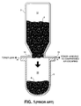
- FIGURE 1 Prior Art
- a simple dry toner refill bottle 2 is shown in a position to attempt to transfer toner 4 into a hard copy machine hopper 6 to add to the residual toner 8 from a prior filled condition.
- a dry toner refill system includes: a container for holding a refill charge of dry toner; a cap, affixed to said container, for selectively holding said dry toner charge within said container or selectively releasing said dry toner charge from said container into said storage hopper through said access for refilling said hopper; and a venting tube, connected to said cap, for allowing the displacement of air from said storage hopper into said container such that air displacement from said storage hopper into said container facilitates the transfer of dry toner from said container into said storage hopper.
- a dry toner refill bottle 102 or other suitable containment vessel, itself refillable with dry toner is provided.
- the bottle 102 can contain a charge of dry toner suitable to fill or partially fill a dry toner hopper of a hard copy apparatus.
- Provision of a refillable bottle 2 allows the machine operator to maintain a relatively large supply of dry toner at a location where a spill would not have any serious affects, such as an office store room, and so to be able to refill - arrow B - and cap the bottle safely.
- a cap assembly 104 includes a bottle 102 receiving sleeve portion 106.
- a bottle receiving sleeve portion 106 of the cap assembly 104 is adapted at one end 108 to fit over and snap fit in a substantially sealing manner over the bottle spout aperture 10.
- other connecting means such as mating screw threads on the cap and bottle spout can be equally or more effective than a snap fitment.
- the important feature is that the fit be tight enough to prevent leakage of dry toner at the interface between the bottle 102 and cap assembly 104 when engaged.
- the cap assembly 104 and the bottle 102 may be an integral unit with refill occurring through apertures 128 in the cap assembly as described hereinafter.
- a hopper mating mechanism 114 is provided.
- a hopper mounting member 116 is adapted to match the loading port of the particular hard copy machine with which the present invention is to be used. Referring briefly to FIGURE 3, an assemble version of the present invention is shown being connected to one hopper chamber access at hopper door 202. Obviously, many configurations of hopper chamber door shapes and sizes are possible and the mounting member designed accordingly.
- the hopper mounting member 116 is a plate 116 that can be simply implemented in a design expedient to mate accordingly with the machine hopper access in order to form a substantially air tight seal between the mounting plate 116 and the hopper chamber door 202.
- the hopper mounting plate 116 is provided with at least one slot 118 for mating with an alignment pin 204 (FIG. 3) at the hopper chamber door.
- the mounting plate 116 is provided with a protruding flange 122 that is designed to mate with a releasable securing clip 206 (FIG. 3) on the hard copy machine at the hopper access door 202.
- a cap spout mechanism 124 is affixed to the hopper mounting plate 116 such that when placed into position to transfer dry toner from the bottle 102 into the hopper toner chamber, the cap spout mechanism 124 fits in an adjacent or abutting relation with the chamber door 202.
- the cap spout mechanism 124 includes a first spout chamber portion 126 that further includes one or more nozzle apertures 128 in open communication with the bottle spout aperture 110.
- the nozzle apertures 110 surround a fixed air displacement tube 130.
- the air displacement tube 130 is designed such that when the cap assembly 104 is affixed to the bottle 102 the tube 130 extends from the cap spout mechanism 124 to the lower most region of the bottle containment chamber (see e.g., FIG. 5.).
- the cap spout mechanism 124 further includes a moveable door mechanism 132.
- a sliding door mechanism 132 is fit to the cap spout mechanism 124 by providing rails 134 to mate with a corresponding groove 136 on the cap spout mechanism 124.
- the size, shape and movement mechanism of the door is adaptable to many variations dependent on factors associated with the particular hard copy machine with which the refill system of the present invention is intended for use.
- the cap door mechanism 132 is further provided with a means for sealing 138 the first spout chamber portion 126 in order to prevent leakage of toner before the system is engaged with the hopper access.
- a sheet of Mylar (trademark) is provided to seal the nozzles 128 and the air displacement tube 130 when the cap door mechanism 132 is shut (that is pushed in the opposite direction to the arrow labeled "OPEN" in FIGURE 2).
- FIGURES 3,4 and 5 demonstrate the operation of the present invention.
- a hard copy machine 200 has one or more dry toner hoppers, for example one for each color toner used by the printing mechanism of the machine.
- the present invention is easily adaptable to various configurations of hopper doors 202.
- the machine 200 is shown to have hopper doors 202 which are manually opened by sliding a lever 208 in the direction of the arrow labeled "C.”
- a filled refill bottle 102 with the cap spout mechanism 114 in place and the cap door mechanism 132 closed is aligned with a machine hopper.
- the assembled dry toner refill system is fixed into mating position by engaging the alignment pin 204 of the hopper using the slot 118 of the mounting plate 116.
- the system is rotated in the direction of arrow "D" to engage the mounting plate flange 122 with the releasable securing clip 206.
- the refill system is "locked” into a substantially air tight sealing relationship with the hopper.
- the lever 208 is pushed to open the hopper door 202.
- pushing the lever 208 engages and simultaneously opens the hopper door 202 and pushes the cap door mechanism 132 to its "OPEN" position as previously shown in FIGURE 2.
- the mechanism may be as simple having the hopper door 202 "peal" the Mylar sheath as shown in FIGURE 5.
- dry toner 4 begins to fall -- as depicted by arrows labeled "F" -- into the hard copy machine's dry toner hopper containment chamber 14. As the powder falls, it displaces air in the chamber 14 from the chamber 14, through the air displacement tube 130, and into the interior of the dry toner bottle 102 as shown by arrows labelled "E.”
- the tube 130 is tapered from a wider diameter at the cap to a narrower diameter at the distal end. Air from the hopper chamber 14 is generally sufficient to dislodge any clog allowing it to blow into the container 102 or precipitate into the hopper chamber 14.
Abstract
In transferring dry toner from a dry toner refill container (102) to a storage hopper (14) in an electrophotographic machine (200), air displacement from the storage hopper into the refill container is used to facilitate the transfer of a refill charge (4) of dry toner from the refill container into the storage hopper. The system includes a cap apparatus (104) which permits refill of the container and substantially eliminates leakage of dry toner during the hopper refill process.
Description
- The present invention relates generally to electrophotographic technology, more particularly to dry toner electrophotographic hard copy apparatus, and, more specifically, to a system for refilling dry toner hoppers of such apparatus.
- Electrophotography is an electrostatic image-forming process in which an optical signal generator (e.g. light, such as a laser beam, or other energy forms, such as x-rays, or gamma rays) form an electrostatic image on a photoconductive insulating medium. Generally, the charge image areas attract and hold a "toner." The powder image is then transferred to a print medium, such as paper, or fused there by heat.
- One well-known example is the "xerographic" printing method in which a negative image is formed on an electrically charged plate then transferred and thermally fixed onto a paper as a positive. Computer laser printers also work using electrophotographic technology. Basic information regarding conventional techniques can be found in R.C.A. Vol. 15 (4), at p. 471 (1950) and IEEE Transactions on Electron Devices, Vol. Ed.-19, No. 4, pp. 396-412 (April 1972).
- "Dry toner" is a fine, resinous powder (generally black, but also now used in color printers and copiers) used in electrophotographic imaging processes to make an image readable. The toner is either deposited directly on a coated paper or transferred from a charged surface to ordinary paper, then fused to the paper by heating, such as thermocompression bonding.
- By its nature, the powdery toner is a difficult material to utilize. Dry toner has a tendency to agglomerate. If not properly handled, toner dust can settle within the apparatus and adversely affect component operation and overall apparatus performance.
- In operation, toner is expended as hard copies are generated by the electrophotographic apparatus. Therefore, electrophotographic machines generally require a refill. While replacement of a substantially sealed toner cartridge alleviates the necessity of handling loose toner, such cartridges are expensive. Therefore, refillable toner storage hoppers are often provided in the hard copy machine by the original equipment manufacturer.
- Referring to FIGURE 1 (Prior Art), a simple dry
toner refill bottle 2 is shown in a position to attempt to transfertoner 4 into a hardcopy machine hopper 6 to add to theresidual toner 8 from a prior filled condition. - As the
bottle 2 is inverted, and toner 4 shifts to block thenozzle 10 of thebottle 2, avacuum region 12 is formed in thebottle 2. At the same time, in the emptyvolume containment chamber 14 of thehopper 6 above theresidual toner 8 from a prior filling, the air starts to compress due to the exchange ofdry toner 4 from thebottle 2 into thehopper 6. Generally, the compressed air will leak at theinterface 16 of thebottle 2 and hopper 6 -- as depicted by arrows A -- and, due to the fine powdery nature of dry toner, result in an undesirable, spray-type "spill" of toner into the machine. - Such a spill of dry toner often requires service by a technician with expert knowledge. Besides the expense associated with service calls, there is added expense involved with the inability to use the machine while it is down, waiting for and receiving service.
- Therefore, there is a need for owners of such machines to be able to refill toner hoppers without expert knowledge and skill. As refilling the hopper from a toner refill package or bottle is inherently awkward and messy, there is a need for an improved hopper refill system.
- In its basic aspects, the present invention is useful for a hard copy apparatus, generally any type that includes a dry toner storage hopper, having a door providing an access for refilling said hopper. A dry toner refill system according to the present invention includes: a container for holding a refill charge of dry toner; a cap, affixed to said container, for selectively holding said dry toner charge within said container or selectively releasing said dry toner charge from said container into said storage hopper through said access for refilling said hopper; and a venting tube, connected to said cap, for allowing the displacement of air from said storage hopper into said container such that air displacement from said storage hopper into said container facilitates the transfer of dry toner from said container into said storage hopper.
- It is an advantage of the present invention that it substantially eliminates the possibility of a toner spill.
- It is another advantage of the present invention that it provides a free flow of toner from a refill container into an electrophotographic machine toner hopper.
- It is yet another advantage of the present invention to promote complete transfer of toner from a container into a receiving hopper without having to perform excessive tapping or shaking of the bottle to affect the transfer.
- Other objects, features and advantages of the present invention will become apparent upon consideration of the following detailed description and the accompanying drawings, in which like reference designations represent like features throughout the FIGURES.
-
- FIGURE 1 is a schematic drawing of the prior art.
- FIGURE 2 is schematic, perspective drawing of the present invention.
- FIGURE 3 is a schematic drawing of the present invention as shown in FIGURE 2 being attached to a hopper of a hard copy machine
- FIGURE 4 is a schematic drawing of the present invention as shown in FIGURE 3, connected to the hard copy machine.
- FIGURE 5 is a schematic, cross-sectional, plan view (side) depiction of the present invention as shown in FIGURE 2 in position to refill a hopper as shown in FIGURE 4.
- The drawings referred to in this description should be understood as not being drawn to scale except if specifically noted.
- Reference is made now in detail to a specific embodiment of the present invention, which illustrates the best mode presently contemplated by the inventor(s) for practicing the invention. Alternative embodiments are also briefly described as applicable.
- Referring to FIGURE 2, a dry
toner refill bottle 102, or other suitable containment vessel, itself refillable with dry toner is provided. Thebottle 102 can contain a charge of dry toner suitable to fill or partially fill a dry toner hopper of a hard copy apparatus. - Provision of a
refillable bottle 2 allows the machine operator to maintain a relatively large supply of dry toner at a location where a spill would not have any serious affects, such as an office store room, and so to be able to refill - arrow B - and cap the bottle safely. - A
cap assembly 104 includes abottle 102 receivingsleeve portion 106. A bottle receivingsleeve portion 106 of thecap assembly 104 is adapted at oneend 108 to fit over and snap fit in a substantially sealing manner over thebottle spout aperture 10. It will be recognized to a person-skilled-in-the-art other connecting means, such as mating screw threads on the cap and bottle spout can be equally or more effective than a snap fitment. The important feature is that the fit be tight enough to prevent leakage of dry toner at the interface between thebottle 102 andcap assembly 104 when engaged. Alternatively, thecap assembly 104 and thebottle 102 may be an integral unit with refill occurring throughapertures 128 in the cap assembly as described hereinafter. - At the
distal end 112 of thecap assembly 104 from thebottle fitment end 108 of thebottle 102, ahopper mating mechanism 114 is provided. - A
hopper mounting member 116 is adapted to match the loading port of the particular hard copy machine with which the present invention is to be used. Referring briefly to FIGURE 3, an assemble version of the present invention is shown being connected to one hopper chamber access athopper door 202. Obviously, many configurations of hopper chamber door shapes and sizes are possible and the mounting member designed accordingly. In the exemplary embodiment shown, thehopper mounting member 116 is aplate 116 that can be simply implemented in a design expedient to mate accordingly with the machine hopper access in order to form a substantially air tight seal between themounting plate 116 and thehopper chamber door 202. - Referring back to FIGURE 2, in the present embodiment, the
hopper mounting plate 116 is provided with at least oneslot 118 for mating with an alignment pin 204 (FIG. 3) at the hopper chamber door. At itsopposite end 120, themounting plate 116 is provided with aprotruding flange 122 that is designed to mate with a releasable securing clip 206 (FIG. 3) on the hard copy machine at thehopper access door 202. - A
cap spout mechanism 124 is affixed to thehopper mounting plate 116 such that when placed into position to transfer dry toner from thebottle 102 into the hopper toner chamber, thecap spout mechanism 124 fits in an adjacent or abutting relation with thechamber door 202. - The
cap spout mechanism 124 includes a firstspout chamber portion 126 that further includes one ormore nozzle apertures 128 in open communication with thebottle spout aperture 110. - The nozzle apertures 110 surround a fixed
air displacement tube 130. Theair displacement tube 130 is designed such that when thecap assembly 104 is affixed to thebottle 102 thetube 130 extends from thecap spout mechanism 124 to the lower most region of the bottle containment chamber (see e.g., FIG. 5.). - The
cap spout mechanism 124 further includes amoveable door mechanism 132. In the present embodiment of FIGURE 2, a slidingdoor mechanism 132 is fit to thecap spout mechanism 124 by providingrails 134 to mate with acorresponding groove 136 on thecap spout mechanism 124. Again, the size, shape and movement mechanism of the door is adaptable to many variations dependent on factors associated with the particular hard copy machine with which the refill system of the present invention is intended for use. - The
cap door mechanism 132 is further provided with a means for sealing 138 the firstspout chamber portion 126 in order to prevent leakage of toner before the system is engaged with the hopper access. In the present embodiment, a sheet of Mylar (trademark) is provided to seal thenozzles 128 and theair displacement tube 130 when thecap door mechanism 132 is shut (that is pushed in the opposite direction to the arrow labeled "OPEN" in FIGURE 2). - FIGURES 3,4 and 5 demonstrate the operation of the present invention.
- In FIGURE 3, a
hard copy machine 200 has one or more dry toner hoppers, for example one for each color toner used by the printing mechanism of the machine. Again, the present invention is easily adaptable to various configurations ofhopper doors 202. To exemplify the operation of the present invention, themachine 200 is shown to havehopper doors 202 which are manually opened by sliding alever 208 in the direction of the arrow labeled "C." - A filled
refill bottle 102 with thecap spout mechanism 114 in place and thecap door mechanism 132 closed is aligned with a machine hopper. With thehopper door 202 closed, the assembled dry toner refill system is fixed into mating position by engaging thealignment pin 204 of the hopper using theslot 118 of the mountingplate 116. The system is rotated in the direction of arrow "D" to engage the mountingplate flange 122 with the releasable securingclip 206. Thus, the refill system is "locked" into a substantially air tight sealing relationship with the hopper. - Referring now to FIGURE 4, the
lever 208 is pushed to open thehopper door 202. In the present embodiment, pushing thelever 208 engages and simultaneously opens thehopper door 202 and pushes thecap door mechanism 132 to its "OPEN" position as previously shown in FIGURE 2. The mechanism may be as simple having thehopper door 202 "peal" the Mylar sheath as shown in FIGURE 5. Alternative embodiments, such as leaf shutters, similarly should be configured to simultaneously open a correspondingly configured cap door mechanism. - Referring to FIGURE 5, once the hopper door and the
cap door mechanism 132 are in their respective OPEN positions,dry toner 4 begins to fall -- as depicted by arrows labeled "F" -- into the hard copy machine's dry tonerhopper containment chamber 14. As the powder falls, it displaces air in thechamber 14 from thechamber 14, through theair displacement tube 130, and into the interior of thedry toner bottle 102 as shown by arrows labelled "E." - Thus, the venting of air from the hopper into the bottle cavity relatively behind, that is, being vacated by, the dry toner refill charge promotes the flow from the bottle cavity into the
hopper chamber 14. - In order to prevent clogging of the
tube 130, in the preferred embodiment thetube 130 is tapered from a wider diameter at the cap to a narrower diameter at the distal end. Air from thehopper chamber 14 is generally sufficient to dislodge any clog allowing it to blow into thecontainer 102 or precipitate into thehopper chamber 14. - Once the
dry toner charge 4 has been transferred, the process steps are reversed. With the doors closed before removal of the refill system from the machine, the possibility of a dry toner spill has been virtually eliminated. - The foregoing description of the preferred embodiment of the present invention has been presented for purposes of illustration and description. It is not intended to be exhaustive or to limit the invention to the precise form disclosed. Obviously, many modifications and variations will be apparent to practitioners skilled in this art. Similarly, any process steps described might be interchangeable with other steps in order to achieve the same result. The embodiment was chosen and described in order to best explain the principles of the invention and its best mode practical application to thereby enable others skilled in the art to understand the invention for various embodiments and with various modifications as are suited to the particular use contemplated. It is intended that the scope of the invention be defined by the claims appended hereto and their equivalents.
Claims (10)
- In an hard copy apparatus (200), including a dry toner storage hopper (14), having a door (202) providing an access for refilling said hopper, a dry toner refill system comprising:
containing means (102) for holding a refill charge of dry toner (4);
capping means (104), affixed (106, 108) to said containing means, for selectively holding said dry toner charge within said containing means or selectively releasing said dry toner charge from said containing means into said storage hopper through said access for refilling said hopper; and
venting means (130), connected to said capping means, for allowing the displacement of air from said storage hopper into said containing means such that air displacement from said storage hopper into said containing means facilitates the transfer of dry toner from said containing means into said storage hopper. - The system as set forth in claim 1, wherein said capping means further comprising:
means (114) for substantially sealing said containing means to said storage hopper prior to selectively releasing said dry toner charge into said storage hopper. - The system as set forth in claim 1, wherein said capping means further comprises:
connecting means (114) for selectively connecting said containing means to said storage hopper in a substantially sealed configuration. - The device as set forth in claim 1, wherein said venting means further comprises:
an air displacement pipe (130) leading from said capping means at an end (110) of the containing means proximate said capping means into said containment means to an end of the containing means distal said capping means when said device is in position to transfer dry toner from said containing means into said storage hopper. - The system as set forth in claim 3, wherein said connecting means further comprises:
means for engaging said connecting means for opening said capping means to said door to selectively release said dry toner charge when said door is opened. - The system as set forth in claim 1, wherein said capping means is affixed to said containing means with a releasable engaging means for removing said capping means from said containing means for refilling said containing means.
- The system as set forth in claim 4, wherein said air displacement pipe is tapered from a wider diameter cross-section at said capping means end to a narrower diameter cross-section at a distal end thereof.
- A dry toner refill system for a electrophotographic hard copy machine, having a toner hopper with an access having door with a hopper accessing device for selectively closing said hopper or providing access to said hopper, said system comprising:
a containment vessel (102) adapted to hold a charge of toner in a cavity of said vessel for partially or completely refilling said hopper;
a capping assembly (114) for said containment vessel adapted to be affixed to said containment vessel, havinga. a sleeve portion (106) adapted to mate with said containment vessel in a substantially air tight seal;b. a mounting member (116) adapted to mate with said hopper access in a substantially air tight seal;c. a cap chamber portion (126) having at least one aperture (128) therethrough open to said cavity and adapted to allow said charge to be released from said cavity;d. an air displacement tube (130) adapted to allow air in said hopper to be vented into said cavity; ande. a movable cap sealing member (132) adapted to selectively seal and open said containment vessel;f. a means for connecting said movable cap sealing member to said hopper accessing device such that when said hopper accessing device is activated to allow access to said hopper said containment vessel cavity is substantially simultaneously opened to allow said charge to pass through said aperture. - The system as set forth in claim 9 wherein said means for connecting said movable cap sealing member to said hopper further comprises:
a Mylar sheathing means for being engaged with said hopper accessing device. - The system as set forth in claim 9, wherein said air displacement pipe is tapered from a wider diameter cross-section at said capping means end to a narrower diameter cross-section at a distal end thereof.
Applications Claiming Priority (2)
| Application Number | Priority Date | Filing Date | Title |
|---|---|---|---|
| US18074994A | 1994-01-12 | 1994-01-12 | |
| US180749 | 1994-01-12 |
Publications (1)
| Publication Number | Publication Date |
|---|---|
| EP0663628A1 true EP0663628A1 (en) | 1995-07-19 |
Family
ID=22661627
Family Applications (1)
| Application Number | Title | Priority Date | Filing Date |
|---|---|---|---|
| EP94113320A Withdrawn EP0663628A1 (en) | 1994-01-12 | 1994-08-25 | Dry toner refill system |
Country Status (2)
| Country | Link |
|---|---|
| EP (1) | EP0663628A1 (en) |
| JP (1) | JPH07219345A (en) |
Cited By (2)
| Publication number | Priority date | Publication date | Assignee | Title |
|---|---|---|---|---|
| EP1193569A3 (en) * | 2000-10-02 | 2004-09-08 | Xerox Corporation | Replaceable container assemblies for printers |
| DE102019006199B3 (en) * | 2019-09-03 | 2021-02-11 | BLOCKHELDEN GmbH | Dispensing device for hand-operated, dosed dispensing of powdery, hygroscopic material |
Families Citing this family (1)
| Publication number | Priority date | Publication date | Assignee | Title |
|---|---|---|---|---|
| JP6236741B2 (en) * | 2013-12-06 | 2017-11-29 | 株式会社リコー | Developer container and image forming apparatus |
Citations (4)
| Publication number | Priority date | Publication date | Assignee | Title |
|---|---|---|---|---|
| US4615364A (en) * | 1982-06-23 | 1986-10-07 | Konishiroku Photo Industry Co., Ltd. | Developer incoming device in electrostatic reproducing apparatus |
| JPH049982A (en) * | 1990-04-27 | 1992-01-14 | Mita Ind Co Ltd | Image forming device |
| JPH0588541A (en) * | 1991-09-28 | 1993-04-09 | Ricoh Co Ltd | Dry process developing device and handling method thereof |
| US5221945A (en) * | 1992-08-14 | 1993-06-22 | Xerox Corporation | Toner cartridge having an air passageway |
-
1994
- 1994-08-25 EP EP94113320A patent/EP0663628A1/en not_active Withdrawn
-
1995
- 1995-01-11 JP JP7018628A patent/JPH07219345A/en active Pending
Patent Citations (4)
| Publication number | Priority date | Publication date | Assignee | Title |
|---|---|---|---|---|
| US4615364A (en) * | 1982-06-23 | 1986-10-07 | Konishiroku Photo Industry Co., Ltd. | Developer incoming device in electrostatic reproducing apparatus |
| JPH049982A (en) * | 1990-04-27 | 1992-01-14 | Mita Ind Co Ltd | Image forming device |
| JPH0588541A (en) * | 1991-09-28 | 1993-04-09 | Ricoh Co Ltd | Dry process developing device and handling method thereof |
| US5221945A (en) * | 1992-08-14 | 1993-06-22 | Xerox Corporation | Toner cartridge having an air passageway |
Non-Patent Citations (2)
| Title |
|---|
| PATENT ABSTRACTS OF JAPAN vol. 016, no. 160 (P - 1340) 20 April 1992 (1992-04-20) * |
| PATENT ABSTRACTS OF JAPAN vol. 017, no. 432 (P - 1589) 10 August 1993 (1993-08-10) * |
Cited By (2)
| Publication number | Priority date | Publication date | Assignee | Title |
|---|---|---|---|---|
| EP1193569A3 (en) * | 2000-10-02 | 2004-09-08 | Xerox Corporation | Replaceable container assemblies for printers |
| DE102019006199B3 (en) * | 2019-09-03 | 2021-02-11 | BLOCKHELDEN GmbH | Dispensing device for hand-operated, dosed dispensing of powdery, hygroscopic material |
Also Published As
| Publication number | Publication date |
|---|---|
| JPH07219345A (en) | 1995-08-18 |
Similar Documents
| Publication | Publication Date | Title |
|---|---|---|
| EP0689104B1 (en) | Toner cartridge | |
| JP3347201B2 (en) | Developer container and image forming apparatus | |
| EP1542088B1 (en) | Toner powder storage container | |
| EP0853260B1 (en) | Developer cartridge and developer replenishing apparatus | |
| US7937018B2 (en) | Developer supply container | |
| KR100697127B1 (en) | Developer supply container | |
| US6751431B2 (en) | Developer replenishing device and developer container for use therewith | |
| US5812915A (en) | Press fit fill plugs with uniform sealing ability | |
| US6978107B2 (en) | Developer supply container | |
| US4912509A (en) | Integrated detachable image forming unit and developing unit of an image forming apparatus | |
| US20020164179A1 (en) | Toner replenishing device and image forming apparatus using the same | |
| GB2089689A (en) | Toner loading system | |
| CN112650034A (en) | Cartridge, replenishment container, and image forming apparatus | |
| CN100445889C (en) | Toner cartridge and mechanism of installing and removing the same | |
| US5475478A (en) | Developer unit and method of supplying developer | |
| EP0663628A1 (en) | Dry toner refill system | |
| US5970292A (en) | Securing feature for toner container shutter | |
| EP0555839B1 (en) | Apparatus for storing and dispensing pigmented marking particles | |
| EP0621515A2 (en) | Image forming apparatus having a photosensitive member | |
| US5970291A (en) | Self unlocking feature for toner container shutter | |
| JPH07199632A (en) | Developer container already filled with developer and developing device | |
| EP0248682A2 (en) | Image formation apparatus | |
| JP3347219B2 (en) | Image forming device | |
| JP2634082B2 (en) | hopper | |
| JP2004227017A (en) | Image developer supply device |
Legal Events
| Date | Code | Title | Description |
|---|---|---|---|
| PUAI | Public reference made under article 153(3) epc to a published international application that has entered the european phase |
Free format text: ORIGINAL CODE: 0009012 |
|
| AK | Designated contracting states |
Kind code of ref document: A1 Designated state(s): DE FR GB IT |
|
| STAA | Information on the status of an ep patent application or granted ep patent |
Free format text: STATUS: THE APPLICATION IS DEEMED TO BE WITHDRAWN |
|
| 18D | Application deemed to be withdrawn |
Effective date: 19960120 |