EP0663318A1 - Holder for beverage containers - Google Patents
Holder for beverage containers Download PDFInfo
- Publication number
- EP0663318A1 EP0663318A1 EP94119718A EP94119718A EP0663318A1 EP 0663318 A1 EP0663318 A1 EP 0663318A1 EP 94119718 A EP94119718 A EP 94119718A EP 94119718 A EP94119718 A EP 94119718A EP 0663318 A1 EP0663318 A1 EP 0663318A1
- Authority
- EP
- European Patent Office
- Prior art keywords
- holder according
- clamping part
- clamping
- lip
- holder
- Prior art date
- Legal status (The legal status is an assumption and is not a legal conclusion. Google has not performed a legal analysis and makes no representation as to the accuracy of the status listed.)
- Granted
Links
Images


Classifications
-
- B—PERFORMING OPERATIONS; TRANSPORTING
- B60—VEHICLES IN GENERAL
- B60N—SEATS SPECIALLY ADAPTED FOR VEHICLES; VEHICLE PASSENGER ACCOMMODATION NOT OTHERWISE PROVIDED FOR
- B60N3/00—Arrangements or adaptations of other passenger fittings, not otherwise provided for
- B60N3/10—Arrangements or adaptations of other passenger fittings, not otherwise provided for of receptacles for food or beverages, e.g. refrigerated
- B60N3/101—Arrangements or adaptations of other passenger fittings, not otherwise provided for of receptacles for food or beverages, e.g. refrigerated fixed
-
- B—PERFORMING OPERATIONS; TRANSPORTING
- B60—VEHICLES IN GENERAL
- B60N—SEATS SPECIALLY ADAPTED FOR VEHICLES; VEHICLE PASSENGER ACCOMMODATION NOT OTHERWISE PROVIDED FOR
- B60N3/00—Arrangements or adaptations of other passenger fittings, not otherwise provided for
- B60N3/10—Arrangements or adaptations of other passenger fittings, not otherwise provided for of receptacles for food or beverages, e.g. refrigerated
- B60N3/105—Arrangements or adaptations of other passenger fittings, not otherwise provided for of receptacles for food or beverages, e.g. refrigerated for receptables of different size or shape
- B60N3/108—Arrangements or adaptations of other passenger fittings, not otherwise provided for of receptacles for food or beverages, e.g. refrigerated for receptables of different size or shape with resilient holding elements
Definitions
- the innovation relates to a holder for liquid-filled containers to be carried along openly in a vehicle, such as cups, cans and the like in vehicles, consisting of a dimensionally stable carrier part, in particular a carrier part which is uniform in shape with an interior fitting part of the vehicle or with an interior fitting part which is form-fitably connected at least annular shape and at least one resiliently elastic clamping part directed transversely to the inside width of the carrier part, the clamping part having at least one retaining lip extending radially to the opening of the carrier part.
- a dimensionally stable carrier part in particular a carrier part which is uniform in shape with an interior fitting part of the vehicle or with an interior fitting part which is form-fitably connected at least annular shape and at least one resiliently elastic clamping part directed transversely to the inside width of the carrier part, the clamping part having at least one retaining lip extending radially to the opening of the carrier part.
- Holders for liquid-filled and in particular at least temporarily open containers to be carried in a vehicle are known in a large number of embodiments.
- a first and simplest type of holder of this type for containers filled with liquids and, in particular, at least temporarily open to be carried in a vehicle consists of a simple cup-shaped receiving part for a container and is essentially fraught with the disadvantage that only receptacles of one which is unchangeable by its opening width are afflicted in the receiving part Diameter can be used, since smaller containers can no longer be held stable or at least no longer rattle-free.
- Another type of such holder consists of a carrier part with a holding device arranged therein, in particular a type of tensioning strap for secure, stable and rattle-free fixing of containers, at least within more or less slight differences in diameter.
- this type of holder is only suitable for containers of the same diameter, it has the disadvantage that it requires considerable manufacturing effort is afflicted.
- U.S. Patent 4,530,480 In a further known type of holder for containers filled with liquid and in particular to be carried at least temporarily openly in a vehicle, a clamping part made of a foam material and provided with retaining lips directed radially to a receiving opening for a container to be inserted is inserted into a carrier part.
- a holder for liquid-filled and in particular at least temporarily open containers in vehicles to be carried in vehicles is known, the support part of which consists of two molded parts which complement one another to form a pot-shaped receiving part and in which a clamping part having radially inward-directed holding tongues is designed as a special plate-shaped component , which is set in the holder in connection with the mutual determination of the two parts of the cup-shaped receiving part.
- a design of the holder also allows a stable and sufficiently rattle-free mounting of containers of different diameters in vehicles, but due to the large number of its components it is also very expensive to manufacture and assemble.
- the innovation is based on the object of a holder of the type described at the beginning for liquid-filled and in particular at least temporarily open to be carried in a vehicle Form containers, such as cups, cans and the like. So that it can be produced on the one hand with the least possible effort and on the other hand for the safe and rattle-free holding of containers, such as cups, cans and the like Vehicle is suitable, and in addition a long, in particular the life of the vehicle corresponding operating time must be guaranteed. Furthermore, the holder to be created should be integrated or integrable into an already existing interior part of the vehicle.
- this object is essentially achieved in that the clamping part is designed as a two-component injection-molded part, at least in the region of its retaining lip, in such a way that the major part of its material thickness consists of a resiliently elastically deformable material with a rough surface and a thin-walled, im essential surface-forming part consists of a smooth sliding surface forming material.
- the design of the clamping part as a two-component injection molded part is initially characterized by the advantage of being easy to manufacture and, moreover, allows at least the retaining lip of the clamping part to be equipped with such a spring elasticity, which on the one hand ensures secure rattle-free holding of containers of different diameters and on the other
- a permanent clamping or holding force of the holding lips is ensured
- the surface-forming, thin-walled component also ensuring on the one hand a smooth surface which favors the insertion of a container and on the other hand largely ensures that the surface is free from wear.
- almost any holding characteristic of the holder can be set by appropriate choice of material or dimensioning of wall or layer thicknesses.
- a favorable form of realization is that the a portion of the wall thickness consisting of a resiliently elastically deformable plastic material makes up more than three-quarters of the total wall thickness of the retaining lip, an expedient material pair resulting, for example, from the fact that the resilient wall thickness part consists, for example, of TPE and the wall thickness part forming a smooth sliding surface consists, for example, of PP .
- the clamping part possibly also a clamping part formed exclusively by a holding lip, with which Carrier part can be locked in a form-fitting manner via mutually arranged projections and recesses.
- This design of the fastening of the clamping part on the carrier part allows above all the carrier part as a pot-like or trough-like recess in an interior part, for example, a shell-like plastic part, with a uniform design and the clamping part without great assembly effort and in particular without the use of a joint connection, such as gluing or welding , as well as permanently and sufficiently rigidly fixed in the carrier part without the aid of a tool.
- the clamping part has a shaft part which is at least partially identical in shape to the peripheral wall of the carrier part, the insertion of the clamping part into the carrier part on the one hand and the durability of the positive locking being optimized on the one hand by the fact that the Clamping part in the region of the free end of its shaft part is provided with radially outwardly projecting latching lugs and the carrier part is provided with complementarily designed and arranged latching recesses.
- the shaft part of the clamping part in the region of its free end, which carries one or more locking lugs is formed by means of axially directed, in particular slot-shaped, longitudinal recesses in the manner of spring tongues.
- the shaft part and the wall thickness part of the holding lip which consists of a plastic material forming a smooth sliding surface, are formed in one piece with the same shape and material. It can further be provided that the material thickness portion consisting of a smooth sliding surface plastic material is provided on the free edge of the retaining lip with a bead which engages over the end edge of the material thickness portion of the retaining lip consisting of a resilient plastic material.
- the carrier part is formed by a pot-shaped or trough-shaped recess in the interior trim part, which advantageously has a circular cross-sectional shape, but could also have any other cross-sectional shape.
- the shaft part of the clamping part extends only over a partial area of the inner circumference of the carrier part.
- the holding lip also extends only over a partial area of the opening width of the carrier part and expediently such that the holding lip of the clamping part has an approximately kidney-shaped shape in plan view, in that respect that at least in the central area of the free end edge of the retaining lip has an outward contour profile in the form of a circular arc.
- two clamping parts are preferably arranged opposite one another within the carrier part.
- clamping part designed in accordance with the innovation is in no way limited to use in conjunction with a carrier part which is of uniform shape with an interior fitting part, but rather is independent of the design and arrangement of the carrier part.
- An interior trim part 1 of a motor vehicle consists of a rigid, shell-shaped molded part made of a plastic material and is provided with a pot-shaped or trough-shaped depression 2 forming the support part, which is used for Recording of the container 3 to be carried in the vehicle, in the illustrated embodiment of a cup, is determined.
- the pot-shaped or trough-shaped depression 2 has a circular cross-sectional shape, however, could also have any other cross-sectional shape.
- two clamping parts 4 are inserted opposite one another in the depression 2 forming the carrier part.
- Each of the two clamping parts 4 extends only over part of the circumference of the depression 2 and consists of a shaft part 5 and a holding lip 6.
- the clamping part 4 is designed as a two-component injection-molded part, the retaining lip 6, viewed across its entire material thickness, made of a first material thickness part 7 made of a permanently resiliently elastic plastic material that forms a rough surface, for example TPE, and a second thin-walled material thickness part 8 consists of a plastic material forming a smooth sliding surface, for example PP.
- the thin-walled material thickness portion 8 of the holding lip 6 is formed with the shaft part 5 of the clamping part 4 in the same shape and material.
- the shaft part 5 of the clamping part 4 has a contour that is congruent with the inner circumference of the recess 2 and is provided at its free end with two locking lugs 9, to which corresponding complementary recesses 10 in the peripheral wall of the recess 2 are assigned.
- the shaft part 5 of the clamping part 4 is provided on both sides of each locking lug 9 with axially directed slot recesses 11 such that the locking lugs 9 are arranged on spring tongues 12, the shaft part 5 of the clamping part 4, as in particular from the Figure 4 can be seen, at least in the area of the spring tongues 12 is additionally provided with an inner bevel 13.
- the holding lip 6 of the clamping part 4 has an essentially kidney-shaped outline shape, such that both its outer and its inner contour form essentially circular arc sections.
- the portion of wall thickness 8 of the holding lip 6 formed by the plastic material forming a smooth sliding surface has a material thickness of only one sixth of the total wall thickness of the holding lip 6 and is provided with a bead 14 on the free edge of the holding lip 6. which overlaps the end edge of the material thickness portion 7 of the retaining lip 6, which is made of a resilient plastic material.
Abstract
Description
Die Neuerung bezieht sich auf einen Halter für flüssigkeitsbefüllte offen in einem Fahrzeug mitzuführende Behältnisse, wie Becher, Dosen und dergl. in Fahrzeugen, bestehend aus einem formstabilen Trägerteil, insbesondere einem mit einem Innenausstattungsteil des Fahrzeuges formeinheitlich bzw. zu einem Innenausstattungsteil formanschlußfähig ausgebideten Trägerteil, mit wenigstens ringförmiger Gestalt und mindestens einem quer zur lichten Weite des Trägerteiles gerichteten federnd elastischen Klemmteil , wobei das Klemmteil wenigstens eine sich radial zur Öffnung des Trägerteiles erstreckende Haltelippe aufweist.The innovation relates to a holder for liquid-filled containers to be carried along openly in a vehicle, such as cups, cans and the like in vehicles, consisting of a dimensionally stable carrier part, in particular a carrier part which is uniform in shape with an interior fitting part of the vehicle or with an interior fitting part which is form-fitably connected at least annular shape and at least one resiliently elastic clamping part directed transversely to the inside width of the carrier part, the clamping part having at least one retaining lip extending radially to the opening of the carrier part.
Halter für flüssigkeitsbefüllte und insbesondere wenigstens vorrübergehend offen in einem Fahrzeug mitzuführende Behältnisse, wie Becher, Dosen und dergl. sind in einer Vielzahl vom Ausführungsformen bekannt.
Eine erste und einfachste Bauart solcher Halter für flüssigkeitsbefüllte und insbesondere wenigstens vorrübergehend offen in einem Fahrzeug mitzuführende Behältnisse, besteht aus einem einfachen topfförmigen Aufnahmeteil für einen Behältnisse und ist im Wesentlichen mit dem Nachteil behaftet, daß in das Aufnahmeteil nur Behältnisse eines durch dessen Öffnungsweite unveränderlich vorgegebenen Durchmessers einsetzbar sind, da kleinere Behältnisse nicht mehr standsicher oder zumindest nicht mehr klapperfrei gehalten werden können.
Eine andere Bauart solcher Halter besteht aus einem Trägerteil mit einer darin angeordneten Halteeinrichtung, insbesondere eine Art Spannband zur sicheren standfesten und klapperfreien Festlegung von Behältnissen, wenigstens innerhalb mehr oder minder geringfügiger Durchmesserunterschiede. Diese Bauart von Haltern weist neben dem Nachteil, daß sie auch nur für Behältnisse eingerigermaßen gleichen Durchmessers geeignet ist vor allem den Nachteil auf, daß sie mit einem erhebblichen Herstellungsaufwand behaftet ist. (US-PS 4 530 480)
Bei einer weiteren bekannten Bauart von Haltern für flüssigkeitsbefüllte und insbesondere wenigstens vorrübergehend offen in einem Fahrzeug mitzuführende Behältnisse ist in ein Trägerteil ein aus einem Schaumstoffmaterial hergestelltes und mit radial zu einer Aufnahmeöffnung für einen einzusetzenden Behältnisse gerichteten Haltelippen versehenes Klemmteil eingesetzt. Diese Bauart von Haltern für Behältnisse ist auf Grund der weitgehenden elastischen Verformbarkeit des Schaumstoffmaterials an sich und vor allem auf Grund der Ausbildung radial zur Aufnahmeöffnung gerichteter Haltelippen zwar hinreichend geeignet Behältnisse unterschiedlicher Durchmesser aufzunehmen und auch standsicher und klapperfrei zu haltern, jedoch bringt die Verwendung von Schaumstoffmaterial als Klemmteil den Nachteil einer umständlichen Zusammenbaues und ferner der Gefahr einer vorzeitigen Materialabnutzung-und Ermüdung mit sich. (DE-Gbm 84 23 158.029)Holders for liquid-filled and in particular at least temporarily open containers to be carried in a vehicle, such as cups, cans and the like, are known in a large number of embodiments.
A first and simplest type of holder of this type for containers filled with liquids and, in particular, at least temporarily open to be carried in a vehicle, consists of a simple cup-shaped receiving part for a container and is essentially fraught with the disadvantage that only receptacles of one which is unchangeable by its opening width are afflicted in the receiving part Diameter can be used, since smaller containers can no longer be held stable or at least no longer rattle-free.
Another type of such holder consists of a carrier part with a holding device arranged therein, in particular a type of tensioning strap for secure, stable and rattle-free fixing of containers, at least within more or less slight differences in diameter. In addition to the disadvantage that this type of holder is only suitable for containers of the same diameter, it has the disadvantage that it requires considerable manufacturing effort is afflicted. (U.S. Patent 4,530,480)
In a further known type of holder for containers filled with liquid and in particular to be carried at least temporarily openly in a vehicle, a clamping part made of a foam material and provided with retaining lips directed radially to a receiving opening for a container to be inserted is inserted into a carrier part. This type of holder for containers is due to the extensive elastic deformability of the foam material itself and especially due to the design of radially directed holding lips directed to the receiving opening, suitable to hold containers of different diameters and also to hold them securely and without rattling, but the use of foam material does as a clamping part the disadvantage of cumbersome assembly and furthermore the risk of premature material wear and fatigue. (DE-Gbm 84 23 158.029)
Schließlich ist noch ein Halter für flüssigkeitsbefüllte und insbesondere wenigstens vorrübergehend offen in einem Fahrzeug mitzuführende Behältnisse in Fahrzeugen bekannt, dessen Trägerteil aus zwei einander zu einem topfförmigen Aufnahmeteil ergänzenden Formteilen besteht und bei dem ein radial nach innen gerichtete Haltezungen aufweisendes Klemmteil als besonderes plattenförmiges Bauteil ausgebildet ist, welches im Halter im Zusammenhang mit der gegenseitigen Festlegung der beiden Teile des topfförmigen Aufnahmeteiles festgelegt wird. Eine derartige Ausbildung des Halters gestattet zwar gleichfalls eine standsichere und hinreichend klapperfreie Halterung von Behältnissen unterschiedlicher Durchmesser in Fahrzeugen, ist jedoch infolge der Vielzahl seiner Bestandteile gleichfalls auch mit einem sehr hohen Herstellungs-und Montageaufwand behaftet. (US-PS 4 818 017)Finally, a holder for liquid-filled and in particular at least temporarily open containers in vehicles to be carried in vehicles is known, the support part of which consists of two molded parts which complement one another to form a pot-shaped receiving part and in which a clamping part having radially inward-directed holding tongues is designed as a special plate-shaped component , which is set in the holder in connection with the mutual determination of the two parts of the cup-shaped receiving part. Such a design of the holder also allows a stable and sufficiently rattle-free mounting of containers of different diameters in vehicles, but due to the large number of its components it is also very expensive to manufacture and assemble. (U.S. Patent 4,818,017)
Der Neuerung liegt die Aufgabe zugrunde einen Halter der eingangs bezeichneten Art für flüssigkeitsbefüllte und insbesondere wenigstens vorrübergehend offen in einem Fahrzeug mitzuführende Behältnisse, wie Becher, Dosen und dergl. so auszubilden, daß er auf der einen Seite mit einem geringstmöglichen Aufwand herstellbar ist und auf der anderen Seite zur sicheren und klapperfreien Halterung von Behältnissen, wie Bechern, Dosen und dergl. unterschiedlichster Durchmesser auch in einem fahrenden Fahrzeug geeignet ist, und wobei zudem eine lange, insbesondere der Lebensdauer des Fahrzeuges entsprechende Betriebszeit gewährleistet sein muß. Ferner soll der zu schaffende Halter in ein ohnehin vorhandenes Innenausstattungsteil des Fahrzeuges integriert oder integrierbar sein.The innovation is based on the object of a holder of the type described at the beginning for liquid-filled and in particular at least temporarily open to be carried in a vehicle Form containers, such as cups, cans and the like. So that it can be produced on the one hand with the least possible effort and on the other hand for the safe and rattle-free holding of containers, such as cups, cans and the like Vehicle is suitable, and in addition a long, in particular the life of the vehicle corresponding operating time must be guaranteed. Furthermore, the holder to be created should be integrated or integrable into an already existing interior part of the vehicle.
Diese Aufgabe wird neuerungsgemäß im Wesentlichen dadurch gelöst, daß das Klemmteil zumindest im Bereich seiner Haltelippe als Zwei-Komponenten-Spritzgußteil ausgebildet ist, in der Weise, daß der überwiegende Teil seiner Materialdicke aus einem federnd elastisch verformbaren Material mit rauher Oberfläche und einem dünnwandigen, im wesentlichen oberflächenbildenden Teil aus einem glatte Gleitflächen bildenden Material besteht.According to the innovation, this object is essentially achieved in that the clamping part is designed as a two-component injection-molded part, at least in the region of its retaining lip, in such a way that the major part of its material thickness consists of a resiliently elastically deformable material with a rough surface and a thin-walled, im essential surface-forming part consists of a smooth sliding surface forming material.
Die Ausbildung des Klemmteiles als Zwei-Komponenten-Spritzgußteil zeichnet sich zunächst durch den Vorteil einer einfachen Herstellbarkeit aus und gestattet darüberhinaus wenigstens die Haltelippe des Klemmteiles mit einer solchen Federelastizität auszustatten, die auf der einen Seite ein sicheres klapperfreies Festhalten von Behältnissen unterschiedlichster Durchmesser und auf der anderen Seite eine bleibende Spann- bzw. Haltekraft der Haltelippen gewährleistet, wobei zudem die oberflächenbildende, dünnwandig ausgebildete Komponente zum einen eine glatte, das Einsetzen eines Behältnisses begünstigende Oberfläche und zum anderen eine weitgehende Abnutzungsfreiheit der Oberfläche gewährleistet. Darüberhinaus kann, ohne die vorgenannten Vorteile aufgeben zu müssen, durch entsprechende Materialwahl oder Bemessung von Wandungs- bzw. Schichtdicken nahezu jedes beliebige Haltecharakteristik des Halters eingestellt werden.The design of the clamping part as a two-component injection molded part is initially characterized by the advantage of being easy to manufacture and, moreover, allows at least the retaining lip of the clamping part to be equipped with such a spring elasticity, which on the one hand ensures secure rattle-free holding of containers of different diameters and on the other On the other hand, a permanent clamping or holding force of the holding lips is ensured, the surface-forming, thin-walled component also ensuring on the one hand a smooth surface which favors the insertion of a container and on the other hand largely ensures that the surface is free from wear. Furthermore, without having to give up the advantages mentioned above, almost any holding characteristic of the holder can be set by appropriate choice of material or dimensioning of wall or layer thicknesses.
Eine günstige Verwirklichungsform besteht dabei darin, daß der aus einem federnd elastisch verfortmbaren Kunststoffmaterial bestehende Anteil der Wandungsdicke mehr als drei-viertel der gesamten Wandungsdicke der Haltelippe ausmacht, wobei sich eine zweckmäßige Materialpaarung beispielsweise daraus ergibt, daß der federnd elastische Wandungsdickenteil beispielsweise aus TPE und der eine glatte Gleitfläche bildende Wandungsdickenteil beispielsweise aus PP besteht.A favorable form of realization is that the a portion of the wall thickness consisting of a resiliently elastically deformable plastic material makes up more than three-quarters of the total wall thickness of the retaining lip, an expedient material pair resulting, for example, from the fact that the resilient wall thickness part consists, for example, of TPE and the wall thickness part forming a smooth sliding surface consists, for example, of PP .
Im Interesse einer leichten Herstellbarkeit und vor allem der Möglichkeit den Halter in ein ohnehin vorhandenes, insbesondere als Formteil aus einem Kunststoffmaterial ausgebildetes Innenausstattungsteil des Fahrzeuges integrieren zu können ist vorteilhafterweise vorgesehen, daß das Klemmteil, gegebenenfalls auch ein ausschließlich durch eine Haltelippe gebildetes Klemmteil, mit dem Trägerteil über wechselseitig angeordnete Vorsprünge und Ausnehmungen formschlüssig verrastbar ist. Diese Ausbildung der Befestigung des Klemmteiles am Trägerteil gestattet es vor allem das Trägerteil als topf-oder trogartige Vertiefung in einem, z.b: als schalenartiges Kunststoffteil ausgebildeten Innenausstattungsteil formeinheitlich ausbilden und das Klemmteil ohne großen Montageaufwand und insbesondere ohne die Anwendung einer Fügeverbindung, wie Klebung oder Schweißung, sowie ohne Zuhilfenahme eines Werkzeuges dauerhaft und hinreichend starr im Trägerteil festzulegen.In the interest of ease of manufacture and above all the possibility of being able to integrate the holder into an already existing interior part of the vehicle, in particular as a molded part made of a plastic material, it is advantageously provided that the clamping part, possibly also a clamping part formed exclusively by a holding lip, with which Carrier part can be locked in a form-fitting manner via mutually arranged projections and recesses. This design of the fastening of the clamping part on the carrier part allows above all the carrier part as a pot-like or trough-like recess in an interior part, for example, a shell-like plastic part, with a uniform design and the clamping part without great assembly effort and in particular without the use of a joint connection, such as gluing or welding , as well as permanently and sufficiently rigidly fixed in the carrier part without the aid of a tool.
Eine besonders vorteilfte Ausgestaltung wird in diesem Zusammenhang darin gesehen, daß das Klemmteil einen wenigstens abschnittsweise formgleich zur Umfangswandung des Trägerteiles ausgebildeten Schaftteil aufweist, wobei zum einen das Einsetzen des Klemmteiles in das Trägerteil und zum anderen die Haltbarkeit der formschlüssigen Verrastung dadurch optimiert werden, daß das Klemmteil im Bereich des freien Endes seines Schaftteiles mit radial nach außen vorspringenden Rastnasen und das Trägerteil mit komplementär ausgebildeten und angeordneten Rastausnehmungen versehen ist. Insbesondere erscheint es hierbei vorteilhaft, daß das Schaftteil des Klemmteiles im Bereich seines freien, die eine oder mehrere Rastnasen tragenden Endes vermittels axial gerichteter insbesondere schlitzförmiger Längsausnehmungen federzungenartig ausgebildet ist. In diesem Zusammenhang ist zweckmäßigerweise ferner vorgesehen, daß das Schaftteil und der aus einem eine glatte Gleitfläche bildenden Kunststoffmaterial bestehende Wandungsdickenteil der Haltelippe form-und materialeinheitlich einteilig ausgebildet sind. Hierbei kann weiter vorgesehen sein, daß der aus einem eine glatte Gleitfläche bildenden Kunststoffmaterial bestehende Materialdickenanteil am freien Rand der Haltelippe mit einem Wulst versehen ist, welcher den Stirnrand des aus einem federnd elastischen Kunststoffmaterial bestehenden Materialdickenanteiles der Haltelippe übergreift.A particularly advantageous embodiment in this context is seen in the fact that the clamping part has a shaft part which is at least partially identical in shape to the peripheral wall of the carrier part, the insertion of the clamping part into the carrier part on the one hand and the durability of the positive locking being optimized on the one hand by the fact that the Clamping part in the region of the free end of its shaft part is provided with radially outwardly projecting latching lugs and the carrier part is provided with complementarily designed and arranged latching recesses. In particular, it appears advantageous here that the shaft part of the clamping part in the region of its free end, which carries one or more locking lugs is formed by means of axially directed, in particular slot-shaped, longitudinal recesses in the manner of spring tongues. In this connection, it is also expediently provided that the shaft part and the wall thickness part of the holding lip, which consists of a plastic material forming a smooth sliding surface, are formed in one piece with the same shape and material. It can further be provided that the material thickness portion consisting of a smooth sliding surface plastic material is provided on the free edge of the retaining lip with a bead which engages over the end edge of the material thickness portion of the retaining lip consisting of a resilient plastic material.
Das Trägerteil ist durch eine topf-oder trogförmige Vertiefung im Innenausstattungsteil gebildet, welche vorteilhafterweise eine kreisrunde Querschnittsform aufweist, jedoch auch jede beliebige andere Querschnittsform aufweisen könnte.The carrier part is formed by a pot-shaped or trough-shaped recess in the interior trim part, which advantageously has a circular cross-sectional shape, but could also have any other cross-sectional shape.
In weiterer zweckmäßiger Einzelausgestaltung ist dann weiter vorgesehen, daß das Schaftteil des Klemmteiles sich lediglich über einen Teilbereich des Innenunfanges des Trägerteiles hin erstreckt. Hand in Hand mit einer solchen Ausbildung des Schaftteiles des Klemmteiles ist weiterhin auch vorgesehen, daß sich auch die Haltelippe lediglich über einen Teilbereich der Öffnungsweite des Trägerteiles hin erstreckt und zwar zweckmäßigerweise derart, die Haltelippe des Klemmteiles in der Draufsicht eine etwa nierenförmige Gestalt besitzt, dahingehend, daß mindestens in deren mittleren Bereich der freie Stirnrand der Haltelippe einen kreisbogenartig nach außen gerichteten Konturverlauf aufweist.In a further expedient individual configuration, it is further provided that the shaft part of the clamping part extends only over a partial area of the inner circumference of the carrier part. Hand in hand with such a design of the shaft part of the clamping part, it is also provided that the holding lip also extends only over a partial area of the opening width of the carrier part and expediently such that the holding lip of the clamping part has an approximately kidney-shaped shape in plan view, in that respect that at least in the central area of the free end edge of the retaining lip has an outward contour profile in the form of a circular arc.
Zwar kann für einen, vor allem hinsichtlich der Durchmesser der in den Halter einsetzbaren Behältnisse begrenzten, Anwendungsbereich die Anordnung lediglich eines Klemmteiles innerhalb des Trägerteiles vorgesehen und auch ausreichend sein, bevorzugterweise sind aber innerhalb des Trägerteiles zwei Klemmteile einander gegenüberliegend angeordnet.Although the arrangement of only one clamping part within the carrier part can be provided and also sufficient for an application area, which is limited especially with regard to the diameter of the containers that can be inserted into the holder, two clamping parts are preferably arranged opposite one another within the carrier part.
Die Anwendung eines neuerungsgemäß gestalteten Klemmteiles ist keineswegs nur auf die Verwendung in Verbindung mit mit einem Innenausstattungsteil formeinheitlich ausgebildeten Trägerteil beschränkt, sondern vielmehr von der Ausbildung und Anordnung des Trägerteiles unabhängig.The use of a clamping part designed in accordance with the innovation is in no way limited to use in conjunction with a carrier part which is of uniform shape with an interior fitting part, but rather is independent of the design and arrangement of the carrier part.
Die Neuerung ist nachfolgend anhand eines in der Zeichnung dargestellten Ausführungsbeispieles im Einzelnen beschrieben. In der Zeichnung zeigt die
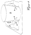
- Figur 1
- eine schaubildliche Darstellung eines neuerungsgemäßen Halters für Behältnisse;
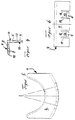
- Figur 2
- eine Draufsicht auf die Einbaulage von Haltern in einem Fahrzeug;
Figur 3- einen Längsschnitt durch ein mit einem Halter für Behältnisse ausgestattetes Innenausstattungsteil;
Figur 4- einen Teilschnitt durch das Klemmteil des Halters;
Figur 5- eine Draufsicht auf das Klemmteil des Halters gemäß
Figur 4; - Figur 6
- eine Stirnansicht des des Klemmteiles des Halters nach
Figur 4 und 5;
- Figure 1
- a diagrammatic representation of an inventive holder for containers;
- Figure 2
- a plan view of the mounting position of holders in a vehicle;
- Figure 3
- a longitudinal section through an interior fitting equipped with a holder for containers;
- Figure 4
- a partial section through the clamping part of the holder;
- Figure 5
- a plan view of the clamping part of the holder according to Figure 4;
- Figure 6
- an end view of the clamping part of the holder according to Figures 4 and 5;
Ein in der Figur 2 nur teilweise dargestelltes Innenausstattungsteil 1 eines Kraftfahrzeuges, wie Mittelkonsole M oder Armlehne oder dergl., besteht aus einem starren, schalenartig ausgebildeten Formteil aus einem Kunststoffmaterial und ist mit einer das Trägerteil bildenden topf-oder trogförmigen Vertiefung 2 versehen, welche zur Aufnahme des im Fahrzeug mitzuführenden Behältnisses 3, im gezeigten Ausführungsbeispiel eines Bechers, bestimmt ist. Im Ausführungsbeispiel besitzt die topf-oder trogförmige Vertiefung 2 eine kreisrunde Querschnittsform, könnte jedoch auch jede beliebige andere Querschnittsform aufweisen. In die das Trägerteil bildende Vertiefung 2 sind im gezeigten Ausführungsbeispiel zwei Klemmteile 4 einander gegenüberliegend eingesetzt. Jedes der beiden Klemmteile 4 erstreckt sich lediglich über einen Teil des Umfanges der Vertiefung 2 hin und besteht aus einem Schaftteil 5 und einer Haltelippe 6.
Das Klemmteil 4 ist als Zwei-Komponenten-Spritzgußteil ausgeführt, wobei die Haltelippe 6, über ihre gesamte Materialdicke hin gesehen, aus einem ersten Materialdickenteil 7 aus einem bleibend federnd elastischen, eine rauhe Oberfläche bildenden Kunststoffmaterial, beispielsweise TPE, und einem zweiten dünnwandigen Materialdickenteil 8 aus einem eine glatte Gleitfläche bildenden Kunststoffmaterial, beispielsweise PP, besteht. Der dünnwandige Materialdickkenanteil 8 der Haltelippe 6 ist mit dem Schaftteil 5 des Klemmteiles 4 form-und materialeinheitlich ausgebildet.
Der Schaftteil 5 des Klemmteiles 4 weist einen zum Innenumfang der Vertiefung 2 deckungsgleichen Konturverlauf auf und ist an seinem freien Ende mit zwei Rastnasen 9 versehen, welchen entsprechende komplementär ausgebildete Rastausnehmungen 10 in der Umfangswandung der Vertiefung 2 zugeordnet sind. Wie insbesondere aus der Figur 4 ersichtlich, ist der Schaftteil 5 des Klemmteiles 4 beiderseits jeder Rastnase 9 mit axial gerichteten Schlitzausnehmungen 11 versehen, derart, daß die Rastnasen 9 an Federzungen 12 angeordnet sind, wobei der Schaftteil 5 des Klemmteiles 4, wie insbesondere aus der Figur 4 ersichtlich, wenigstens im Bereich der Federzungen 12 zusätzlich noch mit einer innenseitigen Abschrägung 13 versehen ist. In der Draufsicht weist die Haltelippe 6 des Klemmteiles 4 eine im Wesentlichen nierenförmige Grundrißform auf, derart, daß sowohl ihr äußerer als auch ihr innerer Konturverlauf im wesentlichen Kreisbogenabschnitte bilden. Wie insbesondere aus der Figur 4 weiterhin ersichtlich besitzt der durch das eine glatte Gleitfläche bildende Kunststoffmaterial gebildete Wandungsdickenanteil 8 der Haltelippe 6 eine Materialstärke von lediglich einem Sechstel der gesamten Wandungsdicke der Haltelippe 6 und ist am freien Rand der Haltelippe 6 mit einem Wulst 14 versehen, welcher den Stirnrand des aus einem federnd elastischen Kunststoffmaterial bestehenden Materialdickenanteiles 7 der Haltelippe 6 übergreift.An interior trim part 1 of a motor vehicle, only partially shown in FIG. 2, such as center console M or armrest or the like, consists of a rigid, shell-shaped molded part made of a plastic material and is provided with a pot-shaped or trough-shaped depression 2 forming the support part, which is used for Recording of the
The
The
Claims (13)
Applications Claiming Priority (2)
| Application Number | Priority Date | Filing Date | Title |
|---|---|---|---|
| DE9400061U | 1994-01-04 | ||
| DE9400061U DE9400061U1 (en) | 1993-12-09 | 1994-01-04 | Holder for liquid-filled containers to be carried openly in a vehicle, such as cups, cans and the like. |
Publications (2)
| Publication Number | Publication Date |
|---|---|
| EP0663318A1 true EP0663318A1 (en) | 1995-07-19 |
| EP0663318B1 EP0663318B1 (en) | 1998-03-18 |
Family
ID=6902815
Family Applications (1)
| Application Number | Title | Priority Date | Filing Date |
|---|---|---|---|
| EP19940119718 Expired - Lifetime EP0663318B1 (en) | 1994-01-04 | 1994-12-14 | Holder for beverage containers |
Country Status (1)
| Country | Link |
|---|---|
| EP (1) | EP0663318B1 (en) |
Cited By (9)
| Publication number | Priority date | Publication date | Assignee | Title |
|---|---|---|---|---|
| WO1999014075A1 (en) * | 1997-09-12 | 1999-03-25 | Volkswagen Aktiengesellschaft | Holding device for a motor vehicle container |
| EP1074428A2 (en) | 1999-08-05 | 2001-02-07 | Volkswagen Aktiengesellschaft | Support for a beverage container for automotive vehicles |
| DE19961174A1 (en) * | 1999-12-17 | 2001-06-28 | Volkswagen Ag | Holder for drink cans and bottles in vehicle, with frame at side, and including storage element on which container can be stored sideways |
| EP1291238A3 (en) * | 2001-09-06 | 2004-01-02 | fischer automotive systems GmbH | Champagne glass holder |
| EP1258391A3 (en) * | 2001-05-16 | 2004-01-28 | Fischerwerke Arthur Fischer GmbH & Co. KG | Beverage holder for a shaped bottle |
| EP1410946A1 (en) * | 2002-10-15 | 2004-04-21 | Ford Global Technologies, Inc. | Cupholder |
| EP1431114A3 (en) * | 2002-12-18 | 2005-06-15 | fischer automotive systems GmbH | Holder for beverage containers |
| DE19802897B4 (en) * | 1997-01-28 | 2008-08-21 | Suzuki Motor Corp., Hamamatsu | Cup holder device |
| RU2681384C2 (en) * | 2015-12-16 | 2019-03-06 | ФОРД ГЛОУБАЛ ТЕКНОЛОДЖИЗ, ЭлЭлСи | Self-adjusting cup holder |
Families Citing this family (3)
| Publication number | Priority date | Publication date | Assignee | Title |
|---|---|---|---|---|
| DE19937339B4 (en) * | 1999-08-11 | 2008-10-30 | Audi Ag | container holder |
| DE19959991C2 (en) * | 1999-12-13 | 2001-10-18 | Audi Ag | Container holder |
| DE102011008581B4 (en) * | 2011-01-14 | 2019-11-28 | Audi Ag | Container holder for a vehicle interior of a vehicle for holding beverage containers |
Citations (7)
| Publication number | Priority date | Publication date | Assignee | Title |
|---|---|---|---|---|
| US2215411A (en) * | 1939-08-08 | 1940-09-17 | Sebring Floyd | Bottle holder |
| US2584646A (en) * | 1949-10-21 | 1952-02-05 | James A Wagstaff | Combined automobile tray and receptacle-supporting device |
| DE2700107A1 (en) * | 1977-01-04 | 1978-07-13 | Heinz Fischer | Bottle container for motor vehicles - consists of a housing made from plastic foam with openings in the top to hold bottles |
| US4852843A (en) * | 1988-09-07 | 1989-08-01 | Chandler Daniel E | Beverage holder for attachment to vehicle heating and cooling vents |
| WO1991011945A1 (en) * | 1990-02-14 | 1991-08-22 | Michael Peter Shields | Container support device |
| US5087008A (en) * | 1989-07-14 | 1992-02-11 | Prince Corporation | Multiple container holder |
| DE4224701A1 (en) * | 1992-07-25 | 1994-01-27 | Euwe Eugen Wexler Gmbh | Holder for drink container for use in vehicle - has circular gripping section with inwardly projecting deflectable flaps having radial extension of 20-30 per cent of inner holder radius |
-
1994
- 1994-12-14 EP EP19940119718 patent/EP0663318B1/en not_active Expired - Lifetime
Patent Citations (7)
| Publication number | Priority date | Publication date | Assignee | Title |
|---|---|---|---|---|
| US2215411A (en) * | 1939-08-08 | 1940-09-17 | Sebring Floyd | Bottle holder |
| US2584646A (en) * | 1949-10-21 | 1952-02-05 | James A Wagstaff | Combined automobile tray and receptacle-supporting device |
| DE2700107A1 (en) * | 1977-01-04 | 1978-07-13 | Heinz Fischer | Bottle container for motor vehicles - consists of a housing made from plastic foam with openings in the top to hold bottles |
| US4852843A (en) * | 1988-09-07 | 1989-08-01 | Chandler Daniel E | Beverage holder for attachment to vehicle heating and cooling vents |
| US5087008A (en) * | 1989-07-14 | 1992-02-11 | Prince Corporation | Multiple container holder |
| WO1991011945A1 (en) * | 1990-02-14 | 1991-08-22 | Michael Peter Shields | Container support device |
| DE4224701A1 (en) * | 1992-07-25 | 1994-01-27 | Euwe Eugen Wexler Gmbh | Holder for drink container for use in vehicle - has circular gripping section with inwardly projecting deflectable flaps having radial extension of 20-30 per cent of inner holder radius |
Cited By (12)
| Publication number | Priority date | Publication date | Assignee | Title |
|---|---|---|---|---|
| DE19802897B4 (en) * | 1997-01-28 | 2008-08-21 | Suzuki Motor Corp., Hamamatsu | Cup holder device |
| WO1999014075A1 (en) * | 1997-09-12 | 1999-03-25 | Volkswagen Aktiengesellschaft | Holding device for a motor vehicle container |
| BE1012293A3 (en) * | 1997-09-12 | 2000-09-05 | Volkswagen Ag | Confirmation of a recipient in a motor vehicle. |
| EP1074428A2 (en) | 1999-08-05 | 2001-02-07 | Volkswagen Aktiengesellschaft | Support for a beverage container for automotive vehicles |
| EP1074428A3 (en) * | 1999-08-05 | 2002-08-07 | Volkswagen Aktiengesellschaft | Support for a beverage container for automotive vehicles |
| DE19961174A1 (en) * | 1999-12-17 | 2001-06-28 | Volkswagen Ag | Holder for drink cans and bottles in vehicle, with frame at side, and including storage element on which container can be stored sideways |
| DE19961174B4 (en) * | 1999-12-17 | 2010-11-25 | Volkswagen Ag | Holder for a liquid container |
| EP1258391A3 (en) * | 2001-05-16 | 2004-01-28 | Fischerwerke Arthur Fischer GmbH & Co. KG | Beverage holder for a shaped bottle |
| EP1291238A3 (en) * | 2001-09-06 | 2004-01-02 | fischer automotive systems GmbH | Champagne glass holder |
| EP1410946A1 (en) * | 2002-10-15 | 2004-04-21 | Ford Global Technologies, Inc. | Cupholder |
| EP1431114A3 (en) * | 2002-12-18 | 2005-06-15 | fischer automotive systems GmbH | Holder for beverage containers |
| RU2681384C2 (en) * | 2015-12-16 | 2019-03-06 | ФОРД ГЛОУБАЛ ТЕКНОЛОДЖИЗ, ЭлЭлСи | Self-adjusting cup holder |
Also Published As
| Publication number | Publication date |
|---|---|
| EP0663318B1 (en) | 1998-03-18 |
Similar Documents
| Publication | Publication Date | Title |
|---|---|---|
| EP0663318A1 (en) | Holder for beverage containers | |
| DE19511135C1 (en) | Armrest for rear seat of vehicle | |
| EP1584515A2 (en) | Beverage holder. | |
| DE102004037257A1 (en) | Mounting device for a sensor | |
| EP2039566B1 (en) | Device for holding drinks containers | |
| DE10316817B4 (en) | Holding device for beverage containers on a storage compartment of a vehicle | |
| DE202004000618U1 (en) | Holder for containers such as cups or glasses with a liquid in a vehicle incorporates plastic elements which protrude into its interior and are in contact with spring elements | |
| DE102007027533A1 (en) | Beverage cup holder for vehicle, has base body inserted in dimensionally stable storage compartment, on which moving holding element is arranged for container, and holding element cooperates with wall area of limiting wall | |
| DE102005003078A1 (en) | Cup holder for vehicles has cylindrical adapter part with radially aligned plastics flap-like elastic retaining elements on inside wall to adapt to different diameter of cup | |
| DE4434656C1 (en) | Low cost glove box, or other vehicle container, has a resilient lining, co-moulded in a single injection cycle, | |
| DE19529877B4 (en) | Holder for beverage cans in motor vehicles | |
| DE10245816A1 (en) | Beading for insertion between two adjacent components comprises a beading tab with at least one integral fastening element | |
| DE202005010253U1 (en) | Holder for a drink container, comprises an open or closed holding ring with holding fingers that extend inwards | |
| EP0402586A1 (en) | Sun visor for vehicles | |
| DE3203838C2 (en) | ||
| DE8423158U1 (en) | Storage for motor vehicles | |
| DE102004008012B4 (en) | Device for holding beverage containers and method for producing the device, and vehicle with such a device | |
| EP1539551A1 (en) | Device for accommodating a locking element on a wiper drive | |
| DE102020208384B4 (en) | Vehicle seat device for a motor vehicle | |
| DE3809480A1 (en) | Wheel trim cap | |
| DE10245740B4 (en) | Holding device for beverage containers in the storage compartment of a vehicle | |
| EP0002657A1 (en) | Arm rest | |
| DE102004054793B4 (en) | Device for holding drinking vessels in a motor vehicle | |
| DE3712738C2 (en) | ||
| DE10060926B4 (en) | Device for holding a cup |
Legal Events
| Date | Code | Title | Description |
|---|---|---|---|
| PUAI | Public reference made under article 153(3) epc to a published international application that has entered the european phase |
Free format text: ORIGINAL CODE: 0009012 |
|
| 17P | Request for examination filed |
Effective date: 19941214 |
|
| AK | Designated contracting states |
Kind code of ref document: A1 Designated state(s): DE ES FR GB IT SE |
|
| RIN1 | Information on inventor provided before grant (corrected) |
Inventor name: HEHN, WILHELM Inventor name: GOTTERBAUER, KLAUS |
|
| 17Q | First examination report despatched |
Effective date: 19960829 |
|
| GRAG | Despatch of communication of intention to grant |
Free format text: ORIGINAL CODE: EPIDOS AGRA |
|
| GRAH | Despatch of communication of intention to grant a patent |
Free format text: ORIGINAL CODE: EPIDOS IGRA |
|
| GRAH | Despatch of communication of intention to grant a patent |
Free format text: ORIGINAL CODE: EPIDOS IGRA |
|
| GRAA | (expected) grant |
Free format text: ORIGINAL CODE: 0009210 |
|
| AK | Designated contracting states |
Kind code of ref document: B1 Designated state(s): DE ES FR GB IT SE |
|
| PG25 | Lapsed in a contracting state [announced via postgrant information from national office to epo] |
Ref country code: IT Free format text: LAPSE BECAUSE OF FAILURE TO SUBMIT A TRANSLATION OF THE DESCRIPTION OR TO PAY THE FEE WITHIN THE PRESCRIBED TIME-LIMIT;WARNING: LAPSES OF ITALIAN PATENTS WITH EFFECTIVE DATE BEFORE 2007 MAY HAVE OCCURRED AT ANY TIME BEFORE 2007. THE CORRECT EFFECTIVE DATE MAY BE DIFFERENT FROM THE ONE RECORDED. Effective date: 19980318 Ref country code: GB Free format text: LAPSE BECAUSE OF FAILURE TO SUBMIT A TRANSLATION OF THE DESCRIPTION OR TO PAY THE FEE WITHIN THE PRESCRIBED TIME-LIMIT Effective date: 19980318 Ref country code: FR Free format text: LAPSE BECAUSE OF FAILURE TO SUBMIT A TRANSLATION OF THE DESCRIPTION OR TO PAY THE FEE WITHIN THE PRESCRIBED TIME-LIMIT Effective date: 19980318 Ref country code: ES Free format text: THE PATENT HAS BEEN ANNULLED BY A DECISION OF A NATIONAL AUTHORITY Effective date: 19980318 |
|
| REF | Corresponds to: |
Ref document number: 59405476 Country of ref document: DE Date of ref document: 19980423 |
|
| PG25 | Lapsed in a contracting state [announced via postgrant information from national office to epo] |
Ref country code: SE Free format text: LAPSE BECAUSE OF FAILURE TO SUBMIT A TRANSLATION OF THE DESCRIPTION OR TO PAY THE FEE WITHIN THE PRESCRIBED TIME-LIMIT Effective date: 19980618 |
|
| EN | Fr: translation not filed | ||
| GBV | Gb: ep patent (uk) treated as always having been void in accordance with gb section 77(7)/1977 [no translation filed] |
Effective date: 19980318 |
|
| PLBE | No opposition filed within time limit |
Free format text: ORIGINAL CODE: 0009261 |
|
| STAA | Information on the status of an ep patent application or granted ep patent |
Free format text: STATUS: NO OPPOSITION FILED WITHIN TIME LIMIT |
|
| 26N | No opposition filed | ||
| PGFP | Annual fee paid to national office [announced via postgrant information from national office to epo] |
Ref country code: DE Payment date: 20121213 Year of fee payment: 19 |
|
| REG | Reference to a national code |
Ref country code: DE Ref legal event code: R119 Ref document number: 59405476 Country of ref document: DE |
|
| REG | Reference to a national code |
Ref country code: DE Ref legal event code: R119 Ref document number: 59405476 Country of ref document: DE Effective date: 20140701 |
|
| PG25 | Lapsed in a contracting state [announced via postgrant information from national office to epo] |
Ref country code: DE Free format text: LAPSE BECAUSE OF NON-PAYMENT OF DUE FEES Effective date: 20140701 |