EP0662654B1 - Programmzugang in einer graphischen Benutzerschnittstelle - Google Patents
Programmzugang in einer graphischen Benutzerschnittstelle Download PDFInfo
- Publication number
- EP0662654B1 EP0662654B1 EP94308937A EP94308937A EP0662654B1 EP 0662654 B1 EP0662654 B1 EP 0662654B1 EP 94308937 A EP94308937 A EP 94308937A EP 94308937 A EP94308937 A EP 94308937A EP 0662654 B1 EP0662654 B1 EP 0662654B1
- Authority
- EP
- European Patent Office
- Prior art keywords
- display
- cursor
- queue
- control actuator
- force
- Prior art date
- Legal status (The legal status is an assumption and is not a legal conclusion. Google has not performed a legal analysis and makes no representation as to the accuracy of the status listed.)
- Expired - Lifetime
Links
Images

Classifications
-
- G—PHYSICS
- G06—COMPUTING; CALCULATING OR COUNTING
- G06F—ELECTRIC DIGITAL DATA PROCESSING
- G06F3/00—Input arrangements for transferring data to be processed into a form capable of being handled by the computer; Output arrangements for transferring data from processing unit to output unit, e.g. interface arrangements
- G06F3/14—Digital output to display device ; Cooperation and interconnection of the display device with other functional units
-
- G—PHYSICS
- G06—COMPUTING; CALCULATING OR COUNTING
- G06F—ELECTRIC DIGITAL DATA PROCESSING
- G06F3/00—Input arrangements for transferring data to be processed into a form capable of being handled by the computer; Output arrangements for transferring data from processing unit to output unit, e.g. interface arrangements
- G06F3/01—Input arrangements or combined input and output arrangements for interaction between user and computer
- G06F3/03—Arrangements for converting the position or the displacement of a member into a coded form
- G06F3/033—Pointing devices displaced or positioned by the user, e.g. mice, trackballs, pens or joysticks; Accessories therefor
- G06F3/038—Control and interface arrangements therefor, e.g. drivers or device-embedded control circuitry
-
- G—PHYSICS
- G06—COMPUTING; CALCULATING OR COUNTING
- G06F—ELECTRIC DIGITAL DATA PROCESSING
- G06F3/00—Input arrangements for transferring data to be processed into a form capable of being handled by the computer; Output arrangements for transferring data from processing unit to output unit, e.g. interface arrangements
- G06F3/01—Input arrangements or combined input and output arrangements for interaction between user and computer
- G06F3/03—Arrangements for converting the position or the displacement of a member into a coded form
- G06F3/033—Pointing devices displaced or positioned by the user, e.g. mice, trackballs, pens or joysticks; Accessories therefor
- G06F3/0338—Pointing devices displaced or positioned by the user, e.g. mice, trackballs, pens or joysticks; Accessories therefor with detection of limited linear or angular displacement of an operating part of the device from a neutral position, e.g. isotonic or isometric joysticks
Definitions
- This invention relates generally to control of computer displays with a pointing device.
- GUI graphical user interface
- a GUI system enables a user, for example, to move a cursor of the computer system display by using a GUI pointing device such as a display mouse or track ball attached to the computer.
- Generating a control input by moving the mouse across a desktop or rolling the track ball in its cradle moves the cursor in the same direction, according to a response function of the control input.
- the relationship between pointing device control input and cursor response is intuitive.
- Many GUI systems permit multiple programs to be represented simultaneously on the computer display as display windows. To activate a program, or to re-enter it, a user currently must target the display cursor within the desired program window and press a button of the mouse or track ball device. In this way, the keystrokes needed to activate or re-enter a program are eliminated or at least severely reduced, making the computer easier and more convenient to use. Pointing to a desired activity is highly intuitive and therefore makes learning the operation of the computer easier and more convenient.
- DE 37 11 582 A1 discloses an example of a pointing system for controlling a graphical user interface displayed on a computer system display device having a control actuator for moving a display cursor of the graphical user interface and a force transducer that detects forces applied to the control actuator.
- the IBM Corporation has introduced a cursor control feature in a notebook-sized portable computer called "ThinkPad 750" that provides a control actuator in the form of a small, substantially rigid "joystick” type actuator, called TrackPoint II, placed approximately in the center of a conventional computer keyboard.
- the TrackPoint II control actuator is placed approximately in the middle of the keyboard, between the home position of a typist's two hands, and is sufficiently short so it does not interfere with normal typing on the keyboard.
- a computer user can apply lateral forces to the control actuator to move the cursor around on the computer display, rather than using a display mouse.
- This feature is especially desirable in a portable computer, known as a laptop or notebook computer, where it can be inconvenient or difficult to connect a mouse or track ball to the computer to control cursor movement.
- the TrackPoint II controller being effectively a part of the computer keyboard, increases efficiency by adding cursor functions to a single control within the keyboard. That is, most conventional computer keyboards provide a set of independent cursor control keys that, when pressed, cause the display cursor to move in discrete steps along a single axis to the left, to the right, upward, or downward on the display.
- the TrackPoint II controller provides a single integrated control actuator that translates lateral pressure into corresponding continuous and variable motion on the display when pressed to the left, right, upward, or downward. While the TrackPoint II controller represents a valuable increase in the operating ease and convenience of computer GUI systems, it would be advantageous to provide even greater ease, convenience, and efficiencies.
- a pointing device for a GUI is needed such that the pointing device preserves control of the display cursor and maintains the intuitive operation of the GUI.
- Such enhanced functionality would permit additional control functions to be performed, such as program access, without increasing the number of control actuators.
- the present invention satisfies this need.
- a pointing system for controlling a graphical user interface displayed on a computer system display device having a control actuator for moving a display cursor of the graphical user interface and a force transducer that detects forces applied to the control actuator, the pointing system comprising a tap signature identifier and a display controller; the pointing system being characterised in that: the tap signature identifier detects forces applied to the control actuator in lateral directions and determines whether the lateral forces are applied for a first predetermined time interval and then released such that the applied forces correspond to one of multiple predetermined tap signatures each defined by a function of magnitude and direction of applied force occurring over the first predetermined time interval and thereby comprising a display change tap; and, the display controller responds to lateral forces applied to the control actuator and indicated by the tap signature identifier as comprising display change taps, by initiating display actions corresponding to the display change taps and that otherwise responds to control actuator lateral forces by moving the cursor across the display accordance with the forces applied to
- a computer system comprising: a host processor; a keyboard comprising a plurality of substantially co-planar alphanumeric keys that provide input data to the host processor; a display device that displays a cursor; a cursor control actuator that can be actuated to cause movement of the display cursor; a force transducer that detects the direction and magnitude of forces applied to the control actuator; and a pointing system as described above.
- a method for responding to forces applied to a cursor control actuator that controls a graphical user interface displayed on a computer system display device comprising the steps of: detecting forces applied to the control actuator in lateral directions; determining whether the lateral forces are applied for a first predetermined time interval and then released such that the applied forces correspond to one of multiple predetermined tap signatures each defined by a function of magnitude and direction of applied force occurring over the first predetermined time interval and thereby comprising a display change tap; initiating display actions corresponding to display change taps in response to lateral forces applied to the control actuator and indicated by the determination step as comprising display change taps; and otherwise responding to control actuator lateral forces by moving the cursor across the display in accordance with the forces applied to the control actuator.
- a pointing system for controlling a cursor of a graphical user interface on a computer display device includes a single control actuator that ordinarily controls movement of the cursor on the display device and also detects if an applied force is within a predetermined actuator range of forces and direction, comprising a display change tap signature. If the applied force substantially matches the predetermined tap signature, then the system responds to the applied force by initiating a first display action rather than by moving the display cursor.
- the force signature needed to initiate the first display action preferably comprises a short duration, low level of force, such as a tap on the cursor control actuator.
- the force signature can comprise a sawtooth-type pulse having a rapidly rising leading edge and a slower falling trailing edge.
- the first display action can comprise a variety of computer actions that are frequently performed.
- the first display action can comprise moving the cursor position to the last previous window and cursor location when a display command occurred.
- the cursor position within each display window is preferably preserved as active windows change. In this way, the cursor control actuator quickly controls movement of the display cursor when a steady force is applied to the actuator and performs a different function within the graphical user interface if the actuator is nudged or tapped according to a recognizable force signature or for a prescribed interval.
- the control actuator can detect forces that are applied along three axes, comprising an x-axis, a y-axis, and a z-axis.
- the x-axis and y-axis are defined by lateral and vertical forces applied, respectively, in the plane of the keyboard and the z-axis is defined by pressing forces applied along the longitudinal axis of the TrackPoint II stick controller, perpendicular and into the plane of the keyboard.
- a different associated system function or display action can take place. Off-axis forces, which cannot be detected as occurring primarily along one of the three axes, can be ignored to prevent inadvertent, undirected bumping of the control actuator from initiating unwanted action.
- a multiple axis control actuator and a cyclic queue are used to select cursor contexts.
- the cyclic queue preferably is a cursor context queue that contains cursor contexts comprising a window display and corresponding cursor location that are entered into the queue either automatically or in response to user designations.
- the control actuator can then be used to cycle through the cursor context oueue as the control actuator is tapped.
- a second display action can comprise stepping up and down through a cyclical queue of display windows and cursor locations in response to right and left (lateral) or up and down (vertical) taps, respectively, applied to the actuator, while a third display action can comprise obtaining access to a root window via toggling from among display windows by applying pressing (inward) forces.
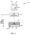
- Fig. 1 shows a computer system 10 constructed in accordance with the present invention.
- the computer system includes a host processor 12 that receives control inputs from an attached keyboard 14 and displays system responses on a display screen 16 of a display device 18 that is connected to the host processor.
- a cursor 20 is displayed on the display screen and can be used to designate system tasks, change the display, and the like.
- the computer system 10 includes two cursor control actuators, a display stick control device 22 and an optional display mouse control device 24.
- the cursor control actuators can be used to generate display commands that initiate tasks and display changes by using the actuators to move the cursor 20 on the display screen 16 to a task icon and then actuate, or "click", button switches 25 on the mouse or on a keyboard hand rest 26.
- the cursor control actuators of the system 10 also can be used to initiate display changes and the like without moving the cursor and without clicking the buttons 25.
- a simple directed tap or nudge to one of the control actuators automatically causes a display change or system task to be initiated, providing enhanced functionality.
- the user may select whether both cursor control actuators or, more typically, the stick controller 22 alone, shall have this enhanced functionality.
- the cursor control actuator(s) 22 (24) control movement of the display cursor 20 when they receive a steady force and perform a different function when they are quickly tapped, thereby increasing the number of display functions that can be quickly performed without increasing the number of control actuators, or the number of actuator operations, necessary to make a display change.
- the stick control device 22 of the keyboard 14 comprises a rigid, generally elongated rod, sometimes referred to as a joystick, that extends perpendicularly from approximately the middle of the keyboard, between the home position of a typist's two hands, and is sufficiently short so that it does not interfere with normal typing on the keyboard.
- the stick control device can comprise the TrackPoint II control device by the IBM Corporation, for example, which currently is one of the more advanced control devices of this kind and is described in U.S. Patent 5,764,219 "Controller for Improved Computer Pointing Devices" assigned to IBM Corporation and filed November 29, 1990.
- Lateral forces can be applied to the stick control device 22 to move the cursor 20 about on the display screen 16 in a generally intuitive manner. That is, applying a control force directed to the left or right of the keyboard 14 as illustrated in Fig. 1 will cause the cursor to move left or right, respectively, on the display. Similarly, applying a force directed toward the top or bottom of the keyboard as illustrated in Fig. 1 will move the cursor toward the top or bottom of the display.
- the stick control device 22 includes a force transducer array 28 that converts the applied forces into electrical signals that detect the direction and magnitude of the applied force and move the cursor 20.
- One or more associated switches such as the buttons 25 on the mouse 24 or hand rest 26 or an "enter” button (not illustrated) on the keyboard 14, are conventionally used to select cursor-targeted screens.
- the enhanced functionality of a control actuator such as the TrackPoint II type device described herein for the preferred embodiment, may in principle be extended to a mouse or external joystick control device.
- the host processor 12 comprises, for example, the processing unit of an IBM Corporation Model "PS/2" or "ThinkPad 750" personal computer or the like.
- the display device 18 comprises a conventional video display terminal or flat panel display.
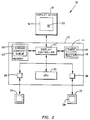
- Fig. 2 is a block diagram showing the computer system 10 in greater detail.
- the keyboard 14 is not illustrated, for simplicity.
- Fig. 2 shows that the host processor 12 includes a central processing unit (CPU) 32, which communicates with a display controller 34 and thereby controls the images displayed on the display screen 16 of the display device 18.
- the stick controller 22 and mouse 24 are connected to the display controller and CPU via respective stick and mouse interfaces 36 and 38.
- Fig. 2 also shows that the host processor 12 includes a memory 40, a portion of which is used as a cursor context queue 42.
- the cursor context queue stores display window identifiers as well as the cursor position within each display window.
- a tap signature identifier 44 recognizes forces applied to the stick controller 22 and mouse 24 that match a predetermined tap signature and thereby constitute directed taps for predetermined display functions.
- a force applied to the stick controller 22 is detected by the associated stick force transducer 28, which provides the magnitude and direction of the applied control force to the stick interface 36.
- the display controller 34 receives this information and provides it to the tap signature identifier 44.
- the tap signature identifier preferably includes a control actuator buffer 46 and timer 48 that permit comparison of a moving time interval of applied control actuator forces as represented by the transducer signal against a predetermined tap signature.
- the tap signature identifier can determine, for example, if the force applied to the stick controller 22 for the previous split-second's worth of time comprises a waveform that describes a tap comprising a sawtooth-type pulse having a rapidly rising leading edge and a slower falling trailing edge.
- control actuator buffer 46 continuously receives the applied force transducer signal and the tap signature identifier 44 performs correlation processing on the buffer contents to assess the likelihood that the applied force was a tap, an inadvertent undirected nudge, or the beginning of a continuous cursor control input.
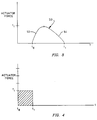
- Fig. 3 shows a chart that illustrates the tap signature waveform 50 that is used by the tap signature identifier 44 to determine when a display change will occur, as a function of time (on the horizontal axis) and control actuator force (on the vertical axis).
- the chart shows that the applied force begins at a time t 0 and has a duration of t t and includes a relatively rapidly rising leading edge 52 up to a peak force f t and a relatively slowly falling trailing edge 54. If the control actuator buffer 46 contents have a sufficiently high correlation coefficient with respect to a predetermined tap signature waveform, then the display controller performs the appropriate display change or system function.
- the tap signature identifier 44 can use a simpler tap signature criterion.
- the tap signature identifier can use the timer 48 to simply determine the time duration of the applied force and provide the information to the display controller 34, which then determines if display changes are warranted, based on the time duration and magnitude of the applied force. If the magnitude of the applied force was within a predetermined range of force values, as indicated by the control actuator transducer 28, and was indicated by the timer 48 as being applied to the control actuator for a predetermined short time interval and released, then the display controller 34 changes the display, as described further below. As soon as the force applied to the control actuator extends beyond the predetermined short time interval, such as would be the case for a continuous force, then the display controller moves the cursor 20 across the display screen 16 in accordance with the applied force, without otherwise changing the display screen.
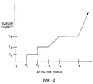
- Fig. 4 shows a chart that illustrates the simplest temporal signature criterion for a display change as a function of time (on the horizontal axis) and control actuator force (on the vertical axis).
- the shaded portion of the chart shows the duration and magnitude of control actuator force that results in the display change action.
- forces applied to the actuator 22 for less than a predetermined time interval t 1 and having a transducer signal magnitude less than f t will result in the display change described further below.
- the display change action can take place in response to a control actuator force having any magnitude, so long as the duration is less than the t 1 time interval.
- the t 1 time interval illustrated in Fig. 4 can be different from the t t time interval of the tap signature waveform illustrated in Fig. 3.
- the display controller 34 requires that a predetermined short time interval of no force application, a blank interval, precede the tap signature criteria illustrated in Fig. 3 and Fig. 4. In this way, active cursor display movement changes are not interpreted as display change taps. This eliminates, for example, changes in cursor movement direction from being interpreted as display change taps.
- the blank interval preferably is a relatively short time interval, approximately equal to the tap signature display change time interval.
- the timer 44 provides a convenient means for determining display change taps.
- the timer 48 of the tap signature identifier 44 is used so that only short duration control actuator forces initiate display changes other than cursor movement. This is to distinguish between short duration taps on the display control actuator 22 meant to change the display and continuous applications of force meant to initiate cursor movement.
- the display controller 34 detects short duration taps by detecting from the timer 48 the duration of force application. Preferably, only relatively low magnitude, short duration applications of force to the control actuators will result in a display change.
- forces applied to the control actuators for greater than a predetermined time interval will result in display cursor movement. Forces that are applied for no more than the predetermined time interval will result in a display change.
- Other responses can be selected, modified, or added, as described herein.
- the speed with which the cursor 20 is moved across the display screen can depend on the magnitude and duration of the applied control actuator force.
- the cursor 20 can be controlled, for example, according to the force applied to one of the control actuators as described in the co-pending application by EP 607 580 A entitled “Tactile Feedback Mechanism for Cursor Control” by IBM Corporation filed January 20, 1993.
- a graphical user interface is supported and the display device 18 displays a conventional window operating environment in which multiple windows can be displayed simultaneously on the display screen 16.
- each window represents a program or system operation that is "opened” and therefore is accessible when the cursor 20 is targeted within the window and a mouse or handrest button 25 is activated or an "enter" keystroke is executed.
- Multiple windows may be opened simultaneously and displayed on the display screen, which thereby constitutes a desktop display, such that the windows may be stacked or overlapped and some may be partially hidden from view.
- One of the overlapped windows generally the top-most window in a stack of windows, is designated the "active" window.
- the display changes that are initiated in response to tap signature forces, or display change taps can comprise a variety of actions.
- the computer system 10 can display a variety of system operating windows, well-known to those skilled in the art, on the display screen 16.
- Other responses to display change taps can comprise functions otherwise performed by programmable function keys, known as PF keys, or can be user-defined functions. If the force transducers of the control actuators can determine control actuator force as a combination of forces applied along a variety of axes, then a tap signature force applied along each axis can be associated with a different display change.
- control actuator comprises the control stick 22 extending from the keyboard 14, and if the associated transducer 28 can detect forces applied along an x-axis, a y-axis, and a z-axis, then different display changes can be associated with each of the three axes.
- the display controller 34 uses a cyclical cursor context queue 42 to keep track of the opened windows displayed on the display screen 16 as well as the last cursor location in each window.
- a cursor context comprises both the window status, or window being displayed, and the cursor location in the window.
- the cursor context queue can be used to keep a list of window status identifiers and cursor locations as windows are opened or become the active window, or the cursor context queue can be used to keep a list of windows and cursor locations as windows are placed on top of one another in the display, or dual queues can be maintained to keep track of both sets of information. Other techniques for keeping track of the open windows in the display and for keeping track of the active window will occur to those skilled in the art.
- control actuators can be used to selectively step through the contents of each respective cursor context queue that is defined. Regardless of the number of queues maintained by the display controller 34, one of the window identifiers is designated the active window and occupies the top spot in the display.
- the cursor context queue 42 includes an automatic queue and a user-defined queue.
- the automatic queue is automatically filled with window identifiers and corresponding cursor locations as a system user makes window display commands
- the user-defined queue is filled with window identifiers and corresponding cursor locations in response to user queue control commands.
- a window display command occurs when a user targets a window or command icon within a window using the cursor and makes a selection by clicking one of the mouse or handrest buttons 25 or the "enter" button, as described above.
- a user queue control command can comprise, for example, pressing a predetermined function key or a sequence of keyboard keys.
- the system 10 automatically stores the window status at the time of the command, including any drop-down menu or other command artifact displayed in the window, along with the cursor location in the window, into the automatic queue portion of the cursor context queue 42.
- the automatic queue eventually becomes filled and the queue is changed on a first-in-first-out basis. That is, new window display commands generate new cursor context entries that replace older cursor context entries in the automatic queue.
- window display commands that are triggered by targeting a menu item and pressing the "enter" button, which generate an automatic cursor context queue entry must be distinguished from enter button presses that are not associated with a window display command, which do not generate a cursor context queue entry.
- the cursor context comprising the window identifier and status as well as the cursor location at the time the window display command was issued, are placed in the next available location of the cursor context queue 42.
- the user can cycle through the automatic queue entries of the cursor context queue by repeatedly tapping the control actuator along one of the control axes, such as the x axis. Tapping the control stick in the leftward direction, for example, can move backward through the automatic queue while tapping the control stick in the rightward direction can move forward through the queue.
- a cursor context is placed in the user-defined queue when the user makes a predetermined queue control command, such as pressing a function key typically provided on the keyboard.
- the user can designate particular programs or windows to which the user might want to return after continuing with other actions.
- the user can cycle through the user-defined queue entries of the cursor context queue 42 by repeatedly tapping the control actuator along one of the control axes, such as the y axis.
- newly defined cursor contexts replace older cursor contexts in the queue.
- a user can return to prior windows and continue working from the last cursor position in each window by repeatedly tapping the control stick 22 along the y-axis. Tapping the control stick in the upward direction, for example, can move backward through the user-defined queue while tapping the control stick in the downward direction can move forward through the queue.
- cursor context queue 42 lists the windows in the order of screen placement, such as layers of overlapping windows, then each force matching the tap signature described above in connection with Fig. 3 or Fig. 4, comprising a tap signature force, applied in the direction of the x axis can be used to bring a different one of the placement queue windows to the top of the queue, thereby causing the associated window to be displayed as the new active, top-most window, along with the corresponding cursor location.
- each tap signature force applied in the direction of the y axis can be used to bring a different one of the time queue identifiers to the top of the queue, thereby causing the associated window to be displayed as the new active window, along with the corresponding cursor location.
- a tap signature force applied in the direction of the z axis can be used for another change.
- z axis force measurement may respond only to inwardly directed (pressing) forces and therefore a tap signature force applied in the z direction may be best suited to a toggling function such as selection of a predetermined, possibly user-defined, window or other display change.
- Fig. 5 shows a chart of cursor velocity as a function of the control actuator force.
- Fig. 5 shows that for forces below a predetermined magnitude of f 1 , no cursor movement will be initiated.
- f 1 and less than f 2 cursor movement will be at a relatively low rate of v 1 to make cursor placement easier.
- Control actuator forces having a magnitude greater than f 2 and less than f 3 will result in cursor movement at a second velocity v 2 .
- Control actuator forces greater than f 3 and less than f 4 have a linearly increasing velocity function up to velocity v 3 .
- the velocity v 3 approximately agrees with an eye-tracking limit speed and is constant for a relatively large range of forces from f 4 to f 5 to permit a user to press the actuator without losing the cursor on the display screen.
- control actuator forces having a magnitude greater than f 5 result in a steeply inclined velocity function to permit users to move the cursor across the screen almost instantaneously. It should be understood that the force value f 1 indicated in Fig. 5 for cursor movement can be a different magnitude than the force value f t indicated in Fig. 4 for a display change.
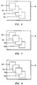
- Figs. 6, 7, and 8 show windows that are overlapped according to their relative positions in the cursor context queue 42 and illustrate display screen changes as a result of a succession of tap signature forces applied along one of the axes.
- forces applied along the x-axis are used to select cursor contexts from the automatic queue of the cursor context queue 42 so that forces applied in the rightward (or leftward) x direction will activate the next window (or previous window) in the queue and restore the cursor to its corresponding location in the window.
- forces applied along the x axis can be used to select from a queue containing overlapped, stacked display window displays so that forces applied in the rightward (or leftward) x direction will activate the window to the right (or left) of the top display window, such that the newly-defined top-most window is immediately active and the cursor location is set to its last active position in that window, as indicated from the cursor context queue 42.
- Fig. 6 shows the display screen 16 with a series of four overlapped display windows 102, 104, 106, 108 displayed in a manner well-known to those skilled in the art, forming a stack with one window 102 at the top of the stack.
- Fig. 7 shows the same windows after an applied force having the recognized display change tap signature has been applied to the right.
- a new top-most window 104 has replaced the prior top-most window 102 from Fig. 6.
- the new top-most window corresponds to the next display and corresponding cursor location from the cursor context queue.
- An additional rightward display change tap results in the display shown in Fig. 8.
- the process will cycle or "wrap" so that two rightward display change taps from the display of Fig.
- display change taps applied substantially along different axes can control different display changes.
- Display change taps applied along the y-axis of the control actuator can be used, for example, to select window displays from the user-defined queue of the cursor context queue 42.
- y-axis taps can be used to select different window displays from a queue containing displays and corresponding cursor locations in the time order in which each window was opened.
- the GUI may by default create a display, in spatial and temporal window match, user functions such as zooming or dragging windows may alter this correspondence.
- the use of y-axis taps for a temporal queue may offer added ease of use.
- display change taps applied along the x-axis can be used to cycle the windows in an overlapped stack so that the top window is moved to the bottom window and the second window is moved to the top
- display change taps applied along the y-axis can be used to cycle the window at the bottom of the stack to the top while the previous top display window is moved down by one.
- the stick control device 22 can detect movement along the z-axis.
- the stick detects forces directed along the z direction. That is, only display change taps pushing axially (pressing) on the stick controller are detected to indicate state changes, and no pulling axial forces are registered or recognized.
- the display controller 34 can respond to z-axis forces, for example, by opening a predetermined root window, such as a main window or a program manager window, or can be used to open a user-defined window.
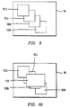
- Figs. 9 and 10 illustrate a display change such as described above for z-axis forces.
- Fig. 9 four overlapped and partially hidden windows 102, 104, 106, 108 are shown.
- Fig. 10 illustrates that the display processor 34 responds to a z-axis display change force by displaying a root window 110 on top of the already-displayed windows.
- the root window can comprise, for example, a main window or program manager window, known to those skilled in the art.
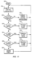
- Fig. 11 is a flow diagram that illustrates the processing steps of the computer system as illustrated in Fig. 1.
- the processing routine begins with the start box numbered 202.
- the next flow diagram box 204 indicates that the status of the control actuator is sampled.
- Fig. 11 indicates that the control actuator can detect forces applied as a combination of forces along an x axis, a y axis, and a z axis.
- decision box 206 a tap signature display change force is tested for by the tap signature identifier. If the applied force is not a display change force, then normal cursor control processing is implemented at the flow diagram box numbered 208. Processing then returns to the sampling box 204.
- the force is checked at the decision box numbered 210 to determine if the tap was oriented along the x-axis. An affirmative response at box 210 results in the initiation of processing an x-axis force, indicated at the flow diagram box numbered 212. Processing then returns to the sampling box numbered 204. If the applied force was not an x-axis force, then at decision box 214, a y-axis force is checked. If the force was applied along the y-axis, then processing for the y-axis is initiated at the box numbered 216.
- a recognizable display change tap signature such as the sawtooth waveform illustrated in Fig. 3 or the short duration, low-magnitude criteria illustrated in Fig. 4
- Processing then returns to the sampling box numbered 204.
- z-axis processing is initiated at the flow diagram box numbered 220.
- the applied force had the requisite waveform shape or short duration, but was not directed primarily along either the x-axis, the y-axis, or the z-axis, then the applied force is considered an inadvertent force and is ignored, as indicated by the flow diagram box numbered 222. Processing then returns to the sampling box numbered 204.
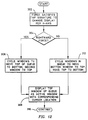
- Fig. 12 illustrates the processing for an x-axis force (box 212 of Fig. 10) according to the preferred embodiment, in which x-axis forces are mapped to automatically defined cursor contexts. That is, the x-axis forces cause changes to the cursor context queue 42 in which window display identifiers and cursor locations are stacked by relative position in accordance with the order in which window commands were generated.
- the tap signature to change the window display is detected at the box numbered 302.
- the display controller cycles the entries in the cursor context queue depending on whether the force was applied leftward or rightward, as indicated by the decision box numbered 304.
- the window displays are cycled such that the cursor context previously at the top of the queue is moved to the bottom and the previously second cursor context is moved to the top. This is indicated at the flow diagram box numbered 306.
- the window display at the top of the queue is designated the new active window and is displayed on the display screen, along with the corresponding cursor location, as indicated at the flow diagram box numbered 308.
- the computer system processing resumes at the continuation box numbered 310. That is, processing returns to box 204 of Fig. 11.
- the window displays are cycled such that the cursor context at the bottom of the queue is moved to the top and the former top cursor context becomes the second, as indicated at the box numbered 312.
- the new top cursor context comprises a window with corresponding cursor location at box 308, and processing continues at box 310.
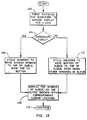
- Fig. 13 illustrates the processing for a y-axis force (box 216 of Fig. 11) according to the preferred embodiment, in which y-axis forces are mapped to user-defined window displays.
- the y-axis forces cause changes to the cursor context queue 42.
- the tap signature to change the window display is detected at the flow diagram box numbered 402.
- the display controller cycles the entries in the cursor context queue depending on whether the tap was downward or upward, as indicated by the decision box numbered 404.
- the window displays are cycled such that the second cursor context in the queue is moved to the top of the queue as the top is moved to the bottom. This is indicated at the flow diagram box numbered 406.
- the cursor context at the top of the cursor context queue is displayed as the active window on the display screen, along with the corresponding cursor location, as indicated at the flow diagram box numbered 408.
- the computer system processing resumes at the continuation box numbered 410.
- the window displays are cycled such that the cursor context previously at the bottom of the queue is moved to the top of the cursor context queue and the remaining cursor contexts are pushed down in the queue, as indicated at the flow diagram box numbered 412.
- the new top cursor context in the queue is displayed as the new active window and is displayed with corresponding cursor location at box 408 and computer system processing continues at box 410. It should be noted that, because not all windows will be overlapped, the time-ordered cursor context queue will not necessarily correspond to the placement-ordered cursor context queue.
- Fig. 14 illustrates the processing for a z-axis display change tap (box 220 in Fig. 11) according to the preferred embodiment, in which z-axis taps are mapped to activating a predetermined root window.
- the tap signature to change the window display is detected at the box numbered 502.
- the z-axis input is detected as a push to the control actuator, indicating a change in state.
- the display controller checks to determine if the root window is active. If it is active, then at the flow diagram box numbered 506 the display controller returns from the root window to the prior active window, along with the corresponding cursor position. Processing continues at box 508.
- the display controller displays the predetermined window, such as a root window, along with the corresponding cursor location.
- the predetermined window such as a root window
- the root window identifier is placed in the top cursor context queue position or otherwise indicated as the active window. Processing resumes at the flow diagram box numbered 508. It should be noted, once again, that many different parameters can be selected for the respective control axis processing and cursor context queue ordering.
- the pointing system described above provides a computer system in which a control actuator ordinarily controls movement of a cursor on a computer system display device in response to continuous force applications and changes the display in response to applications of force satisfying a tap signature criterion having, for example, a predetermined time interval and range of force values.
- a tap signature criterion having, for example, a predetermined time interval and range of force values.
- a different system function can be assigned.
- the functions can comprise predetermined display changes, such as described above in connection with Figs. 6-10, or can duplicate functions provided by programmable function keys of conventional computer keyboards, or can be user-defined functions. Regardless of the system function, the control actuator provides cursor movement control and enhanced system access.
Landscapes
- Engineering & Computer Science (AREA)
- Theoretical Computer Science (AREA)
- General Engineering & Computer Science (AREA)
- Human Computer Interaction (AREA)
- Physics & Mathematics (AREA)
- General Physics & Mathematics (AREA)
- User Interface Of Digital Computer (AREA)
- Position Input By Displaying (AREA)
- Digital Computer Display Output (AREA)
- Controls And Circuits For Display Device (AREA)
Claims (17)
- Zeigersystem zum Steuern einer grafischen Benutzerschnittstelle (16), das auf einer Anzeigeeinheit eines Computersystems (18) angezeigt wird, mit einem Steuerarm (22) zum Verschieben eines Anzeigecursors (20) der grafischen Benutzerschnittstelle (16) und einem Kraftwandler (28), der Kräfte feststellt, die an dem Steuerarm (22) angewandt werden, wobei das Zeigersystem eine Erkennungseinrichtung für ein Betätigungsmuster und eine Anzeigesteuereinheit umfasst;wobei das Zeigersystem dadurch gekennzeichnet ist, dass:die Erkennungseinrichtung für ein Betätigungsmuster (44) Kräfte erkennt, die an dem Steuerarm (22) in seitlichen Richtungen angewandt werden, und feststellt, ob die seitlichen Kräfte während eines ersten vorherbestimmten Zeitraums angewendet werden und dann freigegeben werden, so dass die angewandten Kräfte einer von mehreren vorherbestimmten Erkennungseinrichtung für ein Betätigungsmuster entsprechen, die jeder durch eine Funktion von Größe und Richtung der angewandten Kraft definiert sind, die während des ersten vorherbestimmten Zeitraums auftritt, und dadurch eine Anzeigeänderungs-Betätigung enthalten; unddie Anzeigesteuereinheit (34) auf seitliche Kräfte reagiert, die an dem Steuerarm (22) angewandt werden, und durch die Erkennungseinrichtung für ein Betätigungsmuster (44) gekennzeichnet wird, dass sie Anzeigeänderungs-Betätigungen umfasst, indem Anzeigeaktionen entsprechend den Anzeigeänderungs-Betätigungen eingeleitet werden, und die anderenfalls auf die seitlichen Kräfte des Steuerarms durch Verschieben des Cursors (20) über die Anzeige (18) entsprechend den am Steuerarm angewandten Kräften antwortet.
- Zeigersystem nach Anspruch 1, wobei die Anzeigesteuereinheit (34) das Einleiten der ersten Anzeigeaktion nur veranlasst, wenn ein zweiter vorherbestimmter Zeitraum, während dessen keine Kraft am Steuerarm festgestellt wird, dem ersten Zeitraum vorausgeht.
- Zeigersystem nach Anspruch 1, wobei die Anzeigeeinheit (18) eine Vielzahl überlappender Computersystembetriebsfenster (102-108) anzeigt und die erste Anzeigeaktion das Verschieben eines anderen der Fenster (102-108) in den oberen Teil der Anzeige umfasst.
- Zeigersystem nach Anspruch 3, wobei das Zeigersystem eine Cursorkontextschlange umfasst, die eine Liste der angezeigten Betriebsfenster (102-108) und entsprechender Cursorpositionen für jedes der Fenster (102-108) enthält, so dass das Betriebsfenster an der Spitze der Schlange und die entsprechende Cursorposition angezeigt werden.
- Zeigersystem nach Anspruch 1, wobei der Steuerarm (22) eine Stab-Steuereinheit umfasst.
- Zeigersystem nach Anspruch 5, wobei:der Kraftwandler (28) die Kraft des Steuerarms als eine Kombination der jeweils entlang einer x-Achse oder einer y-Achse des Steuerarms angewandten Kräfte bestimmen kann; unddie Anzeigesteuereinheit (34) das Einleiten der ersten Anzeigeaktion nur veranlasst, wenn die Kraft des Steuerarms im Wesentlichen entweder entlang der x-Achse oder der y-Achse angewandt wird.
- Zeigersystem nach Anspruch 5, wobei:der Kraftwandler (28) die Kraft des Steuerarms als eine Kombination der in einer x-y-Ebene und entlang einer z-Achse angewandten Kräfte feststellen kann; unddie Anzeigesteuereinheit (34) das Einleiten der ersten Anzeigeaktion veranlasst, wenn die Kraft im Wesentlichen nur in der x-y-Ebene angewandt wird, und das Einleiten einer zweiten Anzeigeaktion veranlasst, wenn die Kraft im Wesentlichen nur entlang der z-Achse angewandt wird.
- Zeigersystem nach Anspruch 5, wobei:der Kraftwandler (28) die Kraft des Steuerarms als eine Kombination der entlang einer x-Achse, einer y-Achse und einer z-Achse angewandten Kräfte feststellen kann; unddie Anzeigesteuereinheit (34) das Einleiten der ersten Anzeigeaktion veranlasst, wenn die Kraft im Wesentlichen nur entlang der x-Achse angewandt wird, das Einleiten einer zweiten Anzeigeaktion veranlasst, wenn die Kraft im Wesentlichen nur entlang der y-Achse angewandt wird, und das Einleiten einer dritten Anzeigeaktion veranlasst, wenn die Kraft im Wesentlichen nur entlang der z-Achse angewandt wird.
- Zeigersystem nach irgendeinem der Ansprüche 6, 7 oder 8, wobei die Anzeigeeinheit (18) eine Vielzahl überlappter Computersystembetriebsfenster (102-108) anzeigt und die erste Anzeigeaktion das Verschieben eines anderen der Fenster (102-108) in den oberen Teil der Anzeige (18) umfasst.
- Zeigersystem nach den Ansprüchen 6 und 9, wobei die Anzeigesteuereinheit (34) das Einleiten der ersten Anzeigeaktion nur veranlasst, wenn die Kraft des Steuerarms im Wesentlichen entlang der x-Achse angewandt wird, und das Einleiten der zweiten Anzeigeaktion nur veranlasst, wenn die Kraft des Steuerarms im Wesentlichen entlang der y-Achse angewandt wird.
- Zeigersystem nach Anspruch 10, wobei:das System weiterhin eine Cursorkontextschlange enthält, die eine Liste der angezeigten Betriebsfenster (102-108) und entsprechender Cursorpositionen für jedes der Fenster (102-108) enthält und die erste Anzeigeaktion das Anzeigen des Betriebsfensters an der Spitze der Schlange und der entsprechenden Cursorposition in dem Fenster umfasst.
- Zeigersystem nach Anspruch 11, wobei:die Cursorkontextschlange automatische Schlangeneinträge und benutzerdefinierte Einträge enthält, so dass aktuelle Fensteranzeigen (102-108) und entsprechende Cursorpositionen automatisch als Antwort auf Befehle der Benutzerfensteranzeige und aktuelle Fensteranzeigen (102-108) in die Cursorkontextschlange geladen werden, und entsprechende Cursorpositionen als Antwort auf vorherbestimmte Schlangensteuerbefehle des Benutzers in die Cursorkontextschlange geladen werden.
- Zeigersystem nach Anspruch 12, wobei die Anzeigesteuereinheit (34) den obersten Cursorkontext von den automatischen Schlangeneinträgen der Cursorkontextschlange als Antwort auf Anzeigeänderungs-Betätigungen entlang der x-Achse zyklisch durchläuft und den obersten Cursorkontext als das aktive Fenster anzeigt und durch den obersten Cursorkontext aus den benutzerdefinierten Schlangeneinträgen der Cursorkontextschlange als Antwort auf Anzeigeänderungs-Betätigungen entlang der y-Achse zyklisch durchläuft und den obersten Cursorkontext als das aktive Fenster anzeigt.
- Zeigersystem nach den Ansprüchen 8 und 9, wobei:die Anzeigeeinheit (18) eine Vielzahl von überlappten Computersystembetriebsfenstern (102-108) anzeigt; unddas System weiterhin eine Cursorkontextschlange einschließt, die eine Liste der angezeigten Betriebsfenster (102-108) in der Reihenfolge der Überlappung enthält und entsprechende Cursorpositionen für jedes der Fenster (102-108) enthält, so dass das Betriebsfenster an der Spitze der Schlange das oberste angezeigte Fenster ist und die anderen Fenster in der Schlange entsprechend ihrer Reihenfolge in der Schlange überlappt werden.
- Zeigersystem nach Anspruch 14, wobei die erste Anzeigeaktion das zyklische Durchlaufen der Einträge in der Cursorkontextschlange enthält, so dass das zweite überlappte Fenster an die Spitze der Schlange gebracht wird, wobei die zweite Anzeigeaktion das zyklische Durchlaufen der Einträge in der Cursorkontextschlange umfasst, so dass der untere Cursorkontext an die Spitze der Cursorkontextschlange gebracht wird, und die dritte Anzeigeaktion das Verschieben eines vorherbestimmten der Cursorkontexte an die Spitze der Cursorkontextschlange umfasst.
- Computersystem, das Folgendes umfasst:einen Host-Prozessor (12);eine Tastatur (14) mit einer Vielzahl von im Wesentlichen koplanaren alphanumerischen Tasten, die das Eingeben von Daten in den Host-Prozessor (12) ermöglichen;eine Anzeigeeinheit (18), die einen Cursor (20) anzeigt;einen Cursorsteuerarm (22), der betätigt werden kann, um die Verschiebung des Anzeigecursors (20) zu veranlassen;einen Kraftwandler (28), der Richtung und Größe der an dem Steuerarm (22) angewandten Kräfte feststellt; und ein Zeigersystem gemäß irgendeinem der vorhergehenden Ansprüche.
- Verfahren zum Antworten auf Kräfte, die an einem Cursorsteuerarm (22) angewandt werden, der eine grafische Benutzerschnittstelle (16) steuert, die auf einer Anzeigeeinheit eines Computersystems (18) angezeigt wird, wobei das Verfahren die folgenden Schritte umfasst:Feststellen von Kräften, die an dem Steuerarm (22) in seitlichen Richtungen angewandt werden;Feststellen, ob die seitlichen Kräfte während eines ersten vorherbestimmten Zeitraums angewandt und dann freigegeben werden, so dass die angewandten Kräfte einer von mehreren vorherbestimmten Erkennungseinrichtung für ein Betätigungsmuster entsprechen, von denen jeder durch eine Funktion von Betrag und Richtung der angewandten Kraft über den ersten vorherbestimmten Zeitraum definiert sind, und dadurch eine Anzeigeänderungs-Betätigungen umfasst;Einleiten von Anzeigeaktionen entsprechend Anzeigeänderungs-Betätigungen als Antwort auf seitliche Kräfte, die an dem Steuerarm (22) angewandt werden und für die durch den Schritt des Vorherbestimmens gekennzeichnet wird, dass sie Anzeigeänderungs-Betätigungen enthalten; undanderenfalls Antworten auf seitliche Kräfte des Steuerarms durch Verschieben des Cursors (20) über die Anzeige (18) entsprechend den am Steuerarm (22) angewandten Kräften.
Applications Claiming Priority (2)
| Application Number | Priority Date | Filing Date | Title |
|---|---|---|---|
| US17587893A | 1993-12-30 | 1993-12-30 | |
| US175878 | 1993-12-30 |
Publications (2)
| Publication Number | Publication Date |
|---|---|
| EP0662654A1 EP0662654A1 (de) | 1995-07-12 |
| EP0662654B1 true EP0662654B1 (de) | 2000-04-26 |
Family
ID=22642029
Family Applications (1)
| Application Number | Title | Priority Date | Filing Date |
|---|---|---|---|
| EP94308937A Expired - Lifetime EP0662654B1 (de) | 1993-12-30 | 1994-12-01 | Programmzugang in einer graphischen Benutzerschnittstelle |
Country Status (8)
| Country | Link |
|---|---|
| US (1) | US5699082A (de) |
| EP (1) | EP0662654B1 (de) |
| JP (1) | JP2610114B2 (de) |
| KR (1) | KR0167464B1 (de) |
| CN (1) | CN1091898C (de) |
| DE (1) | DE69424145T2 (de) |
| MY (1) | MY117103A (de) |
| TW (1) | TW279949B (de) |
Families Citing this family (163)
| Publication number | Priority date | Publication date | Assignee | Title |
|---|---|---|---|---|
| US7113171B2 (en) | 1997-06-10 | 2006-09-26 | Mark Vayda | Universal input device |
| US5973670A (en) * | 1996-12-31 | 1999-10-26 | International Business Machines Corporation | Tactile feedback controller for computer cursor control device |
| US8279169B2 (en) * | 1997-06-10 | 2012-10-02 | Mark Vayda | Universal input device and system |
| US20030107557A1 (en) * | 1997-07-30 | 2003-06-12 | Gateway, Inc. | Control of unintended single-tap actuation of a computer touch pad pointing device |
| US5926175A (en) * | 1997-09-30 | 1999-07-20 | Compaq Computer Corporation | Method and apparatus to prevent top-most windows from interfering with TV mode in a PC/TV |
| GB2335024A (en) * | 1998-03-06 | 1999-09-08 | Ibm | Joystick for portable computer system |
| US6098184A (en) * | 1998-05-08 | 2000-08-01 | Spotware Technologies, Inc. | Method for improving mouse performance and virtual device driver therefor |
| WO1999060556A1 (en) * | 1998-05-20 | 1999-11-25 | Chan Kwan Ho | Finger controlled computer mouse |
| US6452586B1 (en) | 1998-11-30 | 2002-09-17 | Microsoft Corporation | Computer input device providing tactile feedback |
| US6697506B1 (en) * | 1999-03-17 | 2004-02-24 | Siemens Corporate Research, Inc. | Mark-free computer-assisted diagnosis method and system for assisting diagnosis of abnormalities in digital medical images using diagnosis based image enhancement |
| US7170499B1 (en) * | 1999-05-25 | 2007-01-30 | Silverbrook Research Pty Ltd | Handwritten text capture via interface surface |
| US6728675B1 (en) * | 1999-06-03 | 2004-04-27 | International Business Machines Corporatiion | Data processor controlled display system with audio identifiers for overlapping windows in an interactive graphical user interface |
| US8645137B2 (en) | 2000-03-16 | 2014-02-04 | Apple Inc. | Fast, language-independent method for user authentication by voice |
| US6983063B1 (en) | 2000-06-29 | 2006-01-03 | Siemens Corporate Research, Inc. | Computer-aided diagnosis method for aiding diagnosis of three dimensional digital image data |
| US7257777B1 (en) * | 2000-07-19 | 2007-08-14 | International Business Machines Corporation | System and method for automatic control of window viewing |
| US6944330B2 (en) * | 2000-09-07 | 2005-09-13 | Siemens Corporate Research, Inc. | Interactive computer-aided diagnosis method and system for assisting diagnosis of lung nodules in digital volumetric medical images |
| FR2821446B1 (fr) * | 2001-02-26 | 2003-06-13 | Eads Airbus Sa | Dispositif de dialogue d'aeronef, pour dialoguer avec un systeme dudit aeronef |
| JPWO2003052569A1 (ja) * | 2001-12-07 | 2005-04-28 | 株式会社エヌ・ティ・ティ・ドコモ | 移動通信端末、アプリケーション実行制御方法、アプリケーション実行制御プログラム及びコンピュータ読み取り可能な記録媒体 |
| US6690387B2 (en) * | 2001-12-28 | 2004-02-10 | Koninklijke Philips Electronics N.V. | Touch-screen image scrolling system and method |
| EP1704755A4 (de) * | 2003-12-08 | 2009-12-09 | Thomson Licensing | System und verfahren zum anlegen von leistung an hochintensitäts-entladungslampen |
| US8744852B1 (en) * | 2004-10-01 | 2014-06-03 | Apple Inc. | Spoken interfaces |
| US8677377B2 (en) | 2005-09-08 | 2014-03-18 | Apple Inc. | Method and apparatus for building an intelligent automated assistant |
| KR20070036429A (ko) * | 2005-09-29 | 2007-04-03 | 엘지전자 주식회사 | 문자편집 기능이 구비되는 이동통신 단말기 및 그 동작방법 |
| US8689134B2 (en) * | 2006-02-24 | 2014-04-01 | Dana W. Paxson | Apparatus and method for display navigation |
| CN100517205C (zh) * | 2006-04-21 | 2009-07-22 | 邱波 | 用于it领域的同时多维、增速、省空间的系统显示方法 |
| US9318108B2 (en) | 2010-01-18 | 2016-04-19 | Apple Inc. | Intelligent automated assistant |
| US8675847B2 (en) | 2007-01-03 | 2014-03-18 | Cisco Technology, Inc. | Scalable conference bridge |
| CN101246382B (zh) | 2007-02-14 | 2011-09-28 | 普安科技股份有限公司 | 可以容置不同尺寸硬盘的数据储存系统 |
| US8977255B2 (en) | 2007-04-03 | 2015-03-10 | Apple Inc. | Method and system for operating a multi-function portable electronic device using voice-activation |
| WO2008131544A1 (en) * | 2007-04-26 | 2008-11-06 | University Of Manitoba | Pressure augmented mouse |
| US9330720B2 (en) | 2008-01-03 | 2016-05-03 | Apple Inc. | Methods and apparatus for altering audio output signals |
| US8996376B2 (en) | 2008-04-05 | 2015-03-31 | Apple Inc. | Intelligent text-to-speech conversion |
| US10496753B2 (en) | 2010-01-18 | 2019-12-03 | Apple Inc. | Automatically adapting user interfaces for hands-free interaction |
| TWI419041B (zh) * | 2008-06-06 | 2013-12-11 | Hon Hai Prec Ind Co Ltd | 控制觸摸屏圖示顯示之方法 |
| JP2010020502A (ja) * | 2008-07-10 | 2010-01-28 | Alps Electric Co Ltd | ポインティングデバイス |
| US20100030549A1 (en) | 2008-07-31 | 2010-02-04 | Lee Michael M | Mobile device having human language translation capability with positional feedback |
| WO2010067118A1 (en) | 2008-12-11 | 2010-06-17 | Novauris Technologies Limited | Speech recognition involving a mobile device |
| US9141087B2 (en) | 2009-04-26 | 2015-09-22 | Nike, Inc. | Athletic watch |
| BRPI1016159A2 (pt) * | 2009-04-26 | 2018-08-07 | Nike Int Ltd | "dispositivo para monitorar o desempenho atlético de um usuário, e, dispositivo portátil de monitoramento de atividade atlética." |
| US20100295774A1 (en) * | 2009-05-19 | 2010-11-25 | Mirametrix Research Incorporated | Method for Automatic Mapping of Eye Tracker Data to Hypermedia Content |
| US10241752B2 (en) | 2011-09-30 | 2019-03-26 | Apple Inc. | Interface for a virtual digital assistant |
| US10706373B2 (en) | 2011-06-03 | 2020-07-07 | Apple Inc. | Performing actions associated with task items that represent tasks to perform |
| US9858925B2 (en) | 2009-06-05 | 2018-01-02 | Apple Inc. | Using context information to facilitate processing of commands in a virtual assistant |
| US10241644B2 (en) | 2011-06-03 | 2019-03-26 | Apple Inc. | Actionable reminder entries |
| US9431006B2 (en) | 2009-07-02 | 2016-08-30 | Apple Inc. | Methods and apparatuses for automatic speech recognition |
| US10553209B2 (en) | 2010-01-18 | 2020-02-04 | Apple Inc. | Systems and methods for hands-free notification summaries |
| US10276170B2 (en) | 2010-01-18 | 2019-04-30 | Apple Inc. | Intelligent automated assistant |
| US10705794B2 (en) | 2010-01-18 | 2020-07-07 | Apple Inc. | Automatically adapting user interfaces for hands-free interaction |
| US10679605B2 (en) | 2010-01-18 | 2020-06-09 | Apple Inc. | Hands-free list-reading by intelligent automated assistant |
| US8682667B2 (en) | 2010-02-25 | 2014-03-25 | Apple Inc. | User profiling for selecting user specific voice input processing information |
| US9262002B2 (en) * | 2010-11-03 | 2016-02-16 | Qualcomm Incorporated | Force sensing touch screen |
| US10762293B2 (en) | 2010-12-22 | 2020-09-01 | Apple Inc. | Using parts-of-speech tagging and named entity recognition for spelling correction |
| US9262612B2 (en) | 2011-03-21 | 2016-02-16 | Apple Inc. | Device access using voice authentication |
| US10057736B2 (en) | 2011-06-03 | 2018-08-21 | Apple Inc. | Active transport based notifications |
| US9417754B2 (en) | 2011-08-05 | 2016-08-16 | P4tents1, LLC | User interface system, method, and computer program product |
| US8994660B2 (en) | 2011-08-29 | 2015-03-31 | Apple Inc. | Text correction processing |
| US20140040819A1 (en) * | 2011-09-09 | 2014-02-06 | Adobe Systems Incorporated | Methods and systems for managing the presentation of windows on a display device |
| US10134385B2 (en) | 2012-03-02 | 2018-11-20 | Apple Inc. | Systems and methods for name pronunciation |
| US9483461B2 (en) | 2012-03-06 | 2016-11-01 | Apple Inc. | Handling speech synthesis of content for multiple languages |
| CN103309583B (zh) * | 2012-03-09 | 2016-01-20 | 艾默生过程控制流量技术有限公司 | 对操作时间进行显示的变送器 |
| US9280610B2 (en) | 2012-05-14 | 2016-03-08 | Apple Inc. | Crowd sourcing information to fulfill user requests |
| US9721563B2 (en) | 2012-06-08 | 2017-08-01 | Apple Inc. | Name recognition system |
| US9495129B2 (en) | 2012-06-29 | 2016-11-15 | Apple Inc. | Device, method, and user interface for voice-activated navigation and browsing of a document |
| US9576574B2 (en) | 2012-09-10 | 2017-02-21 | Apple Inc. | Context-sensitive handling of interruptions by intelligent digital assistant |
| US9547647B2 (en) | 2012-09-19 | 2017-01-17 | Apple Inc. | Voice-based media searching |
| US9265458B2 (en) | 2012-12-04 | 2016-02-23 | Sync-Think, Inc. | Application of smooth pursuit cognitive testing paradigms to clinical drug development |
| CN104969289B (zh) | 2013-02-07 | 2021-05-28 | 苹果公司 | 数字助理的语音触发器 |
| US9380976B2 (en) | 2013-03-11 | 2016-07-05 | Sync-Think, Inc. | Optical neuroinformatics |
| US9368114B2 (en) | 2013-03-14 | 2016-06-14 | Apple Inc. | Context-sensitive handling of interruptions |
| WO2014144579A1 (en) | 2013-03-15 | 2014-09-18 | Apple Inc. | System and method for updating an adaptive speech recognition model |
| KR101759009B1 (ko) | 2013-03-15 | 2017-07-17 | 애플 인크. | 적어도 부분적인 보이스 커맨드 시스템을 트레이닝시키는 것 |
| WO2014197336A1 (en) | 2013-06-07 | 2014-12-11 | Apple Inc. | System and method for detecting errors in interactions with a voice-based digital assistant |
| US9582608B2 (en) | 2013-06-07 | 2017-02-28 | Apple Inc. | Unified ranking with entropy-weighted information for phrase-based semantic auto-completion |
| WO2014197334A2 (en) | 2013-06-07 | 2014-12-11 | Apple Inc. | System and method for user-specified pronunciation of words for speech synthesis and recognition |
| WO2014197335A1 (en) | 2013-06-08 | 2014-12-11 | Apple Inc. | Interpreting and acting upon commands that involve sharing information with remote devices |
| US10176167B2 (en) | 2013-06-09 | 2019-01-08 | Apple Inc. | System and method for inferring user intent from speech inputs |
| KR101959188B1 (ko) | 2013-06-09 | 2019-07-02 | 애플 인크. | 디지털 어시스턴트의 둘 이상의 인스턴스들에 걸친 대화 지속성을 가능하게 하기 위한 디바이스, 방법 및 그래픽 사용자 인터페이스 |
| WO2014200731A1 (en) | 2013-06-13 | 2014-12-18 | Apple Inc. | System and method for emergency calls initiated by voice command |
| KR101749009B1 (ko) | 2013-08-06 | 2017-06-19 | 애플 인크. | 원격 디바이스로부터의 활동에 기초한 스마트 응답의 자동 활성화 |
| CN104469256B (zh) * | 2013-09-22 | 2019-04-23 | 思科技术公司 | 沉浸式和交互式的视频会议房间环境 |
| US9620105B2 (en) | 2014-05-15 | 2017-04-11 | Apple Inc. | Analyzing audio input for efficient speech and music recognition |
| US10592095B2 (en) | 2014-05-23 | 2020-03-17 | Apple Inc. | Instantaneous speaking of content on touch devices |
| US9502031B2 (en) | 2014-05-27 | 2016-11-22 | Apple Inc. | Method for supporting dynamic grammars in WFST-based ASR |
| US10289433B2 (en) | 2014-05-30 | 2019-05-14 | Apple Inc. | Domain specific language for encoding assistant dialog |
| US9966065B2 (en) | 2014-05-30 | 2018-05-08 | Apple Inc. | Multi-command single utterance input method |
| US9842101B2 (en) | 2014-05-30 | 2017-12-12 | Apple Inc. | Predictive conversion of language input |
| US9430463B2 (en) | 2014-05-30 | 2016-08-30 | Apple Inc. | Exemplar-based natural language processing |
| US9633004B2 (en) | 2014-05-30 | 2017-04-25 | Apple Inc. | Better resolution when referencing to concepts |
| US10170123B2 (en) | 2014-05-30 | 2019-01-01 | Apple Inc. | Intelligent assistant for home automation |
| US9734193B2 (en) | 2014-05-30 | 2017-08-15 | Apple Inc. | Determining domain salience ranking from ambiguous words in natural speech |
| US9715875B2 (en) | 2014-05-30 | 2017-07-25 | Apple Inc. | Reducing the need for manual start/end-pointing and trigger phrases |
| US9760559B2 (en) | 2014-05-30 | 2017-09-12 | Apple Inc. | Predictive text input |
| US10078631B2 (en) | 2014-05-30 | 2018-09-18 | Apple Inc. | Entropy-guided text prediction using combined word and character n-gram language models |
| US9785630B2 (en) | 2014-05-30 | 2017-10-10 | Apple Inc. | Text prediction using combined word N-gram and unigram language models |
| US9338493B2 (en) | 2014-06-30 | 2016-05-10 | Apple Inc. | Intelligent automated assistant for TV user interactions |
| US10659851B2 (en) | 2014-06-30 | 2020-05-19 | Apple Inc. | Real-time digital assistant knowledge updates |
| US10291597B2 (en) | 2014-08-14 | 2019-05-14 | Cisco Technology, Inc. | Sharing resources across multiple devices in online meetings |
| US10446141B2 (en) | 2014-08-28 | 2019-10-15 | Apple Inc. | Automatic speech recognition based on user feedback |
| US9818400B2 (en) | 2014-09-11 | 2017-11-14 | Apple Inc. | Method and apparatus for discovering trending terms in speech requests |
| US10789041B2 (en) | 2014-09-12 | 2020-09-29 | Apple Inc. | Dynamic thresholds for always listening speech trigger |
| US10074360B2 (en) | 2014-09-30 | 2018-09-11 | Apple Inc. | Providing an indication of the suitability of speech recognition |
| US9646609B2 (en) | 2014-09-30 | 2017-05-09 | Apple Inc. | Caching apparatus for serving phonetic pronunciations |
| US9886432B2 (en) | 2014-09-30 | 2018-02-06 | Apple Inc. | Parsimonious handling of word inflection via categorical stem + suffix N-gram language models |
| US10127911B2 (en) | 2014-09-30 | 2018-11-13 | Apple Inc. | Speaker identification and unsupervised speaker adaptation techniques |
| US9668121B2 (en) | 2014-09-30 | 2017-05-30 | Apple Inc. | Social reminders |
| US10552013B2 (en) | 2014-12-02 | 2020-02-04 | Apple Inc. | Data detection |
| US9711141B2 (en) | 2014-12-09 | 2017-07-18 | Apple Inc. | Disambiguating heteronyms in speech synthesis |
| US10542126B2 (en) | 2014-12-22 | 2020-01-21 | Cisco Technology, Inc. | Offline virtual participation in an online conference meeting |
| US9865280B2 (en) | 2015-03-06 | 2018-01-09 | Apple Inc. | Structured dictation using intelligent automated assistants |
| US10567477B2 (en) | 2015-03-08 | 2020-02-18 | Apple Inc. | Virtual assistant continuity |
| US9721566B2 (en) | 2015-03-08 | 2017-08-01 | Apple Inc. | Competing devices responding to voice triggers |
| US9886953B2 (en) | 2015-03-08 | 2018-02-06 | Apple Inc. | Virtual assistant activation |
| US9899019B2 (en) | 2015-03-18 | 2018-02-20 | Apple Inc. | Systems and methods for structured stem and suffix language models |
| US9842105B2 (en) | 2015-04-16 | 2017-12-12 | Apple Inc. | Parsimonious continuous-space phrase representations for natural language processing |
| US9948786B2 (en) | 2015-04-17 | 2018-04-17 | Cisco Technology, Inc. | Handling conferences using highly-distributed agents |
| US10083688B2 (en) | 2015-05-27 | 2018-09-25 | Apple Inc. | Device voice control for selecting a displayed affordance |
| US10127220B2 (en) | 2015-06-04 | 2018-11-13 | Apple Inc. | Language identification from short strings |
| US10101822B2 (en) | 2015-06-05 | 2018-10-16 | Apple Inc. | Language input correction |
| US11025565B2 (en) | 2015-06-07 | 2021-06-01 | Apple Inc. | Personalized prediction of responses for instant messaging |
| US10186254B2 (en) | 2015-06-07 | 2019-01-22 | Apple Inc. | Context-based endpoint detection |
| US10255907B2 (en) | 2015-06-07 | 2019-04-09 | Apple Inc. | Automatic accent detection using acoustic models |
| US10747498B2 (en) | 2015-09-08 | 2020-08-18 | Apple Inc. | Zero latency digital assistant |
| US10671428B2 (en) | 2015-09-08 | 2020-06-02 | Apple Inc. | Distributed personal assistant |
| US9697820B2 (en) | 2015-09-24 | 2017-07-04 | Apple Inc. | Unit-selection text-to-speech synthesis using concatenation-sensitive neural networks |
| US10366158B2 (en) | 2015-09-29 | 2019-07-30 | Apple Inc. | Efficient word encoding for recurrent neural network language models |
| US11010550B2 (en) | 2015-09-29 | 2021-05-18 | Apple Inc. | Unified language modeling framework for word prediction, auto-completion and auto-correction |
| US11587559B2 (en) | 2015-09-30 | 2023-02-21 | Apple Inc. | Intelligent device identification |
| US10691473B2 (en) | 2015-11-06 | 2020-06-23 | Apple Inc. | Intelligent automated assistant in a messaging environment |
| US10049668B2 (en) | 2015-12-02 | 2018-08-14 | Apple Inc. | Applying neural network language models to weighted finite state transducers for automatic speech recognition |
| US10291762B2 (en) | 2015-12-04 | 2019-05-14 | Cisco Technology, Inc. | Docking station for mobile computing devices |
| US10223066B2 (en) | 2015-12-23 | 2019-03-05 | Apple Inc. | Proactive assistance based on dialog communication between devices |
| US10446143B2 (en) | 2016-03-14 | 2019-10-15 | Apple Inc. | Identification of voice inputs providing credentials |
| US9934775B2 (en) | 2016-05-26 | 2018-04-03 | Apple Inc. | Unit-selection text-to-speech synthesis based on predicted concatenation parameters |
| US9972304B2 (en) | 2016-06-03 | 2018-05-15 | Apple Inc. | Privacy preserving distributed evaluation framework for embedded personalized systems |
| US10249300B2 (en) | 2016-06-06 | 2019-04-02 | Apple Inc. | Intelligent list reading |
| US10049663B2 (en) | 2016-06-08 | 2018-08-14 | Apple, Inc. | Intelligent automated assistant for media exploration |
| DK179309B1 (en) | 2016-06-09 | 2018-04-23 | Apple Inc | Intelligent automated assistant in a home environment |
| US10509862B2 (en) | 2016-06-10 | 2019-12-17 | Apple Inc. | Dynamic phrase expansion of language input |
| US10586535B2 (en) | 2016-06-10 | 2020-03-10 | Apple Inc. | Intelligent digital assistant in a multi-tasking environment |
| US10067938B2 (en) | 2016-06-10 | 2018-09-04 | Apple Inc. | Multilingual word prediction |
| US10192552B2 (en) | 2016-06-10 | 2019-01-29 | Apple Inc. | Digital assistant providing whispered speech |
| US10490187B2 (en) | 2016-06-10 | 2019-11-26 | Apple Inc. | Digital assistant providing automated status report |
| DK179415B1 (en) | 2016-06-11 | 2018-06-14 | Apple Inc | Intelligent device arbitration and control |
| DK201670540A1 (en) | 2016-06-11 | 2018-01-08 | Apple Inc | Application integration with a digital assistant |
| DK179049B1 (en) | 2016-06-11 | 2017-09-18 | Apple Inc | Data driven natural language event detection and classification |
| DK179343B1 (en) | 2016-06-11 | 2018-05-14 | Apple Inc | Intelligent task discovery |
| US10574609B2 (en) | 2016-06-29 | 2020-02-25 | Cisco Technology, Inc. | Chat room access control |
| US10592867B2 (en) | 2016-11-11 | 2020-03-17 | Cisco Technology, Inc. | In-meeting graphical user interface display using calendar information and system |
| US10516707B2 (en) | 2016-12-15 | 2019-12-24 | Cisco Technology, Inc. | Initiating a conferencing meeting using a conference room device |
| US10593346B2 (en) | 2016-12-22 | 2020-03-17 | Apple Inc. | Rank-reduced token representation for automatic speech recognition |
| US10515117B2 (en) | 2017-02-14 | 2019-12-24 | Cisco Technology, Inc. | Generating and reviewing motion metadata |
| US9942519B1 (en) | 2017-02-21 | 2018-04-10 | Cisco Technology, Inc. | Technologies for following participants in a video conference |
| US10440073B2 (en) | 2017-04-11 | 2019-10-08 | Cisco Technology, Inc. | User interface for proximity based teleconference transfer |
| US10375125B2 (en) | 2017-04-27 | 2019-08-06 | Cisco Technology, Inc. | Automatically joining devices to a video conference |
| DK179745B1 (en) | 2017-05-12 | 2019-05-01 | Apple Inc. | SYNCHRONIZATION AND TASK DELEGATION OF A DIGITAL ASSISTANT |
| DK201770431A1 (en) | 2017-05-15 | 2018-12-20 | Apple Inc. | Optimizing dialogue policy decisions for digital assistants using implicit feedback |
| US10404481B2 (en) | 2017-06-06 | 2019-09-03 | Cisco Technology, Inc. | Unauthorized participant detection in multiparty conferencing by comparing a reference hash value received from a key management server with a generated roster hash value |
| US10375474B2 (en) | 2017-06-12 | 2019-08-06 | Cisco Technology, Inc. | Hybrid horn microphone |
| US10477148B2 (en) | 2017-06-23 | 2019-11-12 | Cisco Technology, Inc. | Speaker anticipation |
| US10516709B2 (en) | 2017-06-29 | 2019-12-24 | Cisco Technology, Inc. | Files automatically shared at conference initiation |
| US10706391B2 (en) | 2017-07-13 | 2020-07-07 | Cisco Technology, Inc. | Protecting scheduled meeting in physical room |
| US10091348B1 (en) | 2017-07-25 | 2018-10-02 | Cisco Technology, Inc. | Predictive model for voice/video over IP calls |
| US10771621B2 (en) | 2017-10-31 | 2020-09-08 | Cisco Technology, Inc. | Acoustic echo cancellation based sub band domain active speaker detection for audio and video conferencing applications |
Family Cites Families (10)
| Publication number | Priority date | Publication date | Assignee | Title |
|---|---|---|---|---|
| US4680577A (en) * | 1983-11-28 | 1987-07-14 | Tektronix, Inc. | Multipurpose cursor control keyswitch |
| US5195179A (en) * | 1986-01-29 | 1993-03-16 | Hitachi, Ltd. | Coordinate input apparatus |
| JP2557358B2 (ja) * | 1986-12-26 | 1996-11-27 | 株式会社東芝 | 情報処理装置 |
| DE3711582A1 (de) * | 1987-04-06 | 1988-10-27 | Cordell Steve | Verfahren zur steuerungseingabe, rechnerverarbeitung und anzeige |
| US5237651A (en) * | 1987-08-21 | 1993-08-17 | Eden Group Limited | Electronic personal organizer |
| US5079723A (en) * | 1988-03-04 | 1992-01-07 | Xerox Corporation | Touch dialogue user interface for reproduction machines |
| US5146556A (en) * | 1988-10-11 | 1992-09-08 | Next Computer, Inc. | System and method for managing graphic images |
| GB8904800D0 (en) * | 1989-03-02 | 1989-04-12 | Interox Chemicals Ltd | Iodo compounds |
| US5155806A (en) * | 1989-03-15 | 1992-10-13 | Sun Microsystems, Inc. | Method and apparatus for displaying context sensitive help information on a display |
| US5189403A (en) * | 1989-09-26 | 1993-02-23 | Home Row, Inc. | Integrated keyboard and pointing device system with automatic mode change |
-
1994
- 1994-11-11 JP JP6278164A patent/JP2610114B2/ja not_active Expired - Fee Related
- 1994-12-01 DE DE69424145T patent/DE69424145T2/de not_active Expired - Fee Related
- 1994-12-01 EP EP94308937A patent/EP0662654B1/de not_active Expired - Lifetime
- 1994-12-13 MY MYPI94003328A patent/MY117103A/en unknown
- 1994-12-15 TW TW083111747A patent/TW279949B/zh active
- 1994-12-19 CN CN94119746A patent/CN1091898C/zh not_active Expired - Fee Related
- 1994-12-28 KR KR1019940037749A patent/KR0167464B1/ko not_active IP Right Cessation
-
1995
- 1995-06-07 US US08/483,594 patent/US5699082A/en not_active Expired - Fee Related
Also Published As
| Publication number | Publication date |
|---|---|
| MY117103A (en) | 2004-05-31 |
| EP0662654A1 (de) | 1995-07-12 |
| CN1113020A (zh) | 1995-12-06 |
| KR950020281A (ko) | 1995-07-24 |
| CN1091898C (zh) | 2002-10-02 |
| DE69424145T2 (de) | 2000-11-09 |
| TW279949B (de) | 1996-07-01 |
| US5699082A (en) | 1997-12-16 |
| JP2610114B2 (ja) | 1997-05-14 |
| KR0167464B1 (ko) | 1999-01-15 |
| DE69424145D1 (de) | 2000-05-31 |
| JPH07210362A (ja) | 1995-08-11 |
Similar Documents
| Publication | Publication Date | Title |
|---|---|---|
| EP0662654B1 (de) | Programmzugang in einer graphischen Benutzerschnittstelle | |
| JP3782836B2 (ja) | 複数のディスプレイ・ポインタを提供する方法およびコンピュータ・システム | |
| US5736985A (en) | GUI pushbutton with multi-function mini-button | |
| EP1218874B1 (de) | Verfahren zur benutzung von mit einem anzeigegerät verbundenen tasten für den zugriff und die ausführung von damit verbundenen funktionen | |
| US5559943A (en) | Method and apparatus customizing a dual actuation setting of a computer input device switch | |
| US5565887A (en) | Method and apparatus for moving a cursor on a computer screen | |
| EP2526469B1 (de) | Auf kontextuellen aktionen basierender augenverfolger | |
| KR101012598B1 (ko) | 컴퓨터의 터치 스크린 상에 디스플레이를 생성하기 위한 방법 및 컴퓨터 판독가능 매체 | |
| US6958749B1 (en) | Apparatus and method for manipulating a touch-sensitive display panel | |
| US6271834B1 (en) | Integrated pointing device having tactile feedback | |
| US5767457A (en) | Apparatus and method for audible feedback from input device | |
| US6181325B1 (en) | Computer system with precise control of the mouse pointer | |
| US7788601B2 (en) | Method of selecting an object | |
| US5805161A (en) | System and method for data processing enhanced ergonomic scrolling | |
| US5661502A (en) | Self-adjusting digital filter for smoothing computer mouse movement | |
| US20080266255A1 (en) | Switching display mode of electronic device | |
| US6084572A (en) | Isometric pointing device with integrated click and method therefor | |
| US20040070629A1 (en) | Graphical user computer interface | |
| US20060114225A1 (en) | Cursor function switching method | |
| WO1998043202A1 (en) | Button wheel pointing device for notebook pcs | |
| Kawachiya et al. | NaviPoint: an input device for mobile information browsing | |
| US9361013B2 (en) | Sticky functionality | |
| US20110115707A1 (en) | Method and device for switching character input mode | |
| US5973622A (en) | Keyboard with a two-dimensional actuator for generating direction signals | |
| JPH07121299A (ja) | ペンコンピュータ装置 |
Legal Events
| Date | Code | Title | Description |
|---|---|---|---|
| PUAI | Public reference made under article 153(3) epc to a published international application that has entered the european phase |
Free format text: ORIGINAL CODE: 0009012 |
|
| AK | Designated contracting states |
Kind code of ref document: A1 Designated state(s): DE FR GB |
|
| 17P | Request for examination filed |
Effective date: 19951024 |
|
| 17Q | First examination report despatched |
Effective date: 19990129 |
|
| GRAG | Despatch of communication of intention to grant |
Free format text: ORIGINAL CODE: EPIDOS AGRA |
|
| GRAG | Despatch of communication of intention to grant |
Free format text: ORIGINAL CODE: EPIDOS AGRA |
|
| GRAH | Despatch of communication of intention to grant a patent |
Free format text: ORIGINAL CODE: EPIDOS IGRA |
|
| GRAH | Despatch of communication of intention to grant a patent |
Free format text: ORIGINAL CODE: EPIDOS IGRA |
|
| GRAA | (expected) grant |
Free format text: ORIGINAL CODE: 0009210 |
|
| AK | Designated contracting states |
Kind code of ref document: B1 Designated state(s): DE FR GB |
|
| PG25 | Lapsed in a contracting state [announced via postgrant information from national office to epo] |
Ref country code: FR Free format text: LAPSE BECAUSE OF FAILURE TO SUBMIT A TRANSLATION OF THE DESCRIPTION OR TO PAY THE FEE WITHIN THE PRESCRIBED TIME-LIMIT Effective date: 20000426 |
|
| REF | Corresponds to: |
Ref document number: 69424145 Country of ref document: DE Date of ref document: 20000531 |
|
| EN | Fr: translation not filed | ||
| PLBE | No opposition filed within time limit |
Free format text: ORIGINAL CODE: 0009261 |
|
| STAA | Information on the status of an ep patent application or granted ep patent |
Free format text: STATUS: NO OPPOSITION FILED WITHIN TIME LIMIT |
|
| 26N | No opposition filed | ||
| PGFP | Annual fee paid to national office [announced via postgrant information from national office to epo] |
Ref country code: GB Payment date: 20011210 Year of fee payment: 8 |
|
| PGFP | Annual fee paid to national office [announced via postgrant information from national office to epo] |
Ref country code: DE Payment date: 20011211 Year of fee payment: 8 |
|
| REG | Reference to a national code |
Ref country code: GB Ref legal event code: IF02 |
|
| PG25 | Lapsed in a contracting state [announced via postgrant information from national office to epo] |
Ref country code: GB Free format text: LAPSE BECAUSE OF NON-PAYMENT OF DUE FEES Effective date: 20021201 |
|
| PG25 | Lapsed in a contracting state [announced via postgrant information from national office to epo] |
Ref country code: DE Free format text: LAPSE BECAUSE OF NON-PAYMENT OF DUE FEES Effective date: 20030701 |
|
| GBPC | Gb: european patent ceased through non-payment of renewal fee |