EP0661516B1 - Multifunctional magnetic fuze - Google Patents
Multifunctional magnetic fuze Download PDFInfo
- Publication number
- EP0661516B1 EP0661516B1 EP94120899A EP94120899A EP0661516B1 EP 0661516 B1 EP0661516 B1 EP 0661516B1 EP 94120899 A EP94120899 A EP 94120899A EP 94120899 A EP94120899 A EP 94120899A EP 0661516 B1 EP0661516 B1 EP 0661516B1
- Authority
- EP
- European Patent Office
- Prior art keywords
- projectile
- turns
- burst
- detonation
- muzzle velocity
- Prior art date
- Legal status (The legal status is an assumption and is not a legal conclusion. Google has not performed a legal analysis and makes no representation as to the accuracy of the status listed.)
- Expired - Lifetime
Links
- 238000005474 detonation Methods 0.000 claims description 23
- 238000010304 firing Methods 0.000 claims description 13
- CWYNVVGOOAEACU-UHFFFAOYSA-N Fe2+ Chemical compound [Fe+2] CWYNVVGOOAEACU-UHFFFAOYSA-N 0.000 claims description 11
- 239000003990 capacitor Substances 0.000 claims description 7
- 238000000034 method Methods 0.000 claims description 6
- 230000001939 inductive effect Effects 0.000 claims description 5
- 230000007704 transition Effects 0.000 claims description 3
- 238000001514 detection method Methods 0.000 claims 1
- 238000004804 winding Methods 0.000 claims 1
- 230000006870 function Effects 0.000 description 26
- 238000005259 measurement Methods 0.000 description 8
- 238000004891 communication Methods 0.000 description 7
- 238000013459 approach Methods 0.000 description 5
- 230000004907 flux Effects 0.000 description 5
- 238000004364 calculation method Methods 0.000 description 4
- 230000009172 bursting Effects 0.000 description 3
- 238000012937 correction Methods 0.000 description 3
- 230000008878 coupling Effects 0.000 description 3
- 238000010168 coupling process Methods 0.000 description 3
- 238000005859 coupling reaction Methods 0.000 description 3
- 230000007423 decrease Effects 0.000 description 3
- 238000010586 diagram Methods 0.000 description 3
- 230000000694 effects Effects 0.000 description 3
- 239000003380 propellant Substances 0.000 description 3
- 238000012360 testing method Methods 0.000 description 3
- 239000002131 composite material Substances 0.000 description 2
- 239000013078 crystal Substances 0.000 description 2
- 230000035945 sensitivity Effects 0.000 description 2
- 230000035939 shock Effects 0.000 description 2
- 230000009471 action Effects 0.000 description 1
- 230000003190 augmentative effect Effects 0.000 description 1
- 230000008859 change Effects 0.000 description 1
- 238000012790 confirmation Methods 0.000 description 1
- 230000003247 decreasing effect Effects 0.000 description 1
- 230000001934 delay Effects 0.000 description 1
- 230000003111 delayed effect Effects 0.000 description 1
- 238000013461 design Methods 0.000 description 1
- 230000004069 differentiation Effects 0.000 description 1
- 238000010291 electrical method Methods 0.000 description 1
- 238000004146 energy storage Methods 0.000 description 1
- 238000012407 engineering method Methods 0.000 description 1
- 238000001914 filtration Methods 0.000 description 1
- 238000003780 insertion Methods 0.000 description 1
- 230000037431 insertion Effects 0.000 description 1
- 230000005415 magnetization Effects 0.000 description 1
- 239000000463 material Substances 0.000 description 1
- 238000010297 mechanical methods and process Methods 0.000 description 1
- 239000000203 mixture Substances 0.000 description 1
- 238000012544 monitoring process Methods 0.000 description 1
- 238000012913 prioritisation Methods 0.000 description 1
- 238000000926 separation method Methods 0.000 description 1
Images


Classifications
-
- F—MECHANICAL ENGINEERING; LIGHTING; HEATING; WEAPONS; BLASTING
- F42—AMMUNITION; BLASTING
- F42C—AMMUNITION FUZES; ARMING OR SAFETY MEANS THEREFOR
- F42C11/00—Electric fuzes
- F42C11/06—Electric fuzes with time delay by electric circuitry
Definitions
- This invention relates to the field of fuzes and more particularly, to an apparatus and method for control of a projectile with fuze functions including magnetically sensing ballistic spin parameters and computing muzzle velocity for accurately controlling range to burst of a projectile.
- Remote settable fuzes have been used in projectiles for some time.
- a remote settable fuze allows external information to be input to the projectile before firing.
- One known method for inputing information to the fuze is by non-contact inductive coupling. This is a transformer approach with the primary of the transformer placed outside the projectile, in what is commonly called a setter, and the secondary of the transformer placed in the fuze. Magnetic flux passes between the primary and secondary with appropriate AC modulation containing data.
- the information input to the fuze relates to a fuze mode setting or for example, may contain a time-to-burst for the projectile. Time-to-burst represents a predetermined time period after firing, approximating a desired range, after which the projectile detonates.
- Another apparatus for measuring the distance travelled by a moving body such as a projectile or missile is disclosed in the patent specification GB-A-1 129 448 which disclosure accords with the preamble of claims 1 and 15.
- equipment for measuring the distance travelled by said projectile by counting revolutions of said projectile in the earths magnetic field A transducer having a pick-up coil wound on a core of magnetic permeable material is rotating in the earths magnetic field with said profile and providing electrical signals corresponding to the number of revolutions of said projectile which are submitted to a counter which is responsive to said electrical signals.
- To utilize this equipment as applied to an artillery projectile it is necessary to know the pitch of the helix traced by a point on the projectile's surface during flight.
- This invention is a sensor for a class of projectile fuzes for use in artillery rounds, tank rounds, medium caliber bullets of all sizes, and individually carried combat weapons.
- the functions inherent in this fuze include those required by present standards and further include several other functions not available with prior art fuzes and are all accomplished with a single magnetic sensor element.
- internal turns counting is provided so that a turns-to-burst detonation mode is possible. The revolutions per second or turns of the projectile are counted and the detonation of the projectile is based on this count.
- Another related function of the invention is the determination of muzzle velocity based on turns counting, which allows for calculation of what has always been an indeterminate measurement. The determination of muzzle velocity allows for compensation of the fire control systems' count estimate of the turns-to-burst, which is based on a nominal assumed muzzle velocity, by modifying the turns-to-burst count based on the actual muzzle velocity measurement.
- the inventive sensor therefore functions as a remote set receiver, a ballistic turns counter and a muzzle velocity calculator.
- the present invention eliminates the previously mentioned problems and provides a single sensor internal to the fuze to power the fuze, accurately sense remote settings and modes, provide a count of ballistic turns to determine muzzle velocity, and provide a multitude of functions which lead to accurate and safe deployment of projectiles.
- the fuze can use the measurement of the actual muzzle velocity to compensate the turns-to-burst count for deviations of the actual muzzle velocity from the assumed nominal muzzle velocity.
- the invention comprises an apparatus for counting each rotation of a projectile, after firing the projectile from a firing weapon, the projectile having a longitudinal axis, the apparatus comprising counting means for counting each rotation of the projectile as it rotates around its longitudinal axis.
- the counting means further includes spin signal means for generating a spin signal which varies over tune as the projectile rotates about its axis in the earth's magnetic field and where the magnitude of the spin signal reaches a predetermined threshold a predetermined number of times for each rotation of the projectile and a counter operatively connected to the spin signal means for counting the number of times the spin signal reaches its predetermined threshold.
- the bursting munition fuze can be categorized as the "remote control" element of a weapons system. Once the projectile leaves the gun, the fuze is the last control on the projectile's functions. Therefore, the fuze is a vital performance link between the initial optimized attributes of the gun and fire control subsystems and the ultimate maximization of the warhead effects. As is well known, the fire control subsystem measures target range, cant, wind, temperature, pressure, and target motion and predicts a gun setting and subsequently communicates a burst range prediction to the fuze based on calculated ballistic parameters.
- the ultimate effectiveness of the weapon is directly related to control of errors for the air burst prediction.
- a commonly employed approach is to convert the target range (from the fire control rangefinder) into a time countdown number based on estimated projectile ballistics.
- One of the important ballistic characteristics is the nominal muzzle velocity for a particular projectile and gun.
- a more accurate ballistic prediction could be provided by basing the time countdown on an actual muzzle velocity rather than relying solely on the nominal or assumed muzzle velocity for that class of projectile and gun.
- the actual muzzle velocity changes with propellant load, propellant density, propellant temperature, and barrel wear and can result in range errors on the order of one hundred meters, when using the nominal muzzle velocity parameter. This range error is unacceptable.
- a fuze cannot measure range directly and therefore uses a parameter proportional to range.
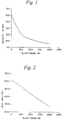
- the prior art time-based measurement concept is derived from the relationship of range being equal to velocity * time. As shown in Figure 1, for a typical 25mm projectile, tested at (15.5°C) 60°F and with a nominal muzzle velocity of 617 m/s, the velocity versus range is nonlinear. The curve shifts for different initial muzzle velocities, producing large errors in time-based range prediction.
- a turns counting fuze can measure actual muzzle velocity, as will be discussed more fully below, and provide a correction to the turns-to-burst count based on the difference between the nominal and actual muzzle velocity, so that by using down range turns counting it can produce minimal burst error.
- range determination can be based entirely on a turns count
- Alliant Techsystems has discovered that depending on specific ballistic application and range it may be more accurate to utilize both turns counting and time interval counting. For a given fixed muzzle velocity, Alliant Techsystems has discovered that turns performance is much better out to about 1000m. After this point, the velocity tends toward a terminal value and time performance is somewhat better.
- a fuze system may employ turns counting at the short and medium ranges, augmented by time prediction at far ranges.
- the fuze of the invention provides a unique approach to measure and correct for muzzle velocity.
- the same sensor that provides for setter communication measures spin rate at muzzle exit which is related to muzzle velocity by barrel twist, as is well known.
- This same sensor can be used to count turns down range, as the advance ratio is more accurate than time over a significant early portion of total range.
- the advance ratio equals the turns per unit distance of a projectile due to gun barrel rifling.
- the sensor allows for real time assessment of muzzle velocity and subsequent down range velocities. This sensor allows combining muzzle velocity, turns, and time to accurately establish a range dependant burst.
- the invention uses a magnetic circuit to communicate to the fuze.
- An inductive setting coil is driven by the fire control electronics with a receiving coil located in the fuze.
- the receiving coil is coupled to the setting coil by transformer action.
- Data is modulated onto a carrier signal.
- the carrier signal is rectified in the fuze and is used to charge a capacitor for storage of fuze system power.
- the modulation with mode, burst time, and other information is decoded and processed for operational parameter definition.
- the range to burst of a projectile is subject to errors due to various factors.
- the fire control electronics of a weapon system provide nominal data based on a calculated range to burst or time to burst to the fuze. This data is only as accurate as the projectile characteristics are close to the nominal settings, one of which is the nominal muzzle velocity. Therefore, it is desirable to adjust the range to burst based on actual measurement of the muzzle velocity.
- a sensor In order to determine muzzle velocity a sensor is employed to count the turns of the projectile. Full or partial turns may be counted, as desired.
- the sensor is a magnetic transducer which senses the earth's magnetic field.
- spin rate can be determined after a predetermined number of spins have been counted. Spin rate is proportional to muzzle velocity. In this manner, muzzle velocity is determined.
- the range to burst of the projectile may be adjusted to compensate for a muzzle velocity which is not equal to the nominal value. If the fuze is programmed to detonate after a number of counted turns, the calculated muzzle velocity is compared to the nominal velocity value and the number of turns to burst is adjusted upward or downward to compensate for any variation in velocity. If the measured muzzle velocity is greater than the nominal then the number of turns to burst is decreased to reduce error. If the measured velocity is less than the nominal then the number of turns to burst is increased to reduce error.
- the projectile 5 includes a base element 10, a warhead 12 and a nose element 14.
- the projectile 5 also contains a fuse 16 (shown in Figure 4) in the nose element 14 and/or the base element 10.
- the fuse may be "packaged” to fit in the nose element 14 and may also be “packaged” to fit in both the nose and base elements 14 and 10, as desired.
- Figure 4 shows the nose element 14 of Figure 3 with a fuze 16.
- Figure 4 shows the electronics 18 of the fuze 16 which are necessary for operation, which are well known in the art. In this preferred embodiment, two annular electronics portions are shown, as are well known in the art. This drawing is used to show an example of a fuze layout. Many other configurations of the fuze 16 are known and may be utilized within the spirit of the invention.
- the fuze 16 also includes a magnetic transducer 20.
- the magnetic transducer includes a single coil 22, a shaped core 24 and a magnet 26.
- This magnetic transducer 20 receives data from the remote setter (best seen in Figure 6) and also senses the earth's magnetic field to count turns of the projectile.
- the inherent axial sensitivity of the coil 22 acts as the receiver for the AC remote set communication waveform (best seen in Figure 8), introducing both power and data to the fuze.
- the cylindrical magnet portion 26 of the transducer 20 provides transformer coupling with the setter coil located in block 32 of Figure 6.
- the shape of the transducer core 24 establishes an output signal from coil 22 as the core 24 rotates around its longitudinal axis in an external homogeneous field.
- the tab-like portions 25 of the core causes magnetic flux to alternate in direction through the coil thereby producing a sine wave voltage.
- the sine wave voltage amplitude decreases with the cosine of the angle.
- the tabs 25 may be of different shape and size than shown, but still produce the alternating flux path as described herein. Further, the size of the transducer can be adjusted for rounds of different caliber.
- the core 24 gives the coil radial sensitivity, allowing monitoring of the earth's field as the projectile spins.
- the spin signal is in the form of a sine wave.
- One complete sine wave represents one turn of the projectile.
- a voltage is generated by the magnetic transducer 20 sensing the time-changing magnetic field of the earth due to projectile spin. The voltage amplitude increases until it peaks at a quarter turn of the projectile and then decreases to zero at the half turn point. The voltage then reverses direction and the amplitude increases to the three quarters turn point and then decreases to zero when one complete turn has been made. Therefore, the zero crossings can be counted.
- Each turn of the projectile is represented by two zero crossings.
- the spin signal allows for a determination of muzzle velocity as will be described below.
- the spin signal continues for the total life of the flight of the projectile and provides a means to accumulate a turns count as the basis for air burst prediction in place of, or in conjunction with a time prediction.
- a search coil magnetometer has been described herein, it should be understood that other magnetometers may be utilized.
- Block 30 represents the Fire Control System of a gun (not shown) which fires the projectile 5 including the fuzing system of the invention.
- the fire control system 30 is attached to or is an integral part of the gun and includes appropriate well known circuitry and processors for measuring the range to target of the projectile as desired by an operator.
- the fire control system 30 also computes the time to burst or turns to burst for the particular projectile based on the target selected by the operator and the known ballistic characteristics of the gun.
- Fire control systems are known in the art and provide numerous functions and information.
- the turns to burst count is derived from ballistic characteristics, other parameters and modeling which are known to those skilled in the art. Although derived in the past, the turns to burst count has not been utilized because no known method existed to count the turns of the projectile during flight.
- Block 32 represents the remote setter or fuze setter. This device is known in the art and provides for power-up of the fuze and also transmits the necessary information from the operator to the fuze.
- the fuze setter 32 is conductively connected to the fire control system 30 in the preferred embodiment.
- the remote setter 32 may be a remote unit hand held by the user or may be attached to the gun or an integral part of the gun.
- the fuze setter 32 accesses every round during the gun cycle to provide all communication functions to the fuze 10.
- the setter 32 is designed to allocate a period while the projectile is in the ram or pre-chamber position for communication. Each round receives the necessary exposure while the previous round is being fired.
- a typical setter 32 includes two coils (not shown) arranged so as to be closely coupled to the fuze nose element while the round is in the ram position.
- the coils are arranged to additively drive their leakage flux (flux outside the setter's coils) down the axis of the nose element 14 of the projectile 5 to the magnetic transducer 20.
- the setter 32 is inductively coupled to the fuze 10 of the projectile 5 and acts as a transmitter.
- the setter 32 must communicate information to the fuze 10. At a minimum, the information for a bursting round will contain a parameter representing range, i.e. turns to burst, time interval or a combination of both.
- the setter 32 may also pass information including mode settings and error compensation data. In this manner, a variety of functions or modes can be selected or prioritized individually in each round.
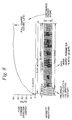
- the communication is shown in Figure 8 where the power-up and message period communicated to each fuze 16 from the setter 32 is depicted.
- the magnetic waveform received at the magnetic sensor 20 is a large peak to peak signal, in the preferred embodiment 40-50 volts in amplitude.
- the relatively high voltage allows for high energy storage on a capacitor 36 (shown in Figure 6) and is also used to charge another capacitor 38 (shown in Figure 6) in the base element specifically reserved for firing the detonator.
- the detonator capacitor 38 conserves fuze reliability in cases where the power storage capacitor 36 drains too low. By this means, all fuze electronic circuits are individually powered.
- Simultaneous with the storage of fuze power is the communication of calibration data and parameter data.
- An initial preamble of an accurate burst of 10 Khz is modulated at the beginning of the waveform to create a start signal, and is used in the fuze to quick-lock its own internal time base to the accurate 10kHz standard from the fire control electronics 30. Therefore, any algorithms or parameter measurements requiring accurate timing are available in the fuze electronics without an accurate internal time-base reference.
- frequency shift modulated signals of 7kHz or 13kHz referenced to the 10kHz which represent digital (bits) 1's and 0's.
- Up to twenty bits can be communicated to the fuse 16 in this message format to include data for burst, error compensation direction and mode settings, and time delays if desired. Eleven bits will allow parameter measurement to an accuracy greater than 0.1% and 9 bits remain for other functionality and future growth. It should be understood that the frequencies used for the preamble and to represent 1's and 0's, as well as the number of bits transmitted can be varied as desired.
- the magnetic transducer configuration 20 serves several functions and allows for several functions to be performed within the fuze 16 without specific on-axis positioning.
- the magnetic transducer 20 acts as a receiver where information is inductively communicated to the fuze 10.
- the power storage and supply 34 of the fuze is shown.
- the fuze 10 must have a power supply 34 to function.
- the inductive coupling of the transducer 20 to the fuze setter 32 allows large voltages to be transferred from the setter to the fuze 10, as discussed above. In this manner, the fuze 10 is powered.
- Block 40 represents the step of utilizing the fire control system 30 to measure target range. The time to burst or turns to burst or both are calculated based on nominal assumed gun and projectile parameters.
- Block 42 represents the step of communicating data including the range parameter of block 40 through the setter 32 to the transducer 20. This is done when the user operates the trigger, followed by insertion of the round into the chamber and firing the round.
- the fuze 16 includes communication circuitry 46. This circuitry 46 includes filtering networks 48 and bit decode and store capabilities 50 which decodes the parameters communicated to the fuze 16 and passes them to logic processor 62.
- the clock or timer 44 shown in Figure 6, is also calibrated.
- Fuze modes such as point detonate delay mode, air burst, standoff detonate, super quick point detonate, etc. which are well known, are also communicated to the fuze 16 at this point. Prioritization of fuze modes may also be communicated to the fuze 16.
- muzzle exit is detected. This function is represented by block 52 (shown in Figure 7).
- muzzle exit is determined using the transducer 20.
- the ferrous confinement in the gun barrel shields the transducer from the earth's magnetic field and upon exit an abrupt magnetic field transition is generated.
- the transducer senses this abrupt magnetic field transition and uses this sensing of muzzle exit as the starting point for the countdown to detonation.
- the time is set to zero and the turns count is set to zero. The count for time-to-burst, turns-to-burst or both is then started.
- the muzzle exit signal also serves as a true electronic second environment confirmation, as would be known by those skilled in the art.
- the signal starts a timer which determines a safe separation distance for the projectile.
- the spin rate is measured as represented by block 54.
- the spin rate is measured in the first few meters of travel.
- the number of turns must be counted.
- block 56 of the fuze 16 counts turns.
- the turns are sensed by the transducer 20 as described earlier.
- the signals are amplified and filtered 58 and the zero crossings are detected at 60 which drives logic 62 where the turns are counted.
- the time, time and/or turns to burst, and fuze mode are also input to the logic processor 62.
- C is a constant set by the barrel rifling (advance ratio).
- spin rate CV or the magnetometer measured spin signal is directly proportional to, and can be used to measure the actual muzzle velocity. In other words, knowing that the projectile will turn a predetermined number of times per unit distance, the number of turns over a measured time allows calculation of the actual muzzle velocity.
- block 64 represents the calculation of the muzzle velocity based on spin rate.
- the muzzle velocity is calculated by the logic processor 62.
- block 64 also adjusts the range parameter based on the muzzle velocity calculation. This function is performed by logic processor 62.
- the time-to-burst or turns-to-burst may be adjusted.
- the logic processor 62 includes look up tables or data which, based on the actual velocity, indicates the adjustment to the time or turns. This adjustment is designed for each gun/round combination and effectively compensates for the nonlinearity discussed above and shown in Figure 1. Such an adjustment could be implemented using a look-up table methodology based on test results and modeling.
- the table would be entered with the actual velocity and a corresponding turns correction number would be read out, where the correction number is based on the difference between the turns to burst for the nominal velocity and the turns to burst for the actual velocity.
- a more complicated version of the look-up table could incorporate different parameters such as angle of firing which is relevant to artillery guns and rounds and tank guns and rounds.
- Other projectile and gun parameters could easily be incorporated into a modified look-up table where the only limitations are the amount of memory (dictated by projectile size) available and the testing and modeling that is desired to be undertaken. As one skilled in the art knows, the amount of testing needed is limited by known modeling techniques.
- the final step is illustrated by block 66.
- the fuze initiates burst at proper range in block 66.
- the signal is transmitted from the logic processor 62 to the firing circuit 68.
- the firing circuit 68 is conductively connected to the detonator 70 for detonation of the projectile.
- the magnet 26 of the transducer 20 provides a short range armor proximity function for warhead standoff or hard/soft target differentiation by virtue of the target ferrous properties which forms a time varying magnetic circuit reluctance.
- the ferrous nature of a target such as a tank, initiates a distinct high frequency (dH/dt) signal which can be categorized as a short range proximity sensor.
- This signal is enhanced at short ranges by the permanent magnet "bias" field which is significantly stronger than either the targets induced or permanent signature. Therefore, a warhead may be predetonated at a short distance from the target or before target impact using this short range containment feature. An additional function is inherent from the standoff signal.
- the fuze can then, in effect, differentiate between a heavy ferrous target and lighter composite or non-metallic targets such as a bunker.
- the heavy ferrous target is categorized as hard and the light composite target as soft.
- short standoff (shaped charge) warhead detonation is desired for hard targets and a delayed detonation after impact is desired for soft targets.
- the impact sensor 72 is used to cause the projectile to detonate if it impacts a target prior to the generation of a "hard target" detonation signal by the electronics in fuze 16.
- a piezo crystal is utilized for this function. This function is commonly referred to as the point detonate function.
- Another means for accomplishing this non-hard target impact function is the use of a flyer disk 80 (shown in Figure 4). The thin flyer disk is held to the front of the transducer magnet. Upon impact, this disk would inertially release and by magnetic physics effects produce an easily recognizable (dH/dt) signal. Yet another approach is with the magnet itself.
- the magnet can be designed, by its composition, to change magnetization at the shock level of impact, thereby producing an appropriate signal. All of these impact sensor functions can be used in combination with the timer to achieve delay point detonation. The specific electronics and designs to achieve these functions are well known in the art.
Landscapes
- Engineering & Computer Science (AREA)
- General Engineering & Computer Science (AREA)
- Aiming, Guidance, Guns With A Light Source, Armor, Camouflage, And Targets (AREA)
- Soft Magnetic Materials (AREA)
- Measurement Of Unknown Time Intervals (AREA)
- Measurement Of Length, Angles, Or The Like Using Electric Or Magnetic Means (AREA)
Description
- This invention relates to the field of fuzes and more particularly, to an apparatus and method for control of a projectile with fuze functions including magnetically sensing ballistic spin parameters and computing muzzle velocity for accurately controlling range to burst of a projectile.
- Remote settable fuzes have been used in projectiles for some time. A remote settable fuze allows external information to be input to the projectile before firing. One known method for inputing information to the fuze is by non-contact inductive coupling. This is a transformer approach with the primary of the transformer placed outside the projectile, in what is commonly called a setter, and the secondary of the transformer placed in the fuze. Magnetic flux passes between the primary and secondary with appropriate AC modulation containing data. The information input to the fuze relates to a fuze mode setting or for example, may contain a time-to-burst for the projectile. Time-to-burst represents a predetermined time period after firing, approximating a desired range, after which the projectile detonates.
- Another apparatus for measuring the distance travelled by a moving body such as a projectile or missile is disclosed in the patent specification GB-A-1 129 448 which disclosure accords with the preamble of claims 1 and 15. There is provided equipment for measuring the distance travelled by said projectile by counting revolutions of said projectile in the earths magnetic field. A transducer having a pick-up coil wound on a core of magnetic permeable material is rotating in the earths magnetic field with said profile and providing electrical signals corresponding to the number of revolutions of said projectile which are submitted to a counter which is responsive to said electrical signals. To utilize this equipment as applied to an artillery projectile it is necessary to know the pitch of the helix traced by a point on the projectile's surface during flight. The relationship Distance=Number of Revolutions x Pitch determines the point of detonation.
- In a bursting munitions scenario. the most important features of the projectile and its fuze are accuracy and safety to the user. These factors are related to fuze control functions. Previously, systems have used expensive and complicated mechanical and/or electrical methods to try to more accurately determine the range of a projectile and control the fuze. One variable which greatly affects the accuracy of the range determination is the actual muzzle velocity, which can vary depending on a large number of known factors. It has always been desirable to control the detonation of a projectile based on a determination of actual muzzle velocity. However, an accurate system for determining muzzle velocity within a projectile has not been available. Systems mounted directly on the muzzle of specialized guns do exist, but greatly complicate the gun and are contrary to a general standardized approach for all weapons.
- Prior systems have depended on time setting and have not been able to accurately predict muzzle velocity. Other fuzing systems require mechanical settings by the user for communicating functions. This dependency on the operator creates a much larger risk of mistake or accident. Other electronic systems have proved to be too costly and require more space in the projectile than is available. Also, some prior solutions use parts, such as crystals, which cannot readily tolerate the forces or shock which the projectile experiences.
- Consequently, a need remains for a compact, simple multifunctional sensor that acts as a remote receiver and provides more accurate detonation of the projectile.
- This invention is a sensor for a class of projectile fuzes for use in artillery rounds, tank rounds, medium caliber bullets of all sizes, and individually carried combat weapons. The functions inherent in this fuze include those required by present standards and further include several other functions not available with prior art fuzes and are all accomplished with a single magnetic sensor element. In particular, internal turns counting is provided so that a turns-to-burst detonation mode is possible. The revolutions per second or turns of the projectile are counted and the detonation of the projectile is based on this count. Another related function of the invention is the determination of muzzle velocity based on turns counting, which allows for calculation of what has always been an indeterminate measurement. The determination of muzzle velocity allows for compensation of the fire control systems' count estimate of the turns-to-burst, which is based on a nominal assumed muzzle velocity, by modifying the turns-to-burst count based on the actual muzzle velocity measurement.
- The inventive sensor therefore functions as a remote set receiver, a ballistic turns counter and a muzzle velocity calculator. The present invention eliminates the previously mentioned problems and provides a single sensor internal to the fuze to power the fuze, accurately sense remote settings and modes, provide a count of ballistic turns to determine muzzle velocity, and provide a multitude of functions which lead to accurate and safe deployment of projectiles. The fuze can use the measurement of the actual muzzle velocity to compensate the turns-to-burst count for deviations of the actual muzzle velocity from the assumed nominal muzzle velocity.
- The invention comprises an apparatus for counting each rotation of a projectile, after firing the projectile from a firing weapon, the projectile having a longitudinal axis, the apparatus comprising counting means for counting each rotation of the projectile as it rotates around its longitudinal axis. The counting means further includes spin signal means for generating a spin signal which varies over tune as the projectile rotates about its axis in the earth's magnetic field and where the magnitude of the spin signal reaches a predetermined threshold a predetermined number of times for each rotation of the projectile and a counter operatively connected to the spin signal means for counting the number of times the spin signal reaches its predetermined threshold.
-
- Figure 1 is a graph illustrating the velocity profile of a 25mm projectile over a range;
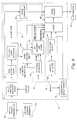
- Figure 2 is a graph illustrating the spin profile of a 25mm projectile over a range;
- Figure 3 is a cross section of a projectile which utilizes the invention;
- Figure 4 is a cross section of the nose element of a projectile showing the nose fuze components of the invention;
- Figure 5 is a perspective view of the magnetic transducer of the invention:
- Figure 6 is a block diagram of the invention;
- Figure 7 is a block diagram of the algorithm for determining muzzle velocity; and
- Figure 8 is a graph illustrating the power up and message period for the invention.
-
- While this invention may be embodied in many different forms, there are described in detail herein specific preferred embodiments of the invention. This description is an exemplification of the principles of the invention and is not intended to limit the invention to the particular embodiments illustrated.
- The bursting munition fuze can be categorized as the "remote control" element of a weapons system. Once the projectile leaves the gun, the fuze is the last control on the projectile's functions. Therefore, the fuze is a vital performance link between the initial optimized attributes of the gun and fire control subsystems and the ultimate maximization of the warhead effects. As is well known, the fire control subsystem measures target range, cant, wind, temperature, pressure, and target motion and predicts a gun setting and subsequently communicates a burst range prediction to the fuze based on calculated ballistic parameters.
- The ultimate effectiveness of the weapon is directly related to control of errors for the air burst prediction. A commonly employed approach is to convert the target range (from the fire control rangefinder) into a time countdown number based on estimated projectile ballistics. One of the important ballistic characteristics is the nominal muzzle velocity for a particular projectile and gun. A more accurate ballistic prediction could be provided by basing the time countdown on an actual muzzle velocity rather than relying solely on the nominal or assumed muzzle velocity for that class of projectile and gun. The actual muzzle velocity changes with propellant load, propellant density, propellant temperature, and barrel wear and can result in range errors on the order of one hundred meters, when using the nominal muzzle velocity parameter. This range error is unacceptable.
- A fuze cannot measure range directly and therefore uses a parameter proportional to range. The prior art time-based measurement concept is derived from the relationship of range being equal to velocity * time. As shown in Figure 1, for a typical 25mm projectile, tested at (15.5°C) 60°F and with a nominal muzzle velocity of 617 m/s, the velocity versus range is nonlinear. The curve shifts for different initial muzzle velocities, producing large errors in time-based range prediction.
- Alliant Techsystems has discovered analytically and experimentally that a turns counting base parameter behaves more ideally (more linear) as shown in Figure 2, which was tested at (15.5°C) 60°F and with a 6° gun twist. As will be discussed more fully below, Alliant Techsystems has discovered that they can use the earth's magnetic field to count the turns of the projectile. From the known gun characteristics and the turns count, the instantaneous spin rate of the projectile can be calculated. The spin profile (spin versus range) shown in Figure 2 is for a 25mm projectile and is relatively linear and predictable, producing better prediction performance than time interval measurement. Instantaneous spin rate is an excellent base parameter estimator of a projectile's velocity over a good part of its flight and especially near the muzzle. A turns counting fuze can measure actual muzzle velocity, as will be discussed more fully below, and provide a correction to the turns-to-burst count based on the difference between the nominal and actual muzzle velocity, so that by using down range turns counting it can produce minimal burst error. Although the range determination can be based entirely on a turns count, Alliant Techsystems has discovered that depending on specific ballistic application and range it may be more accurate to utilize both turns counting and time interval counting. For a given fixed muzzle velocity, Alliant Techsystems has discovered that turns performance is much better out to about 1000m. After this point, the velocity tends toward a terminal value and time performance is somewhat better. Therefore, it is optimal to utilize a fuse having a sensor which continuously measures turns and an algorithm to measure velocity based on turns counting in conjunction with time interval counting. In this manner, a fuze system may employ turns counting at the short and medium ranges, augmented by time prediction at far ranges.
- The fuze of the invention provides a unique approach to measure and correct for muzzle velocity. The same sensor that provides for setter communication measures spin rate at muzzle exit which is related to muzzle velocity by barrel twist, as is well known. This same sensor can be used to count turns down range, as the advance ratio is more accurate than time over a significant early portion of total range. The advance ratio equals the turns per unit distance of a projectile due to gun barrel rifling. The sensor allows for real time assessment of muzzle velocity and subsequent down range velocities. This sensor allows combining muzzle velocity, turns, and time to accurately establish a range dependant burst.
- The invention uses a magnetic circuit to communicate to the fuze. An inductive setting coil is driven by the fire control electronics with a receiving coil located in the fuze. The receiving coil is coupled to the setting coil by transformer action. Data is modulated onto a carrier signal. The carrier signal is rectified in the fuze and is used to charge a capacitor for storage of fuze system power. The modulation with mode, burst time, and other information is decoded and processed for operational parameter definition.
- As described above, the range to burst of a projectile is subject to errors due to various factors. The fire control electronics of a weapon system provide nominal data based on a calculated range to burst or time to burst to the fuze. This data is only as accurate as the projectile characteristics are close to the nominal settings, one of which is the nominal muzzle velocity. Therefore, it is desirable to adjust the range to burst based on actual measurement of the muzzle velocity.
- In order to determine muzzle velocity a sensor is employed to count the turns of the projectile. Full or partial turns may be counted, as desired. The sensor is a magnetic transducer which senses the earth's magnetic field. As will be discussed more fully below, based on the characteristics of the gun, spin rate can be determined after a predetermined number of spins have been counted. Spin rate is proportional to muzzle velocity. In this manner, muzzle velocity is determined.
- Once muzzle velocity has been determined, the range to burst of the projectile may be adjusted to compensate for a muzzle velocity which is not equal to the nominal value. If the fuze is programmed to detonate after a number of counted turns, the calculated muzzle velocity is compared to the nominal velocity value and the number of turns to burst is adjusted upward or downward to compensate for any variation in velocity. If the measured muzzle velocity is greater than the nominal then the number of turns to burst is decreased to reduce error. If the measured velocity is less than the nominal then the number of turns to burst is increased to reduce error.
- Referring to Figure 3, a cross section of a
projectile 5 is shown. Theprojectile 5 includes abase element 10, awarhead 12 and anose element 14. The projectile 5 also contains a fuse 16 (shown in Figure 4) in thenose element 14 and/or thebase element 10. One skilled in the art knows that the fuse may be "packaged" to fit in thenose element 14 and may also be "packaged" to fit in both the nose andbase elements - Figure 4 shows the
nose element 14 of Figure 3 with afuze 16. Figure 4 shows theelectronics 18 of thefuze 16 which are necessary for operation, which are well known in the art. In this preferred embodiment, two annular electronics portions are shown, as are well known in the art. This drawing is used to show an example of a fuze layout. Many other configurations of thefuze 16 are known and may be utilized within the spirit of the invention. - Referring to Figure 5, the
fuze 16 also includes amagnetic transducer 20. The magnetic transducer includes asingle coil 22, a shapedcore 24 and amagnet 26. Thismagnetic transducer 20 receives data from the remote setter (best seen in Figure 6) and also senses the earth's magnetic field to count turns of the projectile. The inherent axial sensitivity of thecoil 22 acts as the receiver for the AC remote set communication waveform (best seen in Figure 8), introducing both power and data to the fuze. Thecylindrical magnet portion 26 of thetransducer 20 provides transformer coupling with the setter coil located inblock 32 of Figure 6. - The shape of the
transducer core 24 establishes an output signal fromcoil 22 as thecore 24 rotates around its longitudinal axis in an external homogeneous field. When the earth's magnetic field is perpendicular to the spin axis (radial field), the tab-like portions 25 of the core causes magnetic flux to alternate in direction through the coil thereby producing a sine wave voltage. As the alignment angle between the spin axis and the earth's field vector direction changes, the sine wave voltage amplitude decreases with the cosine of the angle. One skilled in the art will recognize that thetabs 25 may be of different shape and size than shown, but still produce the alternating flux path as described herein. Further, the size of the transducer can be adjusted for rounds of different caliber. - The
core 24 gives the coil radial sensitivity, allowing monitoring of the earth's field as the projectile spins. The spin signal is in the form of a sine wave. One complete sine wave represents one turn of the projectile. A voltage is generated by themagnetic transducer 20 sensing the time-changing magnetic field of the earth due to projectile spin. The voltage amplitude increases until it peaks at a quarter turn of the projectile and then decreases to zero at the half turn point. The voltage then reverses direction and the amplitude increases to the three quarters turn point and then decreases to zero when one complete turn has been made. Therefore, the zero crossings can be counted. Each turn of the projectile is represented by two zero crossings. One skilled in the art will recognize that known engineering methods may be utilized to count partial turns of the projectile so that the turns count may count quarters of a turn or a partial turn. The spin signal allows for a determination of muzzle velocity as will be described below. The spin signal continues for the total life of the flight of the projectile and provides a means to accumulate a turns count as the basis for air burst prediction in place of, or in conjunction with a time prediction. Although a search coil magnetometer has been described herein, it should be understood that other magnetometers may be utilized. - Referring to Figure 6, a block diagram of a weapons system including the invention is shown.
Block 30 represents the Fire Control System of a gun (not shown) which fires the projectile 5 including the fuzing system of the invention. Thefire control system 30 is attached to or is an integral part of the gun and includes appropriate well known circuitry and processors for measuring the range to target of the projectile as desired by an operator. Thefire control system 30 also computes the time to burst or turns to burst for the particular projectile based on the target selected by the operator and the known ballistic characteristics of the gun. Fire control systems are known in the art and provide numerous functions and information. The turns to burst count is derived from ballistic characteristics, other parameters and modeling which are known to those skilled in the art. Although derived in the past, the turns to burst count has not been utilized because no known method existed to count the turns of the projectile during flight. The above are provided as examples to explain the invention and should not be considered as limitations of the invention. -
Block 32 represents the remote setter or fuze setter. This device is known in the art and provides for power-up of the fuze and also transmits the necessary information from the operator to the fuze. Thefuze setter 32 is conductively connected to thefire control system 30 in the preferred embodiment. Theremote setter 32 may be a remote unit hand held by the user or may be attached to the gun or an integral part of the gun. Thefuze setter 32 accesses every round during the gun cycle to provide all communication functions to thefuze 10. Thesetter 32 is designed to allocate a period while the projectile is in the ram or pre-chamber position for communication. Each round receives the necessary exposure while the previous round is being fired. - A
typical setter 32 includes two coils (not shown) arranged so as to be closely coupled to the fuze nose element while the round is in the ram position. The coils are arranged to additively drive their leakage flux (flux outside the setter's coils) down the axis of thenose element 14 of the projectile 5 to themagnetic transducer 20. Thesetter 32 is inductively coupled to thefuze 10 of theprojectile 5 and acts as a transmitter. Thesetter 32 must communicate information to thefuze 10. At a minimum, the information for a bursting round will contain a parameter representing range, i.e. turns to burst, time interval or a combination of both. Thesetter 32 may also pass information including mode settings and error compensation data. In this manner, a variety of functions or modes can be selected or prioritized individually in each round. - The communication is shown in Figure 8 where the power-up and message period communicated to each
fuze 16 from thesetter 32 is depicted. The magnetic waveform received at themagnetic sensor 20 is a large peak to peak signal, in the preferred embodiment 40-50 volts in amplitude. The relatively high voltage allows for high energy storage on a capacitor 36 (shown in Figure 6) and is also used to charge another capacitor 38 (shown in Figure 6) in the base element specifically reserved for firing the detonator. Thedetonator capacitor 38 conserves fuze reliability in cases where thepower storage capacitor 36 drains too low. By this means, all fuze electronic circuits are individually powered. - Simultaneous with the storage of fuze power is the communication of calibration data and parameter data. An initial preamble of an accurate burst of 10 Khz is modulated at the beginning of the waveform to create a start signal, and is used in the fuze to quick-lock its own internal time base to the accurate 10kHz standard from the
fire control electronics 30. Therefore, any algorithms or parameter measurements requiring accurate timing are available in the fuze electronics without an accurate internal time-base reference. - Following the 10kHz preamble are frequency shift modulated signals of 7kHz or 13kHz referenced to the 10kHz which represent digital (bits) 1's and 0's. Up to twenty bits can be communicated to the
fuse 16 in this message format to include data for burst, error compensation direction and mode settings, and time delays if desired. Eleven bits will allow parameter measurement to an accuracy greater than 0.1% and 9 bits remain for other functionality and future growth. It should be understood that the frequencies used for the preamble and to represent 1's and 0's, as well as the number of bits transmitted can be varied as desired. - The
magnetic transducer configuration 20 serves several functions and allows for several functions to be performed within thefuze 16 without specific on-axis positioning. Themagnetic transducer 20 acts as a receiver where information is inductively communicated to thefuze 10. Referring again to Figure 6, the power storage andsupply 34 of the fuze is shown. Thefuze 10 must have apower supply 34 to function. The inductive coupling of thetransducer 20 to thefuze setter 32 allows large voltages to be transferred from the setter to thefuze 10, as discussed above. In this manner, thefuze 10 is powered. - Referring to Figure 7, a top level algorithm of the invention is depicted. Figures 7 and 6 will be discussed in tandem.
Block 40 represents the step of utilizing thefire control system 30 to measure target range. The time to burst or turns to burst or both are calculated based on nominal assumed gun and projectile parameters.Block 42 represents the step of communicating data including the range parameter ofblock 40 through thesetter 32 to thetransducer 20. This is done when the user operates the trigger, followed by insertion of the round into the chamber and firing the round. Thefuze 16 includescommunication circuitry 46. Thiscircuitry 46 includesfiltering networks 48 and bit decode andstore capabilities 50 which decodes the parameters communicated to thefuze 16 and passes them tologic processor 62. The clock ortimer 44, shown in Figure 6, is also calibrated. Fuze modes, such as point detonate delay mode, air burst, standoff detonate, super quick point detonate, etc. which are well known, are also communicated to thefuze 16 at this point. Prioritization of fuze modes may also be communicated to thefuze 16. - Once data has been communicated to the
fuze 16, muzzle exit is detected. This function is represented by block 52 (shown in Figure 7). As discussed above, muzzle exit is determined using thetransducer 20. The ferrous confinement in the gun barrel shields the transducer from the earth's magnetic field and upon exit an abrupt magnetic field transition is generated. The transducer senses this abrupt magnetic field transition and uses this sensing of muzzle exit as the starting point for the countdown to detonation. In other words, at muzzle exit, the time is set to zero and the turns count is set to zero. The count for time-to-burst, turns-to-burst or both is then started. - The muzzle exit signal also serves as a true electronic second environment confirmation, as would be known by those skilled in the art. The signal starts a timer which determines a safe separation distance for the projectile.
- After muzzle exit has been determined, the spin rate is measured as represented by
block 54. The spin rate is measured in the first few meters of travel. In order to measure spin rate the number of turns must be counted. Referring now to Figure 6, block 56 of thefuze 16 counts turns. The turns are sensed by thetransducer 20 as described earlier. The signals are amplified and filtered 58 and the zero crossings are detected at 60 which driveslogic 62 where the turns are counted. The time, time and/or turns to burst, and fuze mode are also input to thelogic processor 62. - The ballistic spin relationship is as follows:
- C is a constant set by the barrel rifling (advance ratio).However,

- Therefore, spin rate = CV or the magnetometer measured spin signal is directly proportional to, and can be used to measure the actual muzzle velocity. In other words, knowing that the projectile will turn a predetermined number of times per unit distance, the number of turns over a measured time allows calculation of the actual muzzle velocity.
- Referring again to Figure 7, block 64 represents the calculation of the muzzle velocity based on spin rate. The muzzle velocity is calculated by the
logic processor 62. At this point, block 64 also adjusts the range parameter based on the muzzle velocity calculation. This function is performed bylogic processor 62. The time-to-burst or turns-to-burst may be adjusted. Thelogic processor 62 includes look up tables or data which, based on the actual velocity, indicates the adjustment to the time or turns. This adjustment is designed for each gun/round combination and effectively compensates for the nonlinearity discussed above and shown in Figure 1. Such an adjustment could be implemented using a look-up table methodology based on test results and modeling. In its most simple form, the table would be entered with the actual velocity and a corresponding turns correction number would be read out, where the correction number is based on the difference between the turns to burst for the nominal velocity and the turns to burst for the actual velocity. A more complicated version of the look-up table could incorporate different parameters such as angle of firing which is relevant to artillery guns and rounds and tank guns and rounds. Other projectile and gun parameters could easily be incorporated into a modified look-up table where the only limitations are the amount of memory (dictated by projectile size) available and the testing and modeling that is desired to be undertaken. As one skilled in the art knows, the amount of testing needed is limited by known modeling techniques. - The final step is illustrated by
block 66. The fuze initiates burst at proper range inblock 66. The signal is transmitted from thelogic processor 62 to thefiring circuit 68. The firingcircuit 68 is conductively connected to thedetonator 70 for detonation of the projectile. - The
magnet 26 of the transducer 20 (best seen in Figure 6) provides a short range armor proximity function for warhead standoff or hard/soft target differentiation by virtue of the target ferrous properties which forms a time varying magnetic circuit reluctance. The ferrous nature of a target, such as a tank, initiates a distinct high frequency (dH/dt) signal which can be categorized as a short range proximity sensor. This signal is enhanced at short ranges by the permanent magnet "bias" field which is significantly stronger than either the targets induced or permanent signature. Therefore, a warhead may be predetonated at a short distance from the target or before target impact using this short range containment feature. An additional function is inherent from the standoff signal. If no short standoff signal has occurred just prior to impact, the fuze can then, in effect, differentiate between a heavy ferrous target and lighter composite or non-metallic targets such as a bunker. The heavy ferrous target is categorized as hard and the light composite target as soft. In general, short standoff (shaped charge) warhead detonation is desired for hard targets and a delayed detonation after impact is desired for soft targets. - The
impact sensor 72 is used to cause the projectile to detonate if it impacts a target prior to the generation of a "hard target" detonation signal by the electronics infuze 16. In a preferred embodiment, a piezo crystal is utilized for this function. This function is commonly referred to as the point detonate function. Another means for accomplishing this non-hard target impact function is the use of a flyer disk 80 (shown in Figure 4). The thin flyer disk is held to the front of the transducer magnet. Upon impact, this disk would inertially release and by magnetic physics effects produce an easily recognizable (dH/dt) signal. Yet another approach is with the magnet itself. The magnet can be designed, by its composition, to change magnetization at the shock level of impact, thereby producing an appropriate signal. All of these impact sensor functions can be used in combination with the timer to achieve delay point detonation. The specific electronics and designs to achieve these functions are well known in the art. - One skilled in the art would also realize that a combination of turns only, time only, turns then time, or time then turns modes of operation could be easily implemented using the inventive fuze. The time function may also be utilized for a self destruct mode.
- The above Examples and disclosure are intended to be illustrative and not exhaustive. These examples and description will suggest many variations and alternatives to one of ordinary skill in this art. All these alternatives and variations are intended to be included within the scope of the attached claims. Those familiar with the art may recognize other equivalents to the specific embodiments described herein which equivalents are also intended to be encompassed by the claims attached hereto.
Claims (15)
- Multifunctional magnetic fuse apparatus in a weapons system for determining the detonation point of a projectile fired from a gun where the projectile (5) spins about its longitudinal axis with magnetic transducer means (20) for use with a fuse (16) of the projectile (5), comprising:(a) means (32) for setting a turns-to-burst turns count in the fuse (16);(b) means (62) for counting each rotation of the projectile as it rotates around its longitudinal axis in the earth's magnetic field; and(c) means (70) for detonating the projectile (5) when the turns-to-burst turn count has been reached;characterized in thatsaid magnetic transducer means (20) generating a spin signal which varies over time as the projectile (5) rotates about its axis in the earth's magnetic field; and wherein the turns of the projectile (5) are counted by counting the number of times said spin signal reaches its predetermined threshold;prior to firing the projectile (5), the magnetic transducer means (20) receives setting parameters from an inductive transmitter (32);said magnetic transducer means (20) senses the abrupt magnetic field transition upon muzzle exit, and the resulting inductive signal is used as the starting point for the countdown to detonation;spin rate computation means (54) determine the spin rate of the projectile (5) by counting the number of turns whereas a timer (44) determines the time for the projectile (5) to rotate a predetermined number of times; andmuzzle velocity computing means (64) determine the actual muzzle velocity based on a barrel pitch constant of the firing gun and the spin rate of the projectile.
- The apparatus of claim 1, characterized in that said spin signal is sinusoidal and the predetermined threshold magnitude is zero, and where the zero threshold is crossed twice for each complete rotation of the projectile whereby each complete rotation generates one wavelength of the sinusoidal spin signal.
- The apparatus of claim 1, characterized in that the said transducer means (20) comprises a magnet (26), a conductive winding coil (22) and a core (24, 25) through which the earth's magnetic field generates a time varying signal as the projectile (5) rotates.
- The apparatus of claim 1, characterized in that said transducer means (20) is inductively receiving a turns-to-burst range parameter prior to the projectile (5) exiting the gun, wherein said parameter is based in part on a nominal muzzle velocity parameter, and where the detonation means (70) is activated when the counter (62) indicates that the projectile (5) has rotated a number of times equal to the turns-to-burst range parameter.
- The apparatus of claim 4, characterized by adjusting the turns-to-burst range parameter with the actual muzzle velocity calculated on the basis of a barrel pitch constant of the gun and the spin rate of the projectile, and where the detonation means (70) detonates the projectile (5) when it has reached the adjusted turns-to-burst range parameter, whereby the accuracy of the detonation is increased.
- The apparatus of claim 5, wherein a time interval range parameter is received by said transducer means (20) in addition to the turns-to-burst range parameter, and wherein the projectile (5) utilizes spin rate counting over a first predetermined portion of the projectile trajectory and the time interval based on the adjusted turns-to-burst range parameter over a second predetermined portion of the projectile trajectory.
- The apparatus of claim 6, characterized in that the projectile (5) utilizes the counter (62) for the first 1.000 meters and utilizes the time interval thereafter until projectile detonation.
- The apparatus of claim 1, characterized in that after determination of the actual muzzle velocity by said computing means (64) the turns count is adjusted, based in part on a nominal assumed muzzle velocity for the difference between the nominal assumed muzzle velocity and the actual muzzle velocity.
- The apparatus of claim 6, characterized by an interval timer (44) for storing the time interval range parameter, and that said time interval range parameter is decremented to zero whereupon the detonation means (70) detonates the projectile (5).
- The apparatus of claim 1, characterized by a power supply (34) including a capacitor (36, 38) operatively connected to said transducer means (20), which capacitor is charged when the projectile (5) receives a data carrying signal which is used to provide power for the fuze after firing.
- The apparatus of claim 1, characterized by a proximity sensor (72) for sensing ferrous objects a predetermined distance from the projectile (5) operatively connected to the detonation means (70) for detonating the projectile (5) regardless of whether the turns-to-burst count has been reached.
- The apparatus of claim 1, characterized by an impact sensor (72) operatively connected to the detonation means (70) for detonating the projectile at impact with a target regardless of whether the the turns-to-burst count has been reached.
- The apparatus of claim 12, characterized by delay means operatively connected to said detonation means (70) for delaying the detonation of the projectile (5) for a predetermined time period.
- The apparatus of claim 12, characterized by ferrous detection means incorporated in said impact sensor (72) for differentiating between a target which is substantially ferrous and a target which is substantially non-ferrous, operatively connected to said detonation means (70) wherein the projectile (5) detonates on impact if a substantially ferrous target is detected and detonates after a predetermined delay if a substantially non-ferrous target is detected.
- Method for determining the muzzle velocity of a projectile (5), after firing the projectile from a gun, wherein each rotation of the projectile is counted as it rotates around its longitudinal axis, characterized by the following steps:(a) when counting each rotation, a spin signal is generated which varies over time as the projectile rotates about its longitudinal axis in the earth's magnetic field and where the spin signal reaches a predetermined threshold a predetermined number of times for each rotation of the projectile, whereby a rotation is counted when the spin signal reaches its threshold the predetermined number of times;(b) a spin rate of the projectile is calculated (54) by timing the time for the projectile to rotate a predetermined number of times; and(c) a muzzle velocity is calculated (64) based ona barrel pitch constant of the gun, andthe spin rate of the projectile.
Applications Claiming Priority (2)
| Application Number | Priority Date | Filing Date | Title |
|---|---|---|---|
| US08/176,355 US5497704A (en) | 1993-12-30 | 1993-12-30 | Multifunctional magnetic fuze |
| US176355 | 1998-10-21 |
Publications (2)
| Publication Number | Publication Date |
|---|---|
| EP0661516A1 EP0661516A1 (en) | 1995-07-05 |
| EP0661516B1 true EP0661516B1 (en) | 1999-02-10 |
Family
ID=22644017
Family Applications (1)
| Application Number | Title | Priority Date | Filing Date |
|---|---|---|---|
| EP94120899A Expired - Lifetime EP0661516B1 (en) | 1993-12-30 | 1994-12-29 | Multifunctional magnetic fuze |
Country Status (7)
| Country | Link |
|---|---|
| US (1) | US5497704A (en) |
| EP (1) | EP0661516B1 (en) |
| CA (1) | CA2139291C (en) |
| DE (1) | DE69416503T2 (en) |
| ES (1) | ES2127342T3 (en) |
| NO (1) | NO310381B1 (en) |
| SG (1) | SG47776A1 (en) |
Cited By (1)
| Publication number | Priority date | Publication date | Assignee | Title |
|---|---|---|---|---|
| EP1742233A2 (en) | 2005-07-07 | 2007-01-10 | Rheinmetall Waffe Munition GmbH | Receiver coil for a programmable projectile fuse |
Families Citing this family (61)
| Publication number | Priority date | Publication date | Assignee | Title |
|---|---|---|---|---|
| DE59608912D1 (en) * | 1995-09-28 | 2002-04-25 | Contraves Pyrotec Ag | Method and device for programming projectile timers |
| US5705766A (en) * | 1995-10-30 | 1998-01-06 | Motorola, Inc. | Electronic turns-counting fuze and method therefor |
| NO312143B1 (en) * | 1996-04-19 | 2002-03-25 | Contraves Ag | Procedure for determining the desired split time, especially for a programmable projectile |
| NO311954B1 (en) * | 1996-04-19 | 2002-02-18 | Contraves Ag | Procedure for determining a programmable projectile breakdown time |
| NO311953B1 (en) * | 1996-04-19 | 2002-02-18 | Contraves Ag | Method and apparatus for determining the time of division of a programmable projectile |
| FR2770637B1 (en) * | 1997-11-03 | 1999-12-03 | Giat Ind Sa | PROJECTILE WITH SHAPED LOAD AND WEAPON SYSTEM HAVING SUCH A PROJECTILE |
| US6151563A (en) * | 1998-01-14 | 2000-11-21 | Silicon Pie, Inc. | Speed, spin rate, and curve measuring device using magnetic field sensors |
| US20020073869A1 (en) * | 1998-03-11 | 2002-06-20 | Tiernan Timothy C. | Ultra sensitive magnetic field sensors |
| US6295931B1 (en) * | 1998-03-11 | 2001-10-02 | Tpl, Inc. | Integrated magnetic field sensors for fuzes |
| US6196130B1 (en) | 1998-09-22 | 2001-03-06 | Alliant Techsystems Inc. | Electrostatic arming apparatus for an explosive projectile |
| EP0992761B1 (en) | 1998-10-08 | 2002-11-13 | Oerlikon Contraves Pyrotec AG | Method for correcting the preprogrammed triggering of a process in a spin-stabilized projectile, device for carrying out said method and use of this device |
| DE59914323D1 (en) * | 1998-10-08 | 2007-06-14 | Contraves Ag | Method and device for correcting the breaking time or the breaking speed of a spin-stabilized programmable projectile |
| DE59900920D1 (en) * | 1998-10-08 | 2002-04-11 | Contraves Ag | Method and device for transferring information to programmable projectiles |
| US6163021A (en) * | 1998-12-15 | 2000-12-19 | Rockwell Collins, Inc. | Navigation system for spinning projectiles |
| US6433533B1 (en) * | 1999-03-03 | 2002-08-13 | Sardis Technologies Llc | Giant magneto-impedance(GMI) spin rate sensor |
| US6176168B1 (en) * | 1999-04-29 | 2001-01-23 | Alliant Techsystems Inc. | Transmitter coil, improved fuze setter circuitry for adaptively tuning the fuze setter circuit for resonance and current difference circuitry for interpreting a fuze talkback message |
| DE19941301C1 (en) * | 1999-08-31 | 2000-12-07 | Honeywell Ag | Electronic timed shell detonator has timing program for electronic control unit initiated only after closure of switch via mechanical safety device |
| AUPQ524000A0 (en) * | 2000-01-24 | 2000-06-15 | Metal Storm Limited | Anti-missile missiles |
| US6345785B1 (en) * | 2000-01-28 | 2002-02-12 | The United States Of America As Represented By The Secretary Of The Army | Drag-brake deployment method and apparatus for range error correction of spinning, gun-launched artillery projectiles |
| DE10004582C1 (en) * | 2000-02-02 | 2001-08-30 | Honeywell Ag | Electronic projectile detonator |
| US7004072B1 (en) | 2000-03-30 | 2006-02-28 | Alliant Techsystems Inc. | Magnetically sensed second environment safety and arming device |
| DE10129043A1 (en) * | 2001-06-15 | 2003-01-02 | Diehl Munitionssysteme Gmbh | Methods and devices for determining the triggering of a braking device for the target-specific correction of the ballistic trajectory of a projectile |
| US6557450B1 (en) * | 2002-02-13 | 2003-05-06 | The United States Of America As Represented By The Secretary Of The Navy | Power indicating setter system for inductively-fuzed munitions |
| US6592070B1 (en) * | 2002-04-17 | 2003-07-15 | Rockwell Collins, Inc. | Interference-aided navigation system for rotating vehicles |
| AU2002950846A0 (en) * | 2002-08-16 | 2002-09-12 | Metal Storm Limited | Interception missile and method of interception |
| US7299734B2 (en) * | 2003-08-20 | 2007-11-27 | Craig L Holloway | Synchronously/synergeticly timed fuse procedure or process |
| US7077045B2 (en) * | 2003-09-24 | 2006-07-18 | Raytheon Company | Projectile inductive interface for the concurrent transfer of data and power |
| US20050126379A1 (en) * | 2003-12-10 | 2005-06-16 | Pikus Eugene C. | RF data communications link for setting electronic fuzes |
| US6951161B2 (en) * | 2003-12-17 | 2005-10-04 | Alliant Techsystems, Inc. | Smooth bore second environment sensing |
| US7021187B1 (en) * | 2004-03-24 | 2006-04-04 | The United States Of America As Represented By The Secretary Of The Army | Low velocity air burst munition and launcher system implemented on an existing weapon |
| US7370584B2 (en) * | 2004-06-02 | 2008-05-13 | Alliant Techsystems Inc. | Second environment sensing in smart bombs |
| US7334523B2 (en) * | 2004-08-30 | 2008-02-26 | Alliant Techsystems Inc. | Fuze with electronic sterilization |
| KR100604343B1 (en) | 2004-10-25 | 2006-09-15 | 국방과학연구소 | Chamber-guided rotational water receiver tube for air explosive bomb and its control method |
| US8113118B2 (en) * | 2004-11-22 | 2012-02-14 | Alliant Techsystems Inc. | Spin sensor for low spin munitions |
| US7124689B2 (en) * | 2004-11-22 | 2006-10-24 | Alliant Techsystems Inc. | Method and apparatus for autonomous detonation delay in munitions |
| DE102005024179A1 (en) * | 2005-05-23 | 2006-11-30 | Oerlikon Contraves Ag | Method and device for temping and / or correction of the ignition timing of a projectile |
| US7698983B1 (en) * | 2005-11-04 | 2010-04-20 | The United States Of America As Represented By The Secretary Of The Army | Reconfigurable fire control apparatus and method |
| US7421816B2 (en) * | 2005-12-19 | 2008-09-09 | Paul Conescu | Weapon sight |
| US7566027B1 (en) | 2006-01-30 | 2009-07-28 | Alliant Techsystems Inc. | Roll orientation using turns-counting fuze |
| WO2008112012A2 (en) * | 2006-10-04 | 2008-09-18 | Raytheon Company | Supercapacitor power supply |
| US7926402B2 (en) * | 2006-11-29 | 2011-04-19 | Alliant Techsystems Inc. | Method and apparatus for munition timing and munitions incorporating same |
| KR100959357B1 (en) | 2007-12-12 | 2010-05-20 | 주식회사 한화 | Fuses with a built-in rotation sensor and the method of calibrating time velocity data using the same |
| FR2939882B1 (en) * | 2008-12-17 | 2013-12-13 | Nexter Munitions | METHOD FOR PROGRAMMING A PROJECTILE SHAFT AND SPOOL USING SUCH A METHOD |
| TW201303256A (en) | 2011-04-21 | 2013-01-16 | Mandus Group Ltd | Soft recoil system |
| WO2014081350A1 (en) * | 2011-09-16 | 2014-05-30 | Saab Ab | Dynamic ignition and ignition delay multi-mode fuze system |
| US8833231B1 (en) * | 2012-01-22 | 2014-09-16 | Raytheon Company | Unmanned range-programmable airburst weapon system for automated tracking and prosecution of close-in targets |
| US20160231095A1 (en) * | 2014-12-04 | 2016-08-11 | John M. Storm | Limited range lethal ammunition |
| US10746519B2 (en) | 2016-02-16 | 2020-08-18 | Bae Systems Plc | Fuse system for projectile |
| EP3208569A1 (en) * | 2016-02-16 | 2017-08-23 | BAE Systems PLC | Activating a fuse |
| EP3208570A1 (en) * | 2016-02-16 | 2017-08-23 | BAE Systems PLC | Fuse system for projectile |
| EP3417234B1 (en) * | 2016-02-16 | 2021-04-07 | BAE Systems PLC | Activating a fuse |
| US10408586B1 (en) * | 2017-09-28 | 2019-09-10 | The United States Of America As Represented By The Secretary Of The Army | Variable range terminal kinetic energy limiting non-lethal projectile |
| US10852116B2 (en) | 2019-03-06 | 2020-12-01 | Bae Systems Information And Electronic Systems Integration Inc. | Fuze setter interface for powering and programming a fuze on a guided projectile |
| US11085750B2 (en) | 2018-04-10 | 2021-08-10 | Bae Systems Information And Electronic Systems Integration Inc. | Fuze setter adapter systems and techniques |
| GB2575989B (en) * | 2018-07-30 | 2021-02-24 | Thales Holdings Uk Plc | A safety and arming unit for a munition |
| DE102018128485B4 (en) | 2018-11-14 | 2022-05-05 | Rheinmetall Waffe Munition Gmbh | Electronic detonator unit for an irritation body and irritation body |
| US12173995B2 (en) | 2018-12-19 | 2024-12-24 | Bae Systems Plc | Munitions and projectiles |
| PL3899412T3 (en) * | 2018-12-19 | 2024-11-18 | Bae Systems Plc | Munitions and projectiles |
| RU2703580C1 (en) * | 2019-03-27 | 2019-10-21 | Акционерное общество "Государственный научно-исследовательский институт машиностроения имени В.В. Бахирева" (АО "ГосНИИмаш") | Aviation detonating fuze |
| US10996039B1 (en) * | 2020-01-28 | 2021-05-04 | U.S. Government As Represented By The Secretary Of The Army | Hand-settable net munition time fuze |
| CN113375512B (en) * | 2021-06-07 | 2023-01-17 | 河北迥然科技有限公司 | Air-fried ammunition compound spacing method and device and terminal equipment |
Family Cites Families (20)
| Publication number | Priority date | Publication date | Assignee | Title |
|---|---|---|---|---|
| US3353487A (en) * | 1966-05-11 | 1967-11-21 | Bendix Corp | Device for measuring flight distance of a missile |
| US3622987A (en) * | 1969-05-05 | 1971-11-23 | Us Army | Count comparison circuit |
| DE2059665C3 (en) * | 1970-12-04 | 1978-04-20 | Rheinmetall Gmbh, 4000 Duesseldorf | Method and arrangement for taking ammunition properties into account when aiming a gun and / or when adjusting the fuse of the ammunition |
| US3853062A (en) * | 1971-07-02 | 1974-12-10 | Us Army | Device for measuring distance of travel by a projectile |
| US4142442A (en) * | 1971-12-08 | 1979-03-06 | Avco Corporation | Digital fuze |
| US4144815A (en) * | 1973-01-05 | 1979-03-20 | Westinghouse Electric Corp. | Remote settable fuze information link |
| CH589838A5 (en) * | 1975-03-10 | 1977-07-15 | Oerlikon Buehrle Ag | |
| SE416585B (en) * | 1977-05-26 | 1981-01-19 | Bofors Ab | ELECTROMAGNETIC ZONROR |
| US4328938A (en) * | 1979-06-18 | 1982-05-11 | Ford Aerospace & Communications Corp. | Roll reference sensor |
| US4318342A (en) * | 1980-01-25 | 1982-03-09 | Aai Corporation | Ammunition with surface-mounted light-settable pickup arrangement for digital memory storage |
| US4454815A (en) * | 1981-09-21 | 1984-06-19 | The United States Of America As Represented By The Secretary Of The Army | Reprogrammable electronic fuze |
| DE3150172A1 (en) * | 1981-12-18 | 1983-06-30 | Brown, Boveri & Cie Ag, 6800 Mannheim | DEVICE FOR ADJUSTING AND / OR MONITORING THE OPERATION OF A BULLET IGNITION |
| US4470351A (en) * | 1982-08-26 | 1984-09-11 | Motorola Inc. | Electronic turns counting safety and arming mechanism |
| EP0116714A3 (en) * | 1982-12-23 | 1986-03-12 | Honeywell Inc. | Magnetic revolution sensor |
| DE3307785A1 (en) * | 1983-03-04 | 1984-09-06 | Deutsch-Französisches Forschungsinstitut Saint-Louis, Saint-Louis | METHOD AND DEVICE FOR SETTING A FLOOR TIMER |
| EP0300255B1 (en) * | 1987-07-20 | 1991-04-24 | Werkzeugmaschinenfabrik Oerlikon-Bührle AG | Digital counter setting apparatus for the initiation of a timed-detonator in a projectile |
| DE3822072A1 (en) * | 1988-06-30 | 1990-01-04 | Asea Brown Boveri | IGNITION DEVICE FOR BLASTING BULLETS |
| US5241892A (en) * | 1989-07-28 | 1993-09-07 | Accudyne Corporation | Method and apparatus for time setting ballistic fuzes |
| DE3935648A1 (en) * | 1989-10-26 | 1991-05-02 | Sensys Ag | Time controlled igniter for warhead - has sensor system with extra magnetic field sensor, transmitting signal on approaching ferromagnetic mass |
| US5247866A (en) * | 1992-09-16 | 1993-09-28 | The United States Of America As Represented By The Secretary Of The Army | Optically set fuze system |
-
1993
- 1993-12-30 US US08/176,355 patent/US5497704A/en not_active Expired - Lifetime
-
1994
- 1994-12-27 NO NO19945052A patent/NO310381B1/en not_active IP Right Cessation
- 1994-12-29 EP EP94120899A patent/EP0661516B1/en not_active Expired - Lifetime
- 1994-12-29 CA CA002139291A patent/CA2139291C/en not_active Expired - Fee Related
- 1994-12-29 ES ES94120899T patent/ES2127342T3/en not_active Expired - Lifetime
- 1994-12-29 SG SG1996004328A patent/SG47776A1/en unknown
- 1994-12-29 DE DE69416503T patent/DE69416503T2/en not_active Expired - Lifetime
Cited By (1)
| Publication number | Priority date | Publication date | Assignee | Title |
|---|---|---|---|---|
| EP1742233A2 (en) | 2005-07-07 | 2007-01-10 | Rheinmetall Waffe Munition GmbH | Receiver coil for a programmable projectile fuse |
Also Published As
| Publication number | Publication date |
|---|---|
| DE69416503D1 (en) | 1999-03-25 |
| SG47776A1 (en) | 1998-04-17 |
| NO945052D0 (en) | 1994-12-27 |
| EP0661516A1 (en) | 1995-07-05 |
| US5497704A (en) | 1996-03-12 |
| NO310381B1 (en) | 2001-06-25 |
| CA2139291C (en) | 2001-02-27 |
| ES2127342T3 (en) | 1999-04-16 |
| CA2139291A1 (en) | 1995-07-01 |
| DE69416503T2 (en) | 1999-09-02 |
| NO945052L (en) | 1995-07-03 |
Similar Documents
| Publication | Publication Date | Title |
|---|---|---|
| US5497704A (en) | Multifunctional magnetic fuze | |
| KR100639045B1 (en) | Projectile velocity measurement system and velocity calculation method | |
| KR101498195B1 (en) | Muzzle velocity measuring apparatus and method | |
| US20070074625A1 (en) | Method and device for setting the fuse and/or correcting the ignition time of a projectile | |
| EP1813905B1 (en) | System and method for determining the roll orientation of a projectile | |
| US5705766A (en) | Electronic turns-counting fuze and method therefor | |
| JP3891619B2 (en) | How to determine the explosion time of a programmable projectile | |
| US4686885A (en) | Apparatus and method of safe and arming munitions | |
| CA2190385C (en) | Method and device for determining the disaggregation time of a programmable projectile | |
| JPH09287899A5 (en) | ||
| AU716344B2 (en) | Method for determining the disaggregation time, in particular of a programmable projectile | |
| JP2014515817A (en) | PROGRAMMING DEVICE AND PROGRAMMING METHOD FOR PROGRAMMING PROJECTOR | |
| US6951161B2 (en) | Smooth bore second environment sensing | |
| US5390604A (en) | Method of and apparatus for mortar fuze apex arming | |
| US7926402B2 (en) | Method and apparatus for munition timing and munitions incorporating same | |
| RU2797820C1 (en) | Artillery shell with remote explosion control system | |
| US7004072B1 (en) | Magnetically sensed second environment safety and arming device | |
| RU2767827C2 (en) | Universal electronic fuse for small-caliber ammunition | |
| EP0231161A2 (en) | Apparatus for reducing projectile spread | |
| KR100959357B1 (en) | Fuses with a built-in rotation sensor and the method of calibrating time velocity data using the same |
Legal Events
| Date | Code | Title | Description |
|---|---|---|---|
| PUAI | Public reference made under article 153(3) epc to a published international application that has entered the european phase |
Free format text: ORIGINAL CODE: 0009012 |
|
| AK | Designated contracting states |
Kind code of ref document: A1 Designated state(s): BE CH DE ES FR GB IT LI NL SE |
|
| 17P | Request for examination filed |
Effective date: 19951124 |
|
| 17Q | First examination report despatched |
Effective date: 19970430 |
|
| GRAG | Despatch of communication of intention to grant |
Free format text: ORIGINAL CODE: EPIDOS AGRA |
|
| GRAG | Despatch of communication of intention to grant |
Free format text: ORIGINAL CODE: EPIDOS AGRA |
|
| GRAH | Despatch of communication of intention to grant a patent |
Free format text: ORIGINAL CODE: EPIDOS IGRA |
|
| GRAH | Despatch of communication of intention to grant a patent |
Free format text: ORIGINAL CODE: EPIDOS IGRA |
|
| GRAA | (expected) grant |
Free format text: ORIGINAL CODE: 0009210 |
|
| ITF | It: translation for a ep patent filed | ||
| AK | Designated contracting states |
Kind code of ref document: B1 Designated state(s): BE CH DE ES FR GB IT LI NL SE |
|
| REG | Reference to a national code |
Ref country code: CH Ref legal event code: NV Representative=s name: R. A. EGLI & CO. PATENTANWAELTE Ref country code: CH Ref legal event code: EP |
|
| REF | Corresponds to: |
Ref document number: 69416503 Country of ref document: DE Date of ref document: 19990325 |
|
| REG | Reference to a national code |
Ref country code: ES Ref legal event code: FG2A Ref document number: 2127342 Country of ref document: ES Kind code of ref document: T3 |
|
| ET | Fr: translation filed | ||
| PLBE | No opposition filed within time limit |
Free format text: ORIGINAL CODE: 0009261 |
|
| STAA | Information on the status of an ep patent application or granted ep patent |
Free format text: STATUS: NO OPPOSITION FILED WITHIN TIME LIMIT |
|
| 26N | No opposition filed | ||
| REG | Reference to a national code |
Ref country code: GB Ref legal event code: IF02 |
|
| PGFP | Annual fee paid to national office [announced via postgrant information from national office to epo] |
Ref country code: NL Payment date: 20031203 Year of fee payment: 10 |
|
| PGFP | Annual fee paid to national office [announced via postgrant information from national office to epo] |
Ref country code: SE Payment date: 20031219 Year of fee payment: 10 |
|
| PGFP | Annual fee paid to national office [announced via postgrant information from national office to epo] |
Ref country code: CH Payment date: 20031223 Year of fee payment: 10 |
|
| PGFP | Annual fee paid to national office [announced via postgrant information from national office to epo] |
Ref country code: ES Payment date: 20040108 Year of fee payment: 10 |
|
| PGFP | Annual fee paid to national office [announced via postgrant information from national office to epo] |
Ref country code: BE Payment date: 20040128 Year of fee payment: 10 |
|
| PG25 | Lapsed in a contracting state [announced via postgrant information from national office to epo] |
Ref country code: SE Free format text: LAPSE BECAUSE OF NON-PAYMENT OF DUE FEES Effective date: 20041230 Ref country code: ES Free format text: LAPSE BECAUSE OF NON-PAYMENT OF DUE FEES Effective date: 20041230 |
|
| PG25 | Lapsed in a contracting state [announced via postgrant information from national office to epo] |
Ref country code: LI Free format text: LAPSE BECAUSE OF NON-PAYMENT OF DUE FEES Effective date: 20041231 Ref country code: CH Free format text: LAPSE BECAUSE OF NON-PAYMENT OF DUE FEES Effective date: 20041231 Ref country code: BE Free format text: LAPSE BECAUSE OF NON-PAYMENT OF DUE FEES Effective date: 20041231 |
|
| BERE | Be: lapsed |
Owner name: *ALLIANT TECHSYSTEMS INC. Effective date: 20041231 |
|
| PG25 | Lapsed in a contracting state [announced via postgrant information from national office to epo] |
Ref country code: NL Free format text: LAPSE BECAUSE OF NON-PAYMENT OF DUE FEES Effective date: 20050701 |
|
| EUG | Se: european patent has lapsed | ||
| REG | Reference to a national code |
Ref country code: CH Ref legal event code: PL |
|
| NLV4 | Nl: lapsed or anulled due to non-payment of the annual fee |
Effective date: 20050701 |
|
| PG25 | Lapsed in a contracting state [announced via postgrant information from national office to epo] |
Ref country code: IT Free format text: LAPSE BECAUSE OF NON-PAYMENT OF DUE FEES;WARNING: LAPSES OF ITALIAN PATENTS WITH EFFECTIVE DATE BEFORE 2007 MAY HAVE OCCURRED AT ANY TIME BEFORE 2007. THE CORRECT EFFECTIVE DATE MAY BE DIFFERENT FROM THE ONE RECORDED. Effective date: 20051229 |
|
| REG | Reference to a national code |
Ref country code: ES Ref legal event code: FD2A Effective date: 20041230 |
|
| BERE | Be: lapsed |
Owner name: *ALLIANT TECHSYSTEMS INC. Effective date: 20041231 |
|
| PGFP | Annual fee paid to national office [announced via postgrant information from national office to epo] |
Ref country code: GB Payment date: 20091229 Year of fee payment: 16 Ref country code: FR Payment date: 20100106 Year of fee payment: 16 |
|
| PGFP | Annual fee paid to national office [announced via postgrant information from national office to epo] |
Ref country code: DE Payment date: 20091230 Year of fee payment: 16 |
|
| GBPC | Gb: european patent ceased through non-payment of renewal fee |
Effective date: 20101229 |
|
| REG | Reference to a national code |
Ref country code: FR Ref legal event code: ST Effective date: 20110831 |
|
| PG25 | Lapsed in a contracting state [announced via postgrant information from national office to epo] |
Ref country code: FR Free format text: LAPSE BECAUSE OF NON-PAYMENT OF DUE FEES Effective date: 20110103 |
|
| REG | Reference to a national code |
Ref country code: DE Ref legal event code: R119 Ref document number: 69416503 Country of ref document: DE Effective date: 20110701 |
|
| PG25 | Lapsed in a contracting state [announced via postgrant information from national office to epo] |
Ref country code: DE Free format text: LAPSE BECAUSE OF NON-PAYMENT OF DUE FEES Effective date: 20110701 Ref country code: GB Free format text: LAPSE BECAUSE OF NON-PAYMENT OF DUE FEES Effective date: 20101229 |