EP0661453B1 - Air conditioner and inverter driving circuit therefor - Google Patents
Air conditioner and inverter driving circuit therefor Download PDFInfo
- Publication number
- EP0661453B1 EP0661453B1 EP94120432A EP94120432A EP0661453B1 EP 0661453 B1 EP0661453 B1 EP 0661453B1 EP 94120432 A EP94120432 A EP 94120432A EP 94120432 A EP94120432 A EP 94120432A EP 0661453 B1 EP0661453 B1 EP 0661453B1
- Authority
- EP
- European Patent Office
- Prior art keywords
- noise
- element group
- circuit
- inverter
- circuit element
- Prior art date
- Legal status (The legal status is an assumption and is not a legal conclusion. Google has not performed a legal analysis and makes no representation as to the accuracy of the status listed.)
- Expired - Lifetime
Links
- 230000007935 neutral effect Effects 0.000 claims description 8
- 230000000694 effects Effects 0.000 claims 2
- 230000000087 stabilizing effect Effects 0.000 claims 1
- 238000009499 grossing Methods 0.000 description 10
- 239000003990 capacitor Substances 0.000 description 8
- 238000011109 contamination Methods 0.000 description 7
- 238000010586 diagram Methods 0.000 description 5
- 238000010438 heat treatment Methods 0.000 description 5
- 229910001219 R-phase Inorganic materials 0.000 description 2
- 238000010276 construction Methods 0.000 description 2
- 230000010354 integration Effects 0.000 description 2
- 238000004519 manufacturing process Methods 0.000 description 2
- 230000018199 S phase Effects 0.000 description 1
- 230000002411 adverse Effects 0.000 description 1
- 238000004378 air conditioning Methods 0.000 description 1
- 230000006835 compression Effects 0.000 description 1
- 238000007906 compression Methods 0.000 description 1
- 238000003780 insertion Methods 0.000 description 1
- 230000037431 insertion Effects 0.000 description 1
- 238000009413 insulation Methods 0.000 description 1
- 238000000034 method Methods 0.000 description 1
- 238000012986 modification Methods 0.000 description 1
- 230000004048 modification Effects 0.000 description 1
- 238000005057 refrigeration Methods 0.000 description 1
- 238000000926 separation method Methods 0.000 description 1
Images



Classifications
-
- F—MECHANICAL ENGINEERING; LIGHTING; HEATING; WEAPONS; BLASTING
- F24—HEATING; RANGES; VENTILATING
- F24F—AIR-CONDITIONING; AIR-HUMIDIFICATION; VENTILATION; USE OF AIR CURRENTS FOR SCREENING
- F24F1/00—Room units for air-conditioning, e.g. separate or self-contained units or units receiving primary air from a central station
-
- H—ELECTRICITY
- H02—GENERATION; CONVERSION OR DISTRIBUTION OF ELECTRIC POWER
- H02P—CONTROL OR REGULATION OF ELECTRIC MOTORS, ELECTRIC GENERATORS OR DYNAMO-ELECTRIC CONVERTERS; CONTROLLING TRANSFORMERS, REACTORS OR CHOKE COILS
- H02P27/00—Arrangements or methods for the control of AC motors characterised by the kind of supply voltage
- H02P27/04—Arrangements or methods for the control of AC motors characterised by the kind of supply voltage using variable-frequency supply voltage, e.g. inverter or converter supply voltage
- H02P27/06—Arrangements or methods for the control of AC motors characterised by the kind of supply voltage using variable-frequency supply voltage, e.g. inverter or converter supply voltage using DC to AC converters or inverters
- H02P27/08—Arrangements or methods for the control of AC motors characterised by the kind of supply voltage using variable-frequency supply voltage, e.g. inverter or converter supply voltage using DC to AC converters or inverters with pulse width modulation
-
- H—ELECTRICITY
- H02—GENERATION; CONVERSION OR DISTRIBUTION OF ELECTRIC POWER
- H02M—APPARATUS FOR CONVERSION BETWEEN AC AND AC, BETWEEN AC AND DC, OR BETWEEN DC AND DC, AND FOR USE WITH MAINS OR SIMILAR POWER SUPPLY SYSTEMS; CONVERSION OF DC OR AC INPUT POWER INTO SURGE OUTPUT POWER; CONTROL OR REGULATION THEREOF
- H02M5/00—Conversion of AC power input into AC power output, e.g. for change of voltage, for change of frequency, for change of number of phases
- H02M5/40—Conversion of AC power input into AC power output, e.g. for change of voltage, for change of frequency, for change of number of phases with intermediate conversion into DC
- H02M5/42—Conversion of AC power input into AC power output, e.g. for change of voltage, for change of frequency, for change of number of phases with intermediate conversion into DC by static converters
- H02M5/44—Conversion of AC power input into AC power output, e.g. for change of voltage, for change of frequency, for change of number of phases with intermediate conversion into DC by static converters using discharge tubes or semiconductor devices to convert the intermediate DC into AC
- H02M5/453—Conversion of AC power input into AC power output, e.g. for change of voltage, for change of frequency, for change of number of phases with intermediate conversion into DC by static converters using discharge tubes or semiconductor devices to convert the intermediate DC into AC using devices of a triode or transistor type requiring continuous application of a control signal
- H02M5/458—Conversion of AC power input into AC power output, e.g. for change of voltage, for change of frequency, for change of number of phases with intermediate conversion into DC by static converters using discharge tubes or semiconductor devices to convert the intermediate DC into AC using devices of a triode or transistor type requiring continuous application of a control signal using semiconductor devices only
-
- F—MECHANICAL ENGINEERING; LIGHTING; HEATING; WEAPONS; BLASTING
- F25—REFRIGERATION OR COOLING; COMBINED HEATING AND REFRIGERATION SYSTEMS; HEAT PUMP SYSTEMS; MANUFACTURE OR STORAGE OF ICE; LIQUEFACTION SOLIDIFICATION OF GASES
- F25B—REFRIGERATION MACHINES, PLANTS OR SYSTEMS; COMBINED HEATING AND REFRIGERATION SYSTEMS; HEAT PUMP SYSTEMS
- F25B49/00—Arrangement or mounting of control or safety devices
- F25B49/02—Arrangement or mounting of control or safety devices for compression type machines, plants or systems
- F25B49/025—Motor control arrangements
Definitions
- This invention relates to a variable frequency control type of air conditioner using an inverter power source, and particularly to the improvement of a mount technique for parts of an inverter driving circuit which is mounted in an electrical-equipment box built in an air conditioner and the improvement of a power source for a controller for an inverter driving circuit.
- an outdoor unit of an air conditioner contains therein equipments such as a heat exchanger, a compressor, an accumulator, etc. and an electrical-equipment box for electrical equipments for driving the above equipments.
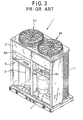
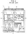
- Figs. 3 and 4 show an outdoor unit 1 with a back panel thereof being detached, where Fig. 3 is a perspective view of the outdoor unit 1 when an inner panel is further detached and Fig. 4 is a front view of the outdoor unit 1 which is viewed from the back side thereof.
- the outdoor unit 1 of the air conditioner includes a housing 2, a first compressor 3 for a constant speed driving operation, a second compressor 10 for an inverter driving operation, an accumulator 4 and a receiver tank (not shown), etc. which are accommodated in the housing 2.
- the outdoor unit 1 further includes an electrical-equipment box 8 which is accommodated at the upper space of the inside of the housing 2 so as to be filled in the space in the width direction of the housing.
- a heat exchanger is further disposed at the back side of the outdoor unit 1, and air is ventilated to the heat exchanger through an air suction port 11 at the side surface of the housing 2 by a pair of fans 5a and 5b.
- These equipments are disposed in the housing 2 while partitioned into a group of equipments having high heating value and a group of equipments having low heating value. Those equipments which have a relatively high heating value are disposed at a first space 6 at the left side of Fig. 4 (at a side portion beneath the electrical-equipment box 8) while those equipments which have a relatively low heating value are disposed at a second space 7 at the right side (at the other side portion beneath the electrical-equipment box 8).
- the first and second compressors 3 and 10 which have the relatively higher heating value in the equipments of a refrigeration circuit, and equipments appendant to the compressors.
- an inverter driving circuit for driving the compressors, the other equipments of the outdoor unit and control circuits.
- Fig. 5 is a block diagram showing an electrical circuit of the inverter driving circuit.
- alternating power is supplied from a three-phase power source 12 is supplied through a terminal board to the inverter driving circuit in the electrical-equipment box 8.
- the terminal board 13 is connected to a noise filter 14.
- the noise filter 14 serves to remove a noise N1 (impulse noise or the like) which invades from the three-phase power source 12 side to a converter portion of the circuit, and an LC integration type filter or the like may be used as the noise filter 14.
- the output of the noise filter 14 is supplied through a magnet switch 15 to a bridge diode 16.
- the bridge diode 16 is a bridge-connection type of full-wave rectifier, and serves to rectify the three-phase alternating power to DC power.
- the DC output of the bridge diode 16 is smoothed by a smoothing circuit comprising a noise filter 17, a reactor 18 and a capacitor 19, and then supplied to a transistor module 21.
- the noise filter 17 serves to prevent a high-frequency switching noise N2 produced in the transistor module 21 from invading into the converter portion 22.
- the transistor module 21 drives the second compressor 10 under control of a controller 20, for example, under the variable frequency control based on PWM (pulse width modulation) control.
- PWM pulse width modulation
- This document discloses a device for reducing the leakage noise of a power converter having a rectifier circuit connected to an alternating current power source and an inverter circuit connected to the rectifier circuit comprising a first and a second noise filter each with a plurality of inductors and capacitors.
- the inverter driving circuit comprises many circuit elements (parts). These circuit elements have been conventionally laid out in consideration of facility of fabrication, draw-out of wirings, management of heat, etc. However, the conventional circuit arrangement has been considered mainly in terms of productivity such as facility of fabrication, etc., so that attention is little paid to a countermeasure to electrical characteristics, particularly noises.
- the circuit arrangement is made such that the wirings of the three-phase power source 12 and the wirings in the converter portion 22 approach to each other or cross each other, or the wirings of the inverter portion 23 and the wirings of the converter portion 22 approach to each other or cross each other. Therefore, in some cases the noise filters 14 and 17 do not effectively work.
- a driving power-source frequency is varied in accordance with an air conditioning load, in a frequency range of 15 to 75Hz for example, to adjust a compression power (capacity) of the compressor.
- the variable control of the driving power-source frequency is performed by a controller (CPU) which is built in the electrical-equipment box 8 (Fig. 4) of the air conditioner.
- Fig. 6 shows the conventional inverter driving circuit and the controller.
- three-phase alternating power (R-phase, S-phase, T-phase) which is supplied from a three-phase four-wire type of alternating power source 31 having a neutral point N is input to a noise filter 32.
- the noise filter 32 comprises an LC integration type of noise filter containing a reactor and capacitor, and serves to remove noises (particularly high-frequency noises) contained in the power supplied from the three-phase alternating power source 31 to the noise-removed alternating power to a rectifier (rectifying circuit) 33.
- the rectifier 33 comprises a three-phase bridge rectifying circuit having diodes, and serves to convert the supplied alternating power to DC power.
- the DC power thus obtained is input to a smoothing circuit comprising a reactor 34 and a smoothing capacitor 35 to remove ripple components, and then supplied to a transistor module 36.
- the transistor module 36 On the basis of the supplied DC power, the transistor module 36 generates alternating power having a desired frequency using PWM control in accordance with a control signal which is supplied from the controller 38 through a control signal line 40, thereby driving a compressor motor of the compressor 7.
- the other equipments are represented by reference numeral 41.
- a power source for the controller is designed to commonly use the DC power produced in the inverter driving circuit, and thus the DC power is drawn in from the output stage of the smoothing circuit (reactor 34, smoothing capacitor 35) through a power source wiring 39.
- the conventional inverter driving circuit as described above has an advantage that the circuit construction can be simplified because of the common use of the power source.
- the DC power is directly supplied from the input stage of the transistor module (the output stage of the reactor 34, the smoothing capacitor 35) to the controller 38, so that a switching noise emitted from the transistor module 36, that is, a high-frequency noise of PWM wave is contaminated through the power source wiring 39 into the controller 38 to adversely affect the operation of the controller 38.
- the three-phase four-wiring type of alternating power source is actuated at a relatively high voltage (for example, AC380V), and the input voltage of the transistor module 36 is set to a high voltage (for example, DC537V). Therefore, a transformer which is designed to have high resistance to voltage must be used for a switching regulator of a power source portion built in the controller 38, and it must be designed in large size in consideration of insulation. That is, restriction is imposed on miniaturization of the device.
- an inverter driving circuit which comprises a rectifying circuit for converting the supplied alternating power to DC power, a transistor module for generating and outputting variable-frequency alternating power on the basis of the DC power and a controller for supplyinc said transistor module with a control signal.
- a power supply for the controller a separate DC voltage source is provided.
- An object of the present invention is to provide a circuit wiring arrangement for an inverter driving circuit noise contamination can be suppressed.
- Another object of the present invention is to provide an air conditioner in which noise contamination from a transistor module can be suppressed.
- a noise-existing portion at the front side of the noise filter and a noise-removed portion at the rear side of the noise filter are disposed so that they do not approach to each other or do not cross each other, and thus the noise filter can effectively work. Further, the circuit elements are disposed along the power supply path, so that noise contamination can be prevented with short wirings.
- the noise contamination can be also prevented between the inverter portion and the converter portion.
- the space in which the respective circuit elements are disposed away from each other i.e., the spatially-separating space for the circuit elements
- the spatially-separating space for the circuit elements can be effectively used, and assurance of the spatial separation arrangement can be improved.
- the power source of the controller is supplied with the alternating power from the neutral point of the noise filter and any one phase (R, S or T) of the noise filter, and the high-frequency noise occurring in the transistor module can be intercepted by a smoothing circuit and a rectifying circuit, so that the noise contamination into the controller can be prevented.
- the alternating power supplied to the controller is a voltage applied across the neutral point and any one phase of the noise filter, and thus it may be a low voltage unlike a voltage based on a high line voltage of the prior art, so that the voltage resistance of a transformer of a switching regulator can be more reduced and the transformer can be miniaturized.
- Fig. 1 shows a first embodiment of the inverter driving circuit of the invention.
- the electrical circuit of the inventer driving circuit is similar to that of Fig. 5, and the detailed description thereof is omitted.
- the circuit elements of the inverter driving circuit are arranged along a power supply path through which three-phase alternating power flows from the three-phase power source 12 to the output stage of the transistor module 21 so that the wirings between the respective circuit elements are disposed away from one another (spatially separately arranged) without approaching to each other or crossing each other.
- the terminal board 13 is disposed at one side portion of the electrical-equipment box 8, and the noise filter 14 is disposed to the other side portion of the electrical-equipment box 8, which is opposite to the one side portion at which the terminal board 13 is disposed.
- the magnet switch 15 is disposed at the same side portion as the terminal board 13, however, away from the terminal board 13 as shown in Fig. 1. That is, the circuit elements are arranged in a zigzag form as a whole.
- a noise-existing area containing those circuit elements which may potentially produce noises and a noise-removed area containing those circuit elements from which the noises are removed are arranged not to be contaminated with each other with the noise filters 14 and 17 at the boundary. Therefore, the noise filters 14 and 17 can be effectively used, and their original function can effectively work.
- the lay-out pattern of the circuit elements of the inverter driving circuit is not limited to the above embodiment, and the size or shape of the circuit elements are determined in accordance with the size or shape of the other electrical equipments 25, the centralized control board 24 and the controller 20. That is, various modifications may be suitably made to the above embodiment without departing from the subject matter of the present invention.
- the noise filters can be effectively used to prevent the operation of the device from being unstable due to noise contamination, and improve its reliability.
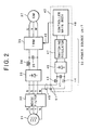
- Fig. 2 shows a second embodiment of the inverter driving circuit according to the present invention and a power source 50 for the controller.
- the same elements as shown in Fig. 6 are represented by the same reference numerals, and the description thereof is omitted.
- the wiring arrangement of this embodiment is made so that the power-source terminal 51 of a controller 42 is supplied with alternating power applied across the neutral point N and the R-phase of the output terminal of the noise filter 32 through a power-source wiring 49.
- the power source terminal 51 is connected to a reactor 43, 44 and a smoothing capacitor 45.
- the reactor 43, 44 and the smoothing capacitor 45 constitutes a noise filter. Therefore, the noise contamination into the controller 42 is prevented doubly.
- the rectifying circuit 46 comprises a bridge rectifying circuit of diodes.
- the DC power is supplied to a switching regulator 47 to improve regulation, that is, stabilize the power, and then supplied to a power source of a controller main body 48.
- a self-oscillation type using a high-frequency transformer may be used as the switching regulator 47.
- An LC smoothing circuit is preferably used at the output stage of the rectifying circuit to stabilize the power source.
- the power to be supplied to the power source of the controller is taken out from the neutral point and one phase between the output stage of the noise filter and the input stage of the rectifying circuit, so that noises from the transistor module can be intercepted and the power source portion can be miniaturized because of reduction of the power source voltage.
Landscapes
- Engineering & Computer Science (AREA)
- Power Engineering (AREA)
- Chemical & Material Sciences (AREA)
- Combustion & Propulsion (AREA)
- Mechanical Engineering (AREA)
- General Engineering & Computer Science (AREA)
- Inverter Devices (AREA)
- Air Conditioning Control Device (AREA)
Description
- This invention relates to a variable frequency control type of air conditioner using an inverter power source, and particularly to the improvement of a mount technique for parts of an inverter driving circuit which is mounted in an electrical-equipment box built in an air conditioner and the improvement of a power source for a controller for an inverter driving circuit.
- In general, an outdoor unit of an air conditioner contains therein equipments such as a heat exchanger, a compressor, an accumulator, etc. and an electrical-equipment box for electrical equipments for driving the above equipments.
- Figs. 3 and 4 show an
outdoor unit 1 with a back panel thereof being detached, where Fig. 3 is a perspective view of theoutdoor unit 1 when an inner panel is further detached and Fig. 4 is a front view of theoutdoor unit 1 which is viewed from the back side thereof. As shown in Figs. 3 and 4, theoutdoor unit 1 of the air conditioner includes ahousing 2, afirst compressor 3 for a constant speed driving operation, asecond compressor 10 for an inverter driving operation, anaccumulator 4 and a receiver tank (not shown), etc. which are accommodated in thehousing 2. Theoutdoor unit 1 further includes an electrical-equipment box 8 which is accommodated at the upper space of the inside of thehousing 2 so as to be filled in the space in the width direction of the housing. A heat exchanger is further disposed at the back side of theoutdoor unit 1, and air is ventilated to the heat exchanger through anair suction port 11 at the side surface of thehousing 2 by a pair offans 5a and 5b. - These equipments are disposed in the
housing 2 while partitioned into a group of equipments having high heating value and a group of equipments having low heating value. Those equipments which have a relatively high heating value are disposed at afirst space 6 at the left side of Fig. 4 (at a side portion beneath the electrical-equipment box 8) while those equipments which have a relatively low heating value are disposed at asecond space 7 at the right side (at the other side portion beneath the electrical-equipment box 8). - That is, in the
first space 6 are disposed the first andsecond compressors equipment box 8 are disposed an inverter driving circuit for driving the compressors, the other equipments of the outdoor unit and control circuits. - Fig. 5 is a block diagram showing an electrical circuit of the inverter driving circuit. In Fig. 5, alternating power is supplied from a three-
phase power source 12 is supplied through a terminal board to the inverter driving circuit in the electrical-equipment box 8. Theterminal board 13 is connected to anoise filter 14. Thenoise filter 14 serves to remove a noise N1 (impulse noise or the like) which invades from the three-phase power source 12 side to a converter portion of the circuit, and an LC integration type filter or the like may be used as thenoise filter 14. The output of thenoise filter 14 is supplied through amagnet switch 15 to abridge diode 16. - The
bridge diode 16 is a bridge-connection type of full-wave rectifier, and serves to rectify the three-phase alternating power to DC power. The DC output of thebridge diode 16 is smoothed by a smoothing circuit comprising anoise filter 17, areactor 18 and acapacitor 19, and then supplied to atransistor module 21. Thenoise filter 17 serves to prevent a high-frequency switching noise N2 produced in thetransistor module 21 from invading into theconverter portion 22. On the basis of the supplied DC power, thetransistor module 21 drives thesecond compressor 10 under control of acontroller 20, for example, under the variable frequency control based on PWM (pulse width modulation) control. An inverter like the one illustrated in Fig. 5 less the magnet switch is disclosed in US-A-4849950. - This document discloses a device for reducing the leakage noise of a power converter having a rectifier circuit connected to an alternating current power source and an inverter circuit connected to the rectifier circuit comprising a first and a second noise filter each with a plurality of inductors and capacitors.
- As described above, the inverter driving circuit comprises many circuit elements (parts). These circuit elements have been conventionally laid out in consideration of facility of fabrication, draw-out of wirings, management of heat, etc. However, the conventional circuit arrangement has been considered mainly in terms of productivity such as facility of fabrication, etc., so that attention is little paid to a countermeasure to electrical characteristics, particularly noises.
- Specifically, irrespective of insertion of the
noise filter 14 and thenoise filter 17 in the circuit to remove the noises, in some cases the circuit arrangement is made such that the wirings of the three-phase power source 12 and the wirings in theconverter portion 22 approach to each other or cross each other, or the wirings of theinverter portion 23 and the wirings of theconverter portion 22 approach to each other or cross each other. Therefore, in some cases thenoise filters - On the other hand, in a variable frequency control type of air conditioner using an inverter driving circuit, a driving power-source frequency is varied in accordance with an air conditioning load, in a frequency range of 15 to 75Hz for example, to adjust a compression power (capacity) of the compressor. The variable control of the driving power-source frequency is performed by a controller (CPU) which is built in the electrical-equipment box 8 (Fig. 4) of the air conditioner.
- Fig. 6 shows the conventional inverter driving circuit and the controller. In Fig. 6, three-phase alternating power (R-phase, S-phase, T-phase) which is supplied from a three-phase four-wire type of
alternating power source 31 having a neutral point N is input to anoise filter 32. Thenoise filter 32 comprises an LC integration type of noise filter containing a reactor and capacitor, and serves to remove noises (particularly high-frequency noises) contained in the power supplied from the three-phasealternating power source 31 to the noise-removed alternating power to a rectifier (rectifying circuit) 33. Therectifier 33 comprises a three-phase bridge rectifying circuit having diodes, and serves to convert the supplied alternating power to DC power. The DC power thus obtained is input to a smoothing circuit comprising areactor 34 and asmoothing capacitor 35 to remove ripple components, and then supplied to atransistor module 36. On the basis of the supplied DC power, thetransistor module 36 generates alternating power having a desired frequency using PWM control in accordance with a control signal which is supplied from thecontroller 38 through acontrol signal line 40, thereby driving a compressor motor of thecompressor 7. The other equipments are represented by reference numeral 41. - In order to simplify the construction of the inverter driving circuit as described above, a power source for the controller is designed to commonly use the DC power produced in the inverter driving circuit, and thus the DC power is drawn in from the output stage of the smoothing circuit (
reactor 34, smoothing capacitor 35) through apower source wiring 39. - The conventional inverter driving circuit as described above has an advantage that the circuit construction can be simplified because of the common use of the power source.
- However, in this circuit, the DC power is directly supplied from the input stage of the transistor module (the output stage of the
reactor 34, the smoothing capacitor 35) to thecontroller 38, so that a switching noise emitted from thetransistor module 36, that is, a high-frequency noise of PWM wave is contaminated through thepower source wiring 39 into thecontroller 38 to adversely affect the operation of thecontroller 38. - Further, the three-phase four-wiring type of alternating power source is actuated at a relatively high voltage (for example, AC380V), and the input voltage of the
transistor module 36 is set to a high voltage (for example, DC537V). Therefore, a transformer which is designed to have high resistance to voltage must be used for a switching regulator of a power source portion built in thecontroller 38, and it must be designed in large size in consideration of insulation. That is, restriction is imposed on miniaturization of the device. In EP-A-0 521 467 an inverter driving circuit is disclosed which comprises a rectifying circuit for converting the supplied alternating power to DC power, a transistor module for generating and outputting variable-frequency alternating power on the basis of the DC power and a controller for supplyinc said transistor module with a control signal. As a power supply for the controller a separate DC voltage source is provided. - An object of the present invention is to provide a circuit wiring arrangement for an inverter driving circuit noise contamination can be suppressed.
- Another object of the present invention is to provide an air conditioner in which noise contamination from a transistor module can be suppressed.
- These objects are solved by the features of the
claims - Advantageous embodiments of the invention are mentioned in the subclaims.
- According to the first aspect of the present invention, a noise-existing portion at the front side of the noise filter and a noise-removed portion at the rear side of the noise filter are disposed so that they do not approach to each other or do not cross each other, and thus the noise filter can effectively work. Further, the circuit elements are disposed along the power supply path, so that noise contamination can be prevented with short wirings.
- According to the second aspect of the present invention, the noise contamination can be also prevented between the inverter portion and the converter portion.
- According to the third aspect of the present invention, the space in which the respective circuit elements are disposed away from each other (i.e., the spatially-separating space for the circuit elements) can be effectively used, and assurance of the spatial separation arrangement can be improved.
- According to the fourth aspect of the present invention, the power source of the controller is supplied with the alternating power from the neutral point of the noise filter and any one phase (R, S or T) of the noise filter, and the high-frequency noise occurring in the transistor module can be intercepted by a smoothing circuit and a rectifying circuit, so that the noise contamination into the controller can be prevented.
- Further, the alternating power supplied to the controller is a voltage applied across the neutral point and any one phase of the noise filter, and thus it may be a low voltage unlike a voltage based on a high line voltage of the prior art, so that the voltage resistance of a transformer of a switching regulator can be more reduced and the transformer can be miniaturized.
-
- Fig. 1 is a block diagram showing a first embodiment of an inverter driving circuit according to the present invention;
- Fig. 2 is a block diagram showing a second embodiment of the inverter driving circuit and a power source for a controller according to the present invention;
- Fig. 3 is a perspective view showing the inside a conventional outdoor unit of an air conditioner;
- Fig. 4 is a plan view showing the inside of the conventional outdoor unit;
- Fig. 5 is a block circuit diagram showing an electrical circuit of a conventional inverter driving circuit; and
- Fig. 6 is a block diagram showing the conventional inverter driving circuit and a power source for a controller.
-
- Preferred embodiments according to the present invention will be described hereunder with reference to the accompanying drawings.
- Fig. 1 shows a first embodiment of the inverter driving circuit of the invention. The electrical circuit of the inventer driving circuit is similar to that of Fig. 5, and the detailed description thereof is omitted.
- As shown in Fig. 1, the circuit elements of the inverter driving circuit are arranged along a power supply path through which three-phase alternating power flows from the three-
phase power source 12 to the output stage of thetransistor module 21 so that the wirings between the respective circuit elements are disposed away from one another (spatially separately arranged) without approaching to each other or crossing each other. - Specifically, the
terminal board 13 is disposed at one side portion of the electrical-equipment box 8, and thenoise filter 14 is disposed to the other side portion of the electrical-equipment box 8, which is opposite to the one side portion at which theterminal board 13 is disposed. Further, themagnet switch 15 is disposed at the same side portion as theterminal board 13, however, away from theterminal board 13 as shown in Fig. 1. That is, the circuit elements are arranged in a zigzag form as a whole. - According to this spatially-separated arrangement, a noise-existing area containing those circuit elements which may potentially produce noises and a noise-removed area containing those circuit elements from which the noises are removed are arranged not to be contaminated with each other with the noise filters 14 and 17 at the boundary. Therefore, the noise filters 14 and 17 can be effectively used, and their original function can effectively work.
- On the other hand, other electrical parts which are not directly associated with the inverter driving circuit, such as a
centralized control board 24, otherelectrical equipments 25, thecontroller 20, etc. are arranged to be interposed between the respective circuit elements constituting the inverter driving circuit. - The lay-out pattern of the circuit elements of the inverter driving circuit is not limited to the above embodiment, and the size or shape of the circuit elements are determined in accordance with the size or shape of the other
electrical equipments 25, thecentralized control board 24 and thecontroller 20. That is, various modifications may be suitably made to the above embodiment without departing from the subject matter of the present invention. - According to the above embodiment, the noise filters can be effectively used to prevent the operation of the device from being unstable due to noise contamination, and improve its reliability.
- Fig. 2 shows a second embodiment of the inverter driving circuit according to the present invention and a
power source 50 for the controller. In Fig. 2, the same elements as shown in Fig. 6 are represented by the same reference numerals, and the description thereof is omitted. - In Fig. 2, the wiring arrangement of this embodiment is made so that the power-
source terminal 51 of acontroller 42 is supplied with alternating power applied across the neutral point N and the R-phase of the output terminal of thenoise filter 32 through a power-source wiring 49. - In the
controller 42, thepower source terminal 51 is connected to areactor capacitor 45. Thereactor capacitor 45 constitutes a noise filter. Therefore, the noise contamination into thecontroller 42 is prevented doubly. Through the noise filter, the alternating power is converted to DC power by a rectifying circuit. The rectifyingcircuit 46 comprises a bridge rectifying circuit of diodes. The DC power is supplied to aswitching regulator 47 to improve regulation, that is, stabilize the power, and then supplied to a power source of a controllermain body 48. A self-oscillation type using a high-frequency transformer may be used as the switchingregulator 47. - An LC smoothing circuit is preferably used at the output stage of the rectifying circuit to stabilize the power source.
- According to the second embodiment as described above, the power to be supplied to the power source of the controller is taken out from the neutral point and one phase between the output stage of the noise filter and the input stage of the rectifying circuit, so that noises from the transistor module can be intercepted and the power source portion can be miniaturized because of reduction of the power source voltage.
Claims (8)
- An inverter driving circuit having various circuit elements for an air conditioner which comprises circuit elements and is installed in an electrical-equipment box (8), comprising:a first circuit element group (13, 25) including an alternating power source (13) and wire for connecting circuit elements thereof to one another;a second circuit element group (21) including a converter portion and wires for connecting circuit elements thereof to one another;a third circuit element group (18, 19) including an inverter portion and wires for connecting circuit elements thereof to one another;a controller (20) for connecting said inverter portion;a first noise filter (14) between said first circuit element group and said second circuit element group, said first noise filter positioned to remove noise from said first circuit element group from invading said second circuit element group; anda second noise filter (17) between said second circuit element group and said third circuit element group, said second noise filter positioned to remove noise from said third circuit element group from invading said second circuit element group, wherein said first circuit element group, wherein said second circuit element group and said third element group are arranged in a zigzag form such that electromagnetic noise of each circuit element group has minimal effect on another circuit element group.
- The inverter driving circuit as claimed in claim 1, wherein said controller (20) is interposed between at least two of said first circuit element groups, said first noise filter, said second circuit element group, said second noise filter and said third circuit element group.
- The inverter driving circuit as claimed in claim 1, wherein electrical parts other than said circuit elements constituting said inverter driving circuit are interposed between said circuit elements so that said circuit elements are arranged spatially separately from one another.
- The inverter driving circuit as claimed in claim 1, wherein said circuit elements are arranged alternately at one of both side portions of said electrical-equipment box (8) in a zigzag form along the power supply path so as to be away from one another.
- An air conditioner, comprising:wherein said controller (20) has a power source unit which is supplied power through a power-source wiring connected across a neutral point and one of three phases of said three-phase four-wire type of alternating power source at the output terminal of said noise filter, anda first circuit element group including an alternating power source (13) and wires for connecting circuit elements thereof to one another;a first noise filter (14) for removing noise components contained in power supplied from a three-phase four-wire type of alternating power source;a second circuit element group (21) including a rectifying circuit for inverting the supplied alternating power from said first noise filter to DC power, said first noise filter (14) positioned to remove noise from said first circuit element group from invading said second circuit element group;a third circuit element group including a transistor module for generating variable-frequency alternating power for a compressor driving operation on the DC power from said rectifying circuit; anda controller (20) for supplying said transistor module with a control signal for a variable frequency driving operation,
wherein said first circuit element group, said second circuit element group and said third circuit element group are arranged in a zigzag form such that electromagnetic noise of each circuit element group has minimal effect on another circuit element group. - The air conditioner as claimed in claim 5, further comprising a switching regulator for stabilizing the output of said rectifying circuit.
- An inverter driving circuit arrangement for driving a motor under variable frequency control of the type which includes:a three-phase alternating power source (12) having noise producing components within a first noise-containing area, an inverter (18, 19, 21:23) having noise producing components within a second noise-containing area,a converter circuit (13, 15, BD:22) comprising a terminal board (13) electrically connected to said three-phase alternating power source (12), a first noise filter (14) electrically connected to said terminal board (13) to remove noise components from alternating power provided by said three-phase alternating power source (12), a magnet switch (15) electrically connected to said first noise filter (14), a rectifier (BD, 16) electrically connected to said magnet switch (15) to convert the alternating power having the noise components removed therefrom to DC power, and a second noise filter (17) electrically connected between said rectifier (BD, 16) and said inverter (23) to remove noise components from said inverter (23),said inverter (23) including at least a transistor module (21) for converting said DC power to AC power for driving the motor under variable frequency control, andan electrical equipment box (8) for housing said inverter (23) and said converter circuit (22), said electrical equipment box (8) having parallel first and second sides (A, B) extending in a predetermined direction and being spaced from one another,the inverter driving circuit arrangement comprising:each of said terminal board (13), said magnet switch (15), said rectifier (16), and said inverter (23: 18, 14, 21) being positioned adjacent said first side of said electrical equipment box,said first noise filter and said second noise filter being positioned adjacent said second side (A) of said electrical equipment box clear of said first and second noise-containing areas.
- An inverter driving circuit arrangement, comprising:a first noise filter (32) having an input terminal electrically connected to a three-phase alternating power source (31) having noise producing components within a first noise-containing area and an output terminal having a neutral connection and three-phase output connections, said first noise filter (32) removing noise components from the alternating power provided by said three-phase alternating power source (12);a first rectifier (33) electrically connected to said first noise filter (32) to convert said three-phase alternating power having said noise components removed therefrom to DC power;an inverter (34, 35, 36) having noise producing components within a second noise containing area, said inverter being electrically connected to said first rectifier (33) to convert said DC power to alternating power for driving a motor under variable frequency control; anda controller (50) for controlling said inverter, said controller comprising power source terminals electrically connected across said neutral connection and one of said three-phase output connections of said first noise filter,a second noise filter (43, 44, 45) electrically connected to said power source terminals for removing noise components of said inverter, a second rectifier (46) electrically connected to said second noise filter to convert said alternating power having said noise components removed therefrom to DC power, a switching regulator (47) electrically connected to said second rectifier (46) to stabilize said DC power, and an inverter control unit (48) electrically connected to said switching regulator (47) and said inverter to control said inverter on the basis of said DC power having said noise components removed therefrom,said first and second noise filters being positioned clear of said first and second noise-containing areas.
Applications Claiming Priority (6)
| Application Number | Priority Date | Filing Date | Title |
|---|---|---|---|
| JP5336627A JPH07190417A (en) | 1993-12-28 | 1993-12-28 | Inverter drive circuit |
| JP33662793 | 1993-12-28 | ||
| JP336627/93 | 1993-12-28 | ||
| JP00168894A JP3579075B2 (en) | 1994-01-12 | 1994-01-12 | Air conditioner |
| JP1688/94 | 1994-01-12 | ||
| JP168894 | 1994-01-12 |
Publications (3)
| Publication Number | Publication Date |
|---|---|
| EP0661453A2 EP0661453A2 (en) | 1995-07-05 |
| EP0661453A3 EP0661453A3 (en) | 1997-10-29 |
| EP0661453B1 true EP0661453B1 (en) | 2003-04-23 |
Family
ID=26334961
Family Applications (1)
| Application Number | Title | Priority Date | Filing Date |
|---|---|---|---|
| EP94120432A Expired - Lifetime EP0661453B1 (en) | 1993-12-28 | 1994-12-22 | Air conditioner and inverter driving circuit therefor |
Country Status (5)
| Country | Link |
|---|---|
| US (1) | US5764022A (en) |
| EP (1) | EP0661453B1 (en) |
| KR (1) | KR950019512A (en) |
| DE (1) | DE69432554T2 (en) |
| ES (1) | ES2197155T3 (en) |
Families Citing this family (13)
| Publication number | Priority date | Publication date | Assignee | Title |
|---|---|---|---|---|
| US6064173A (en) * | 1997-06-26 | 2000-05-16 | Allen-Bradley Company, Llc | Application-specific electronic motor starter |
| JPH1113635A (en) * | 1997-06-30 | 1999-01-19 | Matsushita Electric Ind Co Ltd | Compressor drive |
| TW407394B (en) * | 1997-10-16 | 2000-10-01 | Toshiba Corp | Frequency converter to output electric driving power to motor and filter installed on it |
| TW366403B (en) * | 1998-02-03 | 1999-08-11 | Sanyo Electric Co | Apparatus for controlling an air conditioner |
| DE19962728A1 (en) | 1999-12-23 | 2001-06-28 | Grundfos As | Cooler |
| JP4107789B2 (en) * | 2000-08-10 | 2008-06-25 | 三洋電機株式会社 | Power supply reverse phase detection circuit |
| USD456353S1 (en) | 2000-11-09 | 2002-04-30 | Acumentrics Corporation | Power supply enclosure |
| US6531842B2 (en) | 2001-06-25 | 2003-03-11 | Schlumberger Technology Corp. | Sine wave variable speed drive |
| KR100858537B1 (en) * | 2002-09-03 | 2008-09-16 | 엘지전자 주식회사 | Leakage Current Attenuation Circuit of Inverter Air Conditioner |
| KR20090053491A (en) * | 2007-11-23 | 2009-05-27 | 엘지전자 주식회사 | Outdoor unit of air conditioner |
| JP5062347B1 (en) * | 2011-05-02 | 2012-10-31 | ダイキン工業株式会社 | Power conversion circuit and air conditioner |
| KR101575253B1 (en) * | 2014-08-27 | 2015-12-07 | 현대자동차 주식회사 | Main semiconductor device for air conditioner and vehicle air conditioner system having the same |
| JP6393287B2 (en) * | 2016-01-27 | 2018-09-19 | 日立ジョンソンコントロールズ空調株式会社 | Air conditioner outdoor unit |
Family Cites Families (10)
| Publication number | Priority date | Publication date | Assignee | Title |
|---|---|---|---|---|
| JPS6059978A (en) * | 1983-09-12 | 1985-04-06 | Toshiba Corp | Air conditioner |
| JPH0612954B2 (en) * | 1984-11-27 | 1994-02-16 | 株式会社東芝 | Synchronous motor control method |
| US4879639A (en) * | 1987-05-11 | 1989-11-07 | Fuji Electric Co., Ltd. | Power converter for driving an AC motor at a variable speed |
| JPS6485574A (en) * | 1987-09-28 | 1989-03-30 | Toshiba Corp | Power converting device |
| DE58905173D1 (en) * | 1988-11-04 | 1993-09-09 | Europ Patent Ag | METHOD AND DEVICE FOR CHANGING THE ACTUAL SPEED OF A MULTI-PHASE ASYNCHRONOUS MOTOR, AND MOTOR SYSTEM SUITABLE FOR IMPLEMENTING THE METHOD. |
| US4894763A (en) * | 1988-12-05 | 1990-01-16 | General Electric Company | AC-AC converter using switches in a DC link |
| JPH03155392A (en) * | 1989-11-10 | 1991-07-03 | Toshiba Corp | Current detecting unit |
| JPH0479773A (en) * | 1990-07-20 | 1992-03-13 | Fujitsu General Ltd | air conditioner |
| JPH0513562A (en) * | 1991-07-05 | 1993-01-22 | Hitachi Ltd | Drive controller |
| JPH05300757A (en) * | 1992-04-23 | 1993-11-12 | Daikin Ind Ltd | Motor controller |
-
1994
- 1994-12-22 DE DE69432554T patent/DE69432554T2/en not_active Expired - Lifetime
- 1994-12-22 EP EP94120432A patent/EP0661453B1/en not_active Expired - Lifetime
- 1994-12-22 ES ES94120432T patent/ES2197155T3/en not_active Expired - Lifetime
- 1994-12-27 KR KR1019940037229A patent/KR950019512A/en not_active Withdrawn
-
1996
- 1996-11-21 US US08/754,514 patent/US5764022A/en not_active Expired - Lifetime
Also Published As
| Publication number | Publication date |
|---|---|
| US5764022A (en) | 1998-06-09 |
| KR950019512A (en) | 1995-07-24 |
| ES2197155T3 (en) | 2004-01-01 |
| EP0661453A3 (en) | 1997-10-29 |
| DE69432554D1 (en) | 2003-05-28 |
| DE69432554T2 (en) | 2004-03-25 |
| EP0661453A2 (en) | 1995-07-05 |
Similar Documents
| Publication | Publication Date | Title |
|---|---|---|
| US5530635A (en) | Power supply | |
| JP6738456B2 (en) | Electromagnetic compatibility filter | |
| US5764022A (en) | Air conditioner and inverter driving circuit therefor | |
| CA2764994C (en) | Enclosure housing electronic components having hybrid hvac/r system with power back-up | |
| US6836416B2 (en) | Multi-output power conversion circuit | |
| HK1005353B (en) | Power supply | |
| JP4065008B2 (en) | Distributed DC power network | |
| EP2063527A2 (en) | Motor controller of air conditioner | |
| US5598328A (en) | Filter module for a frequency converter | |
| CN108692439A (en) | Transducer air conditioning circuit board, transducer air conditioning | |
| CN111181413B (en) | Power conversion system and filter for the power conversion system | |
| JPWO2020208825A1 (en) | Power converter and air conditioner | |
| JPH11341775A (en) | Power tool with brushless drive motor | |
| US5124567A (en) | Power supply device and electronic apparatus using the same | |
| EP1198058B1 (en) | Single-phase ac-dc converter | |
| AU2009247443A1 (en) | Filter circuit mounting unit and power supply unit | |
| JP2021118476A (en) | Noise filter, noise filter device, and power converter | |
| JP3579075B2 (en) | Air conditioner | |
| EP3591829A1 (en) | Power conversion device | |
| CN1169212A (en) | Circuit | |
| JPH08317638A (en) | Power converter | |
| US20240244790A1 (en) | Power control unit for electric vehicle | |
| JPH0817571B2 (en) | Compression cooling device | |
| JP7696863B2 (en) | Heat source unit | |
| JPH08163876A (en) | Air conditioner inverter device |
Legal Events
| Date | Code | Title | Description |
|---|---|---|---|
| PUAI | Public reference made under article 153(3) epc to a published international application that has entered the european phase |
Free format text: ORIGINAL CODE: 0009012 |
|
| AK | Designated contracting states |
Kind code of ref document: A2 Designated state(s): DE ES FR GB IT |
|
| 17P | Request for examination filed |
Effective date: 19950814 |
|
| PUAL | Search report despatched |
Free format text: ORIGINAL CODE: 0009013 |
|
| AK | Designated contracting states |
Kind code of ref document: A3 Designated state(s): DE ES FR GB IT |
|
| 17Q | First examination report despatched |
Effective date: 19990625 |
|
| GRAH | Despatch of communication of intention to grant a patent |
Free format text: ORIGINAL CODE: EPIDOS IGRA |
|
| GRAH | Despatch of communication of intention to grant a patent |
Free format text: ORIGINAL CODE: EPIDOS IGRA |
|
| GRAA | (expected) grant |
Free format text: ORIGINAL CODE: 0009210 |
|
| AK | Designated contracting states |
Designated state(s): DE ES FR GB IT |
|
| REG | Reference to a national code |
Ref country code: GB Ref legal event code: FG4D |
|
| REF | Corresponds to: |
Ref document number: 69432554 Country of ref document: DE Date of ref document: 20030528 Kind code of ref document: P |
|
| ET | Fr: translation filed | ||
| REG | Reference to a national code |
Ref country code: ES Ref legal event code: FG2A Ref document number: 2197155 Country of ref document: ES Kind code of ref document: T3 |
|
| PLBE | No opposition filed within time limit |
Free format text: ORIGINAL CODE: 0009261 |
|
| STAA | Information on the status of an ep patent application or granted ep patent |
Free format text: STATUS: NO OPPOSITION FILED WITHIN TIME LIMIT |
|
| 26N | No opposition filed |
Effective date: 20040126 |
|
| PGFP | Annual fee paid to national office [announced via postgrant information from national office to epo] |
Ref country code: IT Payment date: 20081229 Year of fee payment: 15 |
|
| PGFP | Annual fee paid to national office [announced via postgrant information from national office to epo] |
Ref country code: ES Payment date: 20091229 Year of fee payment: 16 |
|
| PGFP | Annual fee paid to national office [announced via postgrant information from national office to epo] |
Ref country code: GB Payment date: 20091216 Year of fee payment: 16 Ref country code: FR Payment date: 20091221 Year of fee payment: 16 |
|
| PGFP | Annual fee paid to national office [announced via postgrant information from national office to epo] |
Ref country code: DE Payment date: 20091217 Year of fee payment: 16 |
|
| PG25 | Lapsed in a contracting state [announced via postgrant information from national office to epo] |
Ref country code: IT Free format text: LAPSE BECAUSE OF NON-PAYMENT OF DUE FEES Effective date: 20091222 |
|
| GBPC | Gb: european patent ceased through non-payment of renewal fee |
Effective date: 20101222 |
|
| REG | Reference to a national code |
Ref country code: FR Ref legal event code: ST Effective date: 20110831 |
|
| PG25 | Lapsed in a contracting state [announced via postgrant information from national office to epo] |
Ref country code: FR Free format text: LAPSE BECAUSE OF NON-PAYMENT OF DUE FEES Effective date: 20110103 |
|
| REG | Reference to a national code |
Ref country code: DE Ref legal event code: R119 Ref document number: 69432554 Country of ref document: DE Effective date: 20110701 |
|
| PG25 | Lapsed in a contracting state [announced via postgrant information from national office to epo] |
Ref country code: DE Free format text: LAPSE BECAUSE OF NON-PAYMENT OF DUE FEES Effective date: 20110701 Ref country code: GB Free format text: LAPSE BECAUSE OF NON-PAYMENT OF DUE FEES Effective date: 20101222 |
|
| REG | Reference to a national code |
Ref country code: ES Ref legal event code: FD2A Effective date: 20120206 |
|
| PG25 | Lapsed in a contracting state [announced via postgrant information from national office to epo] |
Ref country code: ES Free format text: LAPSE BECAUSE OF NON-PAYMENT OF DUE FEES Effective date: 20101223 |