EP0661069A2 - Spray container for spraying medicinal liquid to mucous membrane of throat - Google Patents
Spray container for spraying medicinal liquid to mucous membrane of throat Download PDFInfo
- Publication number
- EP0661069A2 EP0661069A2 EP94309812A EP94309812A EP0661069A2 EP 0661069 A2 EP0661069 A2 EP 0661069A2 EP 94309812 A EP94309812 A EP 94309812A EP 94309812 A EP94309812 A EP 94309812A EP 0661069 A2 EP0661069 A2 EP 0661069A2
- Authority
- EP
- European Patent Office
- Prior art keywords
- medicinal liquid
- nozzle tip
- spray
- throat
- spray container
- Prior art date
- Legal status (The legal status is an assumption and is not a legal conclusion. Google has not performed a legal analysis and makes no representation as to the accuracy of the status listed.)
- Granted
Links
- 239000007921 spray Substances 0.000 title claims abstract description 38
- 239000007788 liquid Substances 0.000 title claims abstract description 33
- 210000004400 mucous membrane Anatomy 0.000 title claims abstract description 18
- 238000005507 spraying Methods 0.000 title claims abstract description 18
- 238000002347 injection Methods 0.000 claims abstract description 25
- 239000007924 injection Substances 0.000 claims abstract description 25
- 238000005086 pumping Methods 0.000 claims abstract description 5
- 230000002093 peripheral effect Effects 0.000 claims description 3
- 229920003023 plastic Polymers 0.000 claims 1
- 239000004033 plastic Substances 0.000 claims 1
- 239000011347 resin Substances 0.000 claims 1
- 229920005989 resin Polymers 0.000 claims 1
- 210000004379 membrane Anatomy 0.000 description 3
- 239000012528 membrane Substances 0.000 description 3
- 210000000621 bronchi Anatomy 0.000 description 1
- 230000000994 depressogenic effect Effects 0.000 description 1
- 210000002249 digestive system Anatomy 0.000 description 1
- 210000004072 lung Anatomy 0.000 description 1
- 229920003002 synthetic resin Polymers 0.000 description 1
- 239000000057 synthetic resin Substances 0.000 description 1
Images


Classifications
-
- B—PERFORMING OPERATIONS; TRANSPORTING
- B05—SPRAYING OR ATOMISING IN GENERAL; APPLYING FLUENT MATERIALS TO SURFACES, IN GENERAL
- B05B—SPRAYING APPARATUS; ATOMISING APPARATUS; NOZZLES
- B05B1/00—Nozzles, spray heads or other outlets, with or without auxiliary devices such as valves, heating means
- B05B1/14—Nozzles, spray heads or other outlets, with or without auxiliary devices such as valves, heating means with multiple outlet openings; with strainers in or outside the outlet opening
-
- A—HUMAN NECESSITIES
- A61—MEDICAL OR VETERINARY SCIENCE; HYGIENE
- A61M—DEVICES FOR INTRODUCING MEDIA INTO, OR ONTO, THE BODY; DEVICES FOR TRANSDUCING BODY MEDIA OR FOR TAKING MEDIA FROM THE BODY; DEVICES FOR PRODUCING OR ENDING SLEEP OR STUPOR
- A61M11/00—Sprayers or atomisers specially adapted for therapeutic purposes
-
- B—PERFORMING OPERATIONS; TRANSPORTING
- B05—SPRAYING OR ATOMISING IN GENERAL; APPLYING FLUENT MATERIALS TO SURFACES, IN GENERAL
- B05B—SPRAYING APPARATUS; ATOMISING APPARATUS; NOZZLES
- B05B1/00—Nozzles, spray heads or other outlets, with or without auxiliary devices such as valves, heating means
- B05B1/34—Nozzles, spray heads or other outlets, with or without auxiliary devices such as valves, heating means designed to influence the nature of flow of the liquid or other fluent material, e.g. to produce swirl
- B05B1/3405—Nozzles, spray heads or other outlets, with or without auxiliary devices such as valves, heating means designed to influence the nature of flow of the liquid or other fluent material, e.g. to produce swirl to produce swirl
- B05B1/341—Nozzles, spray heads or other outlets, with or without auxiliary devices such as valves, heating means designed to influence the nature of flow of the liquid or other fluent material, e.g. to produce swirl to produce swirl before discharging the liquid or other fluent material, e.g. in a swirl chamber upstream the spray outlet
- B05B1/3421—Nozzles, spray heads or other outlets, with or without auxiliary devices such as valves, heating means designed to influence the nature of flow of the liquid or other fluent material, e.g. to produce swirl to produce swirl before discharging the liquid or other fluent material, e.g. in a swirl chamber upstream the spray outlet with channels emerging substantially tangentially in the swirl chamber
- B05B1/3431—Nozzles, spray heads or other outlets, with or without auxiliary devices such as valves, heating means designed to influence the nature of flow of the liquid or other fluent material, e.g. to produce swirl to produce swirl before discharging the liquid or other fluent material, e.g. in a swirl chamber upstream the spray outlet with channels emerging substantially tangentially in the swirl chamber the channels being formed at the interface of cooperating elements, e.g. by means of grooves
- B05B1/3436—Nozzles, spray heads or other outlets, with or without auxiliary devices such as valves, heating means designed to influence the nature of flow of the liquid or other fluent material, e.g. to produce swirl to produce swirl before discharging the liquid or other fluent material, e.g. in a swirl chamber upstream the spray outlet with channels emerging substantially tangentially in the swirl chamber the channels being formed at the interface of cooperating elements, e.g. by means of grooves the interface being a plane perpendicular to the outlet axis
Definitions
- This invention relates to an improvement to a spray container for spraying medicinal liquid to inflamed or otherwise troubled mucous membrane of the throat for treatment.
- Spray containers are popularly used in recent years for spraying medicinal liquid to inflamed or otherwise troubled mucous membrane of the throat as well as for other purposes. Since conventional spray containers of the form under consideration comprises a nozzle tip provided with a single injection port through which medicinal liquid is injected in the form of a single cylindrical stream, they can cover only a small area of the membrane with a single injecting action.
- liquid is injected toward the mucous membrane of the throat from a spray container having an injection port with a diameter of 0.4mm and separated from the membrane by 10cm, only a surface area of 1.5cm2 of the membrane is covered by liquid with a single injecting action so that liquid has to be injected for a number of times with varied angles of injection in order to fully cover the entire mucous membrane of the throat.
- Medicinal liquid needs to be injected in the form of a cylindrical stream in order to prevent it from being inadvertently inhaled into the bronchi and then into the lungs.
- this arrangement is accompanied by the problem that the applied medicinal liquid is, at least partly, swallowed down into the digestive system as the amount of liquid increases with repeated injecting actions.
- a spray container comprising a spray head and a container main body wherein said spray head has a nozzle tip and said nozzle tip is provided with a pair of injection ports. Said injection ports are horizontally juxtaposed.
- a remarkably large area of the mucous membrane of the throat can be covered by medicinal liquid with a single spraying action so that the entire surface of the mucous membrane of the throat can be covered by liquid with a significantly reduced number of spraying actions as compared with the case using a conventional spray container and consequently the amount of medicinal liquid that is swallowed down by the subject can be significantly reduced.
- a desired profile of injected medicinal liquid and a desired coverage of medicinal liquid on the mucous membrane of the throat can be obtained by appropriately selecting the diameter of the injection ports and the distance separating the spray container from the mucous membrane.
- Figs. 1 through 5 illustrate an embodiment of spray container for spraying a medicinal liquid to a mucous membrane of a throat in accordance with the present invention.
- the spray container is generally denoted by reference numeral 1 and comprises a spray head 3 provided with a nozzle tip 2 and a container main body 4 for storing a medicinal liquid.
- the spray container includes a pumping mechanism.
- the spray head 3 provided with the nozzle tip 2 is depressed by a finger along the direction indicated by arrow X
- the medicinal liquid in the container main body 4 is pumped up from the container main body 4 and injected through a pair of injection ports 5 and 8 of the nozzle tip 2 toward the mucous membrane of the throat. Since the hydrodynamics or the pumping mechanism of this spray container is same as that of any known conventional spray containers, it will not be specifically described any further nor illustrated in the accompanying drawings.
- the spray head 3 of of the spray container 1 for spraying the medicinal liquid comprises a nozzle main body 6 and a nozzle tip 2.
- the nozzle tip comprises an elliptical front panel 7 and a peripheral wall 12.
- the elliptical front panel 7 is provided with the injection ports 5, 8.
- a pair of injection ports 5, 8 are horizontally juxtaposed on the elliptical front panel 7 and separated from each other by distance L as shown in Figs. 3, 4 and 5.
- the front panel 7 is provided at a rear side thereof with a pair of nozzle sacks 11, 11 coaxially aligned with the respective injection ports 5, 8.
- a pair of spin grooves 9, 10 are formed at an outer periphery of the nozzle sack 11, so that the medicinal liquid is injected from each of the injection ports 5, 8 as spiral vortex.
- the peripheral wall 12 of the nozzle tip 2 is used for rigidly and engagedly fitting the nozzle tip 2 into a front end of a medicinal liquid flow path 13 of the spray head 3.
- the spray container 1 may be made of synthetic resin.
- the nozzle tip provided with a pair of injection ports 5 and 8 having a diameter of 0.25mm and being separated from each other by distance L of 7mm was used with the above described conventional pumping mechanism and the container main body.
- a conventional nozzle tip having a single injection port with a diameter of 0.4mm was used.
- an area covered by a single spraying action of the nozzle tip located 10cm away from a target was 2.2cm2.
- the area covered by a single spraying action of the nozzle tip located 10cm away from a target was 1.5cm2. This means that the present invention shows an increase of approximately 46% in the area covered by a single spraying action and located 10cm away from the target.
- the diameter of the injection port and the distance L are not limited to the above described experimental example.
- a nozzle tip according to the invention can remarkably increase the coverage of sprayed medicinal liquid by single spraying action, the amount of medicinal liquid consumed in the spraying action is substantially same as the amount consumed by a comparable conventional nozzle tip, because the diameter of the injection ports can be reduced to about 60% of that of a conventional injection port.
- a remarkably large area of the mucous membrane of the throat can be covered by medicinal liquid with a single spraying action by providing a pair of injection ports on the nozzle tip, so that the entire surface of the mucous membrane of the throat can be covered by liquid with a significantly reduced number of spraying actions as compared with the case of using a conventional spray container and consequently the amount of medicinal liquid that is swallowed down by the subject can be significantly reduced.
- a desired profile of injected medicinal liquid and a desired coverage of medicinal liquid on the mucous membrane of the throat can be obtained by appropriately selecting the diameter of the injection ports and the distance between the injection ports.
Landscapes
- Health & Medical Sciences (AREA)
- General Health & Medical Sciences (AREA)
- Veterinary Medicine (AREA)
- Biomedical Technology (AREA)
- Heart & Thoracic Surgery (AREA)
- Hematology (AREA)
- Life Sciences & Earth Sciences (AREA)
- Anesthesiology (AREA)
- Animal Behavior & Ethology (AREA)
- Public Health (AREA)
- Engineering & Computer Science (AREA)
- Infusion, Injection, And Reservoir Apparatuses (AREA)
- Containers And Packaging Bodies Having A Special Means To Remove Contents (AREA)
- Medicinal Preparation (AREA)
- Medical Preparation Storing Or Oral Administration Devices (AREA)
- Media Introduction/Drainage Providing Device (AREA)
- Closures For Containers (AREA)
Abstract
Description
- This invention relates to an improvement to a spray container for spraying medicinal liquid to inflamed or otherwise troubled mucous membrane of the throat for treatment.
- Spray containers are popularly used in recent years for spraying medicinal liquid to inflamed or otherwise troubled mucous membrane of the throat as well as for other purposes. Since conventional spray containers of the form under consideration comprises a nozzle tip provided with a single injection port through which medicinal liquid is injected in the form of a single cylindrical stream, they can cover only a small area of the membrane with a single injecting action. If, for example, liquid is injected toward the mucous membrane of the throat from a spray container having an injection port with a diameter of 0.4mm and separated from the membrane by 10cm, only a surface area of 1.5cm² of the membrane is covered by liquid with a single injecting action so that liquid has to be injected for a number of times with varied angles of injection in order to fully cover the entire mucous membrane of the throat.
- Medicinal liquid needs to be injected in the form of a cylindrical stream in order to prevent it from being inadvertently inhaled into the bronchi and then into the lungs. However, this arrangement is accompanied by the problem that the applied medicinal liquid is, at least partly, swallowed down into the digestive system as the amount of liquid increases with repeated injecting actions.
- In view of the above identified problem of conventional spray containers, it is therefore an aim of the invention to provide a spray container with a nozzle tip that can spray medicinal liquid to cover a remarkably large area of the mucous membrane of the throat in a single spraying action.
- According to the invention, the above aim is addressed by providing a spray container comprising a spray head and a container main body wherein said spray head has a nozzle tip and said nozzle tip is provided with a pair of injection ports. Said injection ports are horizontally juxtaposed.
- With such an arrangement, a remarkably large area of the mucous membrane of the throat can be covered by medicinal liquid with a single spraying action so that the entire surface of the mucous membrane of the throat can be covered by liquid with a significantly reduced number of spraying actions as compared with the case using a conventional spray container and consequently the amount of medicinal liquid that is swallowed down by the subject can be significantly reduced.
- Additionally, a desired profile of injected medicinal liquid and a desired coverage of medicinal liquid on the mucous membrane of the throat can be obtained by appropriately selecting the diameter of the injection ports and the distance separating the spray container from the mucous membrane.
- Now, a preferred embodiment of the present invention will be described by way of example by referring to the accompanying drawings in which:
-
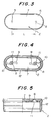
- Fig. 1 is a partially sectional schematic side view of a preferred embodiment of the invention, showing only a principal portion thereof;
- Fig. 2 is a partially sectional schematic front view of the embodiment of Fig. 1;
- Fig. 3 is an enlarged schematic front view of the nozzle tip of the embodiment of Fig. 1;
- Fig. 4 is a view similar to Fig. 3, but showing the rear side of the nozzle tip;
- Fig. 5 is a partially sectional schematic plan view of a half portion of the nozzle tip of Fig. 3.
- Figs. 1 through 5 illustrate an embodiment of spray container for spraying a medicinal liquid to a mucous membrane of a throat in accordance with the present invention. The spray container is generally denoted by reference numeral 1 and comprises a
spray head 3 provided with anozzle tip 2 and a containermain body 4 for storing a medicinal liquid. The spray container includes a pumping mechanism. When thespray head 3 provided with thenozzle tip 2 is depressed by a finger along the direction indicated by arrow X, the medicinal liquid in the containermain body 4 is pumped up from the containermain body 4 and injected through a pair ofinjection ports nozzle tip 2 toward the mucous membrane of the throat. Since the hydrodynamics or the pumping mechanism of this spray container is same as that of any known conventional spray containers, it will not be specifically described any further nor illustrated in the accompanying drawings. - In the illustrated embodiment, the
spray head 3 of of the spray container 1 for spraying the medicinal liquid comprises a nozzlemain body 6 and anozzle tip 2. The nozzle tip comprises anelliptical front panel 7 and aperipheral wall 12. Theelliptical front panel 7 is provided with theinjection ports injection ports elliptical front panel 7 and separated from each other by distance L as shown in Figs. 3, 4 and 5. - As seen from Figs. 4 and 5, the
front panel 7 is provided at a rear side thereof with a pair ofnozzle sacks respective injection ports spin grooves nozzle sack 11, so that the medicinal liquid is injected from each of theinjection ports - In Figs. 4 and 5, the
peripheral wall 12 of thenozzle tip 2 is used for rigidly and engagedly fitting thenozzle tip 2 into a front end of a medicinalliquid flow path 13 of thespray head 3. - The spray container 1 may be made of synthetic resin.
- In an experimental example of the present invention, the nozzle tip provided with a pair of
injection ports - The diameter of the injection port and the distance L are not limited to the above described experimental example.
- While a nozzle tip according to the invention can remarkably increase the coverage of sprayed medicinal liquid by single spraying action, the amount of medicinal liquid consumed in the spraying action is substantially same as the amount consumed by a comparable conventional nozzle tip, because the diameter of the injection ports can be reduced to about 60% of that of a conventional injection port.
- According to the present invention, a remarkably large area of the mucous membrane of the throat can be covered by medicinal liquid with a single spraying action by providing a pair of injection ports on the nozzle tip, so that the entire surface of the mucous membrane of the throat can be covered by liquid with a significantly reduced number of spraying actions as compared with the case of using a conventional spray container and consequently the amount of medicinal liquid that is swallowed down by the subject can be significantly reduced.
- Additionally, a desired profile of injected medicinal liquid and a desired coverage of medicinal liquid on the mucous membrane of the throat can be obtained by appropriately selecting the diameter of the injection ports and the distance between the injection ports.
Claims (5)
- A spray container (1) for spraying a medicinal liquid to a mucous membrane of a throat, comprising
a spray head (3), a pumping mechanism and a container main body (4),
the spray head (3) having a nozzle tip (2), and
the nozzle tip (2) being provided with a pair of injection ports (5,8). - A spray container (1) according to claim 1, wherein
the nozzle tip (2) comprises a front panel (7) and a peripheral wall (12), and
the front panel (7) is provided with the injection ports (5,8). - A spray container (1) according to claim 2, wherein
a rear surface of the front panel (7) is provided with nozzle sacks (11), and
spin grooves (9,10) are formed at an outer periphery of each of the nozzle sacks (11) so that medicinal liquid is injected from each of the injection ports (5,8) as a spiral vortex. - A spray container (1) according to claim 1, wherein the injection ports (5,8) are horizontally juxtaposed.
- A spray container (1) according to claim 1, wherein the spray container (1) comprises a plastics resin.
Applications Claiming Priority (3)
| Application Number | Priority Date | Filing Date | Title |
|---|---|---|---|
| JP7475593 | 1993-12-28 | ||
| JP074755U JPH0739846U (en) | 1993-12-28 | 1993-12-28 | Chemical spray container for throat mucosa |
| JP74755/93 | 1993-12-28 |
Publications (3)
| Publication Number | Publication Date |
|---|---|
| EP0661069A2 true EP0661069A2 (en) | 1995-07-05 |
| EP0661069A3 EP0661069A3 (en) | 1995-09-13 |
| EP0661069B1 EP0661069B1 (en) | 1999-06-23 |
Family
ID=13556412
Family Applications (1)
| Application Number | Title | Priority Date | Filing Date |
|---|---|---|---|
| EP94309812A Expired - Lifetime EP0661069B1 (en) | 1993-12-28 | 1994-12-23 | Spray container for spraying medicinal liquid to mucous membrane of throat |
Country Status (6)
| Country | Link |
|---|---|
| EP (1) | EP0661069B1 (en) |
| JP (1) | JPH0739846U (en) |
| AT (1) | ATE181512T1 (en) |
| CA (1) | CA2139087C (en) |
| DE (1) | DE69419239T2 (en) |
| ES (1) | ES2133500T3 (en) |
Cited By (6)
| Publication number | Priority date | Publication date | Assignee | Title |
|---|---|---|---|---|
| WO2016110641A1 (en) * | 2015-01-09 | 2016-07-14 | L'oreal | Dispensing head having a non-ejectable nozzle |
| FR3031507A1 (en) * | 2015-01-09 | 2016-07-15 | Oreal | DISTRIBUTION HEAD WITH AN EXTENDED HIGHLIGHT |
| FR3031508A1 (en) * | 2015-01-09 | 2016-07-15 | Oreal | HEAD DISTRIBUTION HEAD |
| FR3031505A1 (en) * | 2015-01-09 | 2016-07-15 | Oreal | HEAD OF DISTRIBUTION WITH ALIGNED ORIFICES |
| CN106163672A (en) * | 2014-03-24 | 2016-11-23 | Dlh鲍尔斯公司 | For producing the swirl nozzle assembly with the improvement that efficient mechanical is broken up of uniform spray of small |
| EP4230376A3 (en) * | 2022-01-26 | 2023-09-27 | Aero Pump GmbH | Multibeam hollow cone nozzle |
Family Cites Families (6)
| Publication number | Priority date | Publication date | Assignee | Title |
|---|---|---|---|---|
| GB2005147B (en) * | 1977-09-15 | 1982-03-10 | Rolls Royce | Fluid operated nozzles for generation of vibrations in liquid |
| US4456175A (en) * | 1981-12-03 | 1984-06-26 | Dnepropetrovsky Khimiko-Tekhnologichesky Institut Imeni F. E. Dzerzhinskogo | Nozzle assembly for liquid spraying in coke oven ascension pipe |
| US5002214A (en) * | 1989-12-26 | 1991-03-26 | Caranci Mark W | Medical spray container carrying case |
| FR2671329B1 (en) * | 1991-01-07 | 1993-03-19 | Valois | MULTI-JET PUSH-BUTTON WITH CLOSURE. |
| JP3033252B2 (en) * | 1991-05-23 | 2000-04-17 | いすゞ自動車株式会社 | Method of manufacturing injection nozzle |
| FR2691383B1 (en) * | 1992-05-21 | 1994-08-19 | Oreal | Push button intended to be mounted on a valve or a pump fitted to a dispenser, and dispenser comprising such a push button. |
-
1993
- 1993-12-28 JP JP074755U patent/JPH0739846U/en active Pending
-
1994
- 1994-12-23 DE DE69419239T patent/DE69419239T2/en not_active Expired - Fee Related
- 1994-12-23 AT AT94309812T patent/ATE181512T1/en not_active IP Right Cessation
- 1994-12-23 ES ES94309812T patent/ES2133500T3/en not_active Expired - Lifetime
- 1994-12-23 CA CA002139087A patent/CA2139087C/en not_active Expired - Fee Related
- 1994-12-23 EP EP94309812A patent/EP0661069B1/en not_active Expired - Lifetime
Cited By (8)
| Publication number | Priority date | Publication date | Assignee | Title |
|---|---|---|---|---|
| CN106163672A (en) * | 2014-03-24 | 2016-11-23 | Dlh鲍尔斯公司 | For producing the swirl nozzle assembly with the improvement that efficient mechanical is broken up of uniform spray of small |
| US10130960B2 (en) | 2014-03-24 | 2018-11-20 | Dlhbowles, Inc. | Swirl nozzle assemblies with high efficiency mechanical break up for generating mist sprays of uniform small droplets |
| CN106163672B (en) * | 2014-03-24 | 2020-03-03 | Dlh鲍尔斯公司 | Improved swozzle assembly with high efficiency mechanical break-up for producing uniform small droplet spray |
| WO2016110641A1 (en) * | 2015-01-09 | 2016-07-14 | L'oreal | Dispensing head having a non-ejectable nozzle |
| FR3031507A1 (en) * | 2015-01-09 | 2016-07-15 | Oreal | DISTRIBUTION HEAD WITH AN EXTENDED HIGHLIGHT |
| FR3031508A1 (en) * | 2015-01-09 | 2016-07-15 | Oreal | HEAD DISTRIBUTION HEAD |
| FR3031505A1 (en) * | 2015-01-09 | 2016-07-15 | Oreal | HEAD OF DISTRIBUTION WITH ALIGNED ORIFICES |
| EP4230376A3 (en) * | 2022-01-26 | 2023-09-27 | Aero Pump GmbH | Multibeam hollow cone nozzle |
Also Published As
| Publication number | Publication date |
|---|---|
| EP0661069B1 (en) | 1999-06-23 |
| ATE181512T1 (en) | 1999-07-15 |
| CA2139087A1 (en) | 1995-06-29 |
| DE69419239D1 (en) | 1999-07-29 |
| EP0661069A3 (en) | 1995-09-13 |
| CA2139087C (en) | 2000-02-15 |
| ES2133500T3 (en) | 1999-09-16 |
| JPH0739846U (en) | 1995-07-18 |
| DE69419239T2 (en) | 1999-11-04 |
Similar Documents
| Publication | Publication Date | Title |
|---|---|---|
| EP0585379B1 (en) | Aerosol inhalation device | |
| US5231983A (en) | Method of and apparatus for the aerosol administration of medication | |
| USD332652S (en) | Trigger sprayer | |
| USD354226S (en) | Trigger sprayer | |
| CA2310224A1 (en) | Inhalation device | |
| USD356249S (en) | Spray nozzle and actuator | |
| USD367815S (en) | Dispensing bottle with external cartridge | |
| EP0117898A3 (en) | Trigger-type sprayer | |
| MX9602315A (en) | Medicinal liquids double distributor. | |
| JP2017077478A (en) | Atomizer for nasal therapy | |
| GR3030323T3 (en) | Inhalation device. | |
| JPH11189282A (en) | System and method for one-way spray/aerosol tip | |
| CA2231868A1 (en) | Pen injector with cartridge loading mechanism | |
| PL316261A1 (en) | Self-contained counter for metering doses administered by mean of an inhaler | |
| EP0661069A2 (en) | Spray container for spraying medicinal liquid to mucous membrane of throat | |
| US20060137683A1 (en) | Nozzle | |
| GR3033720T3 (en) | Tamper-deterrent nozzle for pump dispensers | |
| US3517667A (en) | Aerosolized inhalator dispenser | |
| EP0878239A2 (en) | Domed air cap | |
| AU659365B1 (en) | Medicine feeder for babies | |
| US6690904B2 (en) | Developer container | |
| JPS6343674A (en) | Inhalation mask of nebulizer | |
| EP0251687A3 (en) | Electrostatic spray head | |
| USD346202S (en) | Spray tube for an oscillating sprinkler | |
| JPS5556852A (en) | Liquid spray apparatus |
Legal Events
| Date | Code | Title | Description |
|---|---|---|---|
| PUAI | Public reference made under article 153(3) epc to a published international application that has entered the european phase |
Free format text: ORIGINAL CODE: 0009012 |
|
| AK | Designated contracting states |
Kind code of ref document: A2 Designated state(s): AT CH DE ES FR GB IT LI |
|
| PUAL | Search report despatched |
Free format text: ORIGINAL CODE: 0009013 |
|
| AK | Designated contracting states |
Kind code of ref document: A3 Designated state(s): AT CH DE ES FR GB IT LI |
|
| 17P | Request for examination filed |
Effective date: 19951211 |
|
| 17Q | First examination report despatched |
Effective date: 19970813 |
|
| GRAG | Despatch of communication of intention to grant |
Free format text: ORIGINAL CODE: EPIDOS AGRA |
|
| GRAG | Despatch of communication of intention to grant |
Free format text: ORIGINAL CODE: EPIDOS AGRA |
|
| GRAH | Despatch of communication of intention to grant a patent |
Free format text: ORIGINAL CODE: EPIDOS IGRA |
|
| GRAH | Despatch of communication of intention to grant a patent |
Free format text: ORIGINAL CODE: EPIDOS IGRA |
|
| GRAA | (expected) grant |
Free format text: ORIGINAL CODE: 0009210 |
|
| AK | Designated contracting states |
Kind code of ref document: B1 Designated state(s): AT CH DE ES FR GB IT LI |
|
| REF | Corresponds to: |
Ref document number: 181512 Country of ref document: AT Date of ref document: 19990715 Kind code of ref document: T |
|
| ITF | It: translation for a ep patent filed | ||
| REG | Reference to a national code |
Ref country code: CH Ref legal event code: EP |
|
| REF | Corresponds to: |
Ref document number: 69419239 Country of ref document: DE Date of ref document: 19990729 |
|
| ET | Fr: translation filed | ||
| REG | Reference to a national code |
Ref country code: ES Ref legal event code: FG2A Ref document number: 2133500 Country of ref document: ES Kind code of ref document: T3 |
|
| REG | Reference to a national code |
Ref country code: CH Ref legal event code: NV Representative=s name: KIRKER & CIE SA |
|
| PLBE | No opposition filed within time limit |
Free format text: ORIGINAL CODE: 0009261 |
|
| STAA | Information on the status of an ep patent application or granted ep patent |
Free format text: STATUS: NO OPPOSITION FILED WITHIN TIME LIMIT |
|
| 26N | No opposition filed | ||
| REG | Reference to a national code |
Ref country code: GB Ref legal event code: IF02 |
|
| PGFP | Annual fee paid to national office [announced via postgrant information from national office to epo] |
Ref country code: ES Payment date: 20071226 Year of fee payment: 14 |
|
| PGFP | Annual fee paid to national office [announced via postgrant information from national office to epo] |
Ref country code: AT Payment date: 20071212 Year of fee payment: 14 Ref country code: CH Payment date: 20071213 Year of fee payment: 14 |
|
| PGFP | Annual fee paid to national office [announced via postgrant information from national office to epo] |
Ref country code: GB Payment date: 20071219 Year of fee payment: 14 Ref country code: FR Payment date: 20071210 Year of fee payment: 14 |
|
| PGFP | Annual fee paid to national office [announced via postgrant information from national office to epo] |
Ref country code: IT Payment date: 20071229 Year of fee payment: 14 Ref country code: DE Payment date: 20071220 Year of fee payment: 14 |
|
| REG | Reference to a national code |
Ref country code: CH Ref legal event code: PL |
|
| GBPC | Gb: european patent ceased through non-payment of renewal fee |
Effective date: 20081223 |
|
| PG25 | Lapsed in a contracting state [announced via postgrant information from national office to epo] |
Ref country code: AT Free format text: LAPSE BECAUSE OF NON-PAYMENT OF DUE FEES Effective date: 20081223 |
|
| REG | Reference to a national code |
Ref country code: FR Ref legal event code: ST Effective date: 20090831 |
|
| PG25 | Lapsed in a contracting state [announced via postgrant information from national office to epo] |
Ref country code: LI Free format text: LAPSE BECAUSE OF NON-PAYMENT OF DUE FEES Effective date: 20081231 Ref country code: DE Free format text: LAPSE BECAUSE OF NON-PAYMENT OF DUE FEES Effective date: 20090701 Ref country code: CH Free format text: LAPSE BECAUSE OF NON-PAYMENT OF DUE FEES Effective date: 20081231 |
|
| PG25 | Lapsed in a contracting state [announced via postgrant information from national office to epo] |
Ref country code: GB Free format text: LAPSE BECAUSE OF NON-PAYMENT OF DUE FEES Effective date: 20081223 |
|
| REG | Reference to a national code |
Ref country code: ES Ref legal event code: FD2A Effective date: 20081224 |
|
| PG25 | Lapsed in a contracting state [announced via postgrant information from national office to epo] |
Ref country code: FR Free format text: LAPSE BECAUSE OF NON-PAYMENT OF DUE FEES Effective date: 20081231 Ref country code: ES Free format text: LAPSE BECAUSE OF NON-PAYMENT OF DUE FEES Effective date: 20081224 |
|
| PG25 | Lapsed in a contracting state [announced via postgrant information from national office to epo] |
Ref country code: IT Free format text: LAPSE BECAUSE OF NON-PAYMENT OF DUE FEES Effective date: 20081223 |