EP0660567B1 - Lokales Netzwerk - Google Patents
Lokales Netzwerk Download PDFInfo
- Publication number
- EP0660567B1 EP0660567B1 EP94203676A EP94203676A EP0660567B1 EP 0660567 B1 EP0660567 B1 EP 0660567B1 EP 94203676 A EP94203676 A EP 94203676A EP 94203676 A EP94203676 A EP 94203676A EP 0660567 B1 EP0660567 B1 EP 0660567B1
- Authority
- EP
- European Patent Office
- Prior art keywords
- network interface
- radio
- cells
- network
- station
- Prior art date
- Legal status (The legal status is an assumption and is not a legal conclusion. Google has not performed a legal analysis and makes no representation as to the accuracy of the status listed.)
- Expired - Lifetime
Links
- 239000000872 buffer Substances 0.000 claims description 60
- 230000005540 biological transmission Effects 0.000 claims description 33
- 238000012546 transfer Methods 0.000 claims description 12
- 230000003139 buffering effect Effects 0.000 claims 1
- 210000004027 cell Anatomy 0.000 description 109
- 230000008878 coupling Effects 0.000 description 20
- 238000010168 coupling process Methods 0.000 description 20
- 238000005859 coupling reaction Methods 0.000 description 20
- 238000011156 evaluation Methods 0.000 description 13
- 230000015654 memory Effects 0.000 description 10
- 238000010586 diagram Methods 0.000 description 5
- 238000000034 method Methods 0.000 description 4
- 238000012545 processing Methods 0.000 description 3
- 238000001514 detection method Methods 0.000 description 2
- 238000011161 development Methods 0.000 description 2
- 238000004458 analytical method Methods 0.000 description 1
- 238000003491 array Methods 0.000 description 1
- 238000004364 calculation method Methods 0.000 description 1
- 230000015556 catabolic process Effects 0.000 description 1
- 150000001875 compounds Chemical class 0.000 description 1
- 238000006731 degradation reaction Methods 0.000 description 1
- 230000006870 function Effects 0.000 description 1
- 238000010295 mobile communication Methods 0.000 description 1
- 230000000737 periodic effect Effects 0.000 description 1
- 238000012552 review Methods 0.000 description 1
- 239000007787 solid Substances 0.000 description 1
- 230000005236 sound signal Effects 0.000 description 1
- 210000000352 storage cell Anatomy 0.000 description 1
- 238000012360 testing method Methods 0.000 description 1
Images


Classifications
-
- H—ELECTRICITY
- H04—ELECTRIC COMMUNICATION TECHNIQUE
- H04W—WIRELESS COMMUNICATION NETWORKS
- H04W48/00—Access restriction; Network selection; Access point selection
- H04W48/08—Access restriction or access information delivery, e.g. discovery data delivery
-
- H—ELECTRICITY
- H04—ELECTRIC COMMUNICATION TECHNIQUE
- H04Q—SELECTING
- H04Q11/00—Selecting arrangements for multiplex systems
- H04Q11/04—Selecting arrangements for multiplex systems for time-division multiplexing
- H04Q11/0428—Integrated services digital network, i.e. systems for transmission of different types of digitised signals, e.g. speech, data, telecentral, television signals
- H04Q11/0478—Provisions for broadband connections
-
- H—ELECTRICITY
- H04—ELECTRIC COMMUNICATION TECHNIQUE
- H04L—TRANSMISSION OF DIGITAL INFORMATION, e.g. TELEGRAPHIC COMMUNICATION
- H04L12/00—Data switching networks
- H04L12/54—Store-and-forward switching systems
- H04L12/56—Packet switching systems
- H04L12/5601—Transfer mode dependent, e.g. ATM
- H04L2012/5603—Access techniques
- H04L2012/5604—Medium of transmission, e.g. fibre, cable, radio
- H04L2012/5607—Radio
-
- H—ELECTRICITY
- H04—ELECTRIC COMMUNICATION TECHNIQUE
- H04L—TRANSMISSION OF DIGITAL INFORMATION, e.g. TELEGRAPHIC COMMUNICATION
- H04L12/00—Data switching networks
- H04L12/54—Store-and-forward switching systems
- H04L12/56—Packet switching systems
- H04L12/5601—Transfer mode dependent, e.g. ATM
- H04L2012/5619—Network Node Interface, e.g. tandem connections, transit switching
-
- H—ELECTRICITY
- H04—ELECTRIC COMMUNICATION TECHNIQUE
- H04W—WIRELESS COMMUNICATION NETWORKS
- H04W84/00—Network topologies
- H04W84/02—Hierarchically pre-organised networks, e.g. paging networks, cellular networks, WLAN [Wireless Local Area Network] or WLL [Wireless Local Loop]
- H04W84/10—Small scale networks; Flat hierarchical networks
- H04W84/12—WLAN [Wireless Local Area Networks]
Definitions
- the invention relates to a local area network several network interfaces, each with a Station are coupled and the interchangeable are provided by data.
- a local network is from the publication "Without Chips do not care - standard chips for ATM systems are in the Coming "by Bernd Reder, electronics 1/1993, pages 66 to 75, known. In this review article, the current State in the development of integrated circuits discussed for applications in local area networks, that work in asynchronous transfer mode (ATM). Each station is connected via a network interface connected to the ring terminals of the local network. to Control of the ATM cell stream are in the network interface Coupling devices (switches) used.
- each Cell When using an asynchronous transfer mode in one System will be payload, e.g. Telephone, picture or sound signals, in blocks of fixed length over arrays sent for digital signal processing.
- payload e.g. Telephone, picture or sound signals
- a cell As a block Fixed length, a cell is called, which is a predetermined Number of bytes (e.g., 53 bytes).
- each Cell consists of a header field with a length of, for example 5 bytes and an information field in which the User information is housed, with a length of for example, 48 bytes.
- Path identifiers data for error detection and data for Control information available.
- Bundle IDs and connection IDs are Bundle IDs to understand.
- the Connection identifier also known as VCI (Virtual Channel Identifier) contains the information about the Destination of the cell in the system. To submit a cell is based the connection identifier provided a virtual channel. Usually a VCI is changed after reaching an exchange. A bunch multiple virtual channels is called a virtual path. A virtual path is indicated by the bundle identifier. Such a virtual path becomes VPI Called Virtual Path Identifier. Cells are sequentially determined Assigned to time segments. The duration of such a period of time depends on the underlying clock frequency of the transmission component. If no payload is present, empty cells are transferred in such a time period, i.e. Cells without payload. Cells that have a payload include, are referred to as Nutzzellen.
- Radio transmission paths For the transmission of data or the exchange between the Network interfaces of the local network can be wired or a wireless transmission type can be selected.
- the transfer of data via Radio transmission paths is advantageous, for example, when the station is mobile have to be. Under such a station is e.g. a cordless phone, a portable one Personal computer or even a wireless headphones to understand.
- the invention is based on the object of providing a flexible local network create.
- the object is achieved by a local area network according to the features of claim 1 solved.
- the transmission between the individual network interfaces for example via data packets.
- each Network interface reports the radio station, for example, in periodic Distances the size of the information to be transmitted (load information).
- the message is sent to transmit a data signal with a bitrate of 2 Mbit / s is required.
- a packet transmission e.g. communicated the number and size of the packages.
- the radio station determines which radio channel capacity must be made available. So can between two network interfaces, for example, one or more radio channels with a Total capacity of 34 Mbps and one or more radio channels between others Network interfaces of 2 Mbit / s can be assigned. In this case, a frequency or a time-division multiplexing method. It is also conceivable Using the Code Division Multiplex Access (CDMA) method.
- CDMA Code Division Multiplex Access
- the transmission between the individual network interfaces and the Radio station can either have a separate carrier frequency or through Transmission in a time slot using the time division multiplex method done.
- the exchange of data between the network interfaces can be via wired paths or radio transmission paths respectively.
- An increase in flexibility results in a transfer of data via Radio transmission paths.
- a wireless local area network is particular in Households suitable to telephone, screen Speaker audio tuner, TV tuner, CD player, personal computer and couple other devices together. in this connection In a simple way can also be a change of the Site done (flexibility).
- each Network interface If in the local network packets between each Network interfaces are transmitted, is an output buffer arrangement in a network interface to Caching the packets to be sent provided.
- the radio station then receives from the network interfaces Load information about the contents of each output buffer arrangement.
- a special case of packet transfer is asynchronous Transfer mode (ATM), where packets or blocks are firmer Length can be transmitted as cells. Because of the solid Length of the cells results in easier processing.
- ATM asynchronous Transfer mode
- a network interface sends and receives cells and sends load information about the number of to one other network interface to be transmitted cells. This load information is due to the low Information usually not in cells after the transfer asynchronous transfer mode.
- the load distribution can be simplified by the radio station Way controlled when the radio channels time slots a time-division multiplexing frame.
- the radio station for allocating time slots of a time-division multiplex frame for each network interface depending on the number of to another network interface too transmitted cells in the associated output buffer arrangement intended.
- a network interface with of a large load are e.g. three timeslots and one others with a lower load a timeslot from the Radio station assigned. During a time slot can several cells are transmitted.
- a network interface includes a controller for controlling the output buffer arrangement and for determining the number of cells in the output buffer arrangement, a radio transmitting device for transmitting the from the control device contained load information to the radio station and a radio receiving device for forwarding the data received from the radio station to the control device.
- the control device is for generating a Release command provided for the radio transmitting device, so that only during an assigned time slot the Radio transmitting device for transmitting from the output buffer arrangement used cells.
- a coupling device routes the cell current. This is for forwarding the cells received by the radio receiving device, an assigned station cells or the Control device delivered cells to the assigned Station, the control device and / or the radio transmission device intended.
- the coupling device is coupled via feeder lines to an output of the station, an output of the control device and the radio receiving device and via trunk lines to an input of the station, an input of the control device and the radio transmitting device.
- Each trunk is coupled to a transmit buffer of the output buffer arrangement.
- Each transmit buffer is coupled via a respective cell filter with a feeder line.
- a cell filter is provided for checking the address of a cell and forwarding cells with the correct address to the associated transmit buffer.
- a coupling control is used to exchange messages about the forwarded to a transmit buffer cells with a cell filter and at least to release the send buffer.
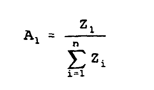
- the base control arrangement calculates a proportion A 1 for a first network interface.
- This portion A 1 is multiplied by the number M of time slots of a time division frame.
- the rounded-up multiplication result indicates the number S 1 of time slots of the time division frame for the first network interface.
- a corrected portion B 1 is calculated.
- the number of time slots for the other network interfaces is determined.
- the distribution of time slots in the time division frame is any.
- the radio station in each case as a bridge link for forwarding the data received from a network interface another network interface is provided.
- this connection can use similar transmission methods and circuits as in the GSM system (Global System for Mobile Communication) be used.
- GSM Global System for Mobile Communication
- An overview of this mobile radio system is found in EP-A2-0 544 457.
- the invention also relates to a network interface and a radio station for a local area network.
- This network interface is linked to a station, is used to exchange data via radio transmission links with neighboring network interfaces and one Radio station and is to send load information the radio station and to receive information about at least one radio channel to be used for the data exchange with the neighboring network interfaces of the radio station provided.
- the radio station for a local Network with several, each coupled to a station Network interfaces for exchanging data via radio transmission paths is to exchange data with the network interfaces via radio transmission paths, for Receiving load information of the network interfaces and depending on the load information for sending the Distribution of radio channels for data exchange between provided the network interfaces.
- Fig. 1 is an overview image of an embodiment a local network with four devices 1 to 4, each consisting of a network interface and one station.
- a station can, for example a telephone, a video telephone, a personal computer, a TV, an audio tuner.
- the Messages or the information provided by the stations or the network interfaces of a device 1 to 4 come after the asynchronous transfer mode using Cells via radio transmission paths between the individual Network interfaces transmitted.
- the network interface The device 1 sends the cells to the network interface the device 2, the network interface the device 2 sends the cells to the network interface the device 3, the network interface of Device 3 sends the cells to the network interface the device 4 and the network interface of the device 4 sends the cells to the network interface of Device 1 (ring traffic).
- a cell contains a header field with, for example, 5 bytes and an information field with, for example, 48 bytes.
- the used in the header of the cell information in particular for addressing and for carrying out Switching functions.
- the radio transmission of the cells between the individual Network interfaces will be time multiplexed carried out.
- For each ring connection are one or several timeslots of a time-division multiplex frame are present. Several cells can be inserted in one time slot.
- the distribution of the time slots controls a radio station 5, also via radio transmission paths with the Network interfaces of the devices 1 to 4 communicates. This is due to the lower amount of information as in the data exchange over the ring connections no cells used.
- the ring traffic is in this case via a first carrier with a first carrier frequency and the traffic with the network interfaces and the radio station 5 via a second carrier with a settled second carrier frequency. It is also possible another time slot for the traffic of the radio station 5 with the network interfaces available too put.
- a network interface 6 and an associated station 7 are shown in more detail in FIG. 2.
- the station 7 is respectively with buffer memories 8 and 9 of the network interface 6 connected.
- the buffer memory 9 supplies Cells from the station 7 to a first evaluation circuit 10 coupled to a route table 11 and evaluates the header field of an incoming cell. Address information in the header of the cell is called Memory address for the first evaluation circuit 10 connected route table 11 is used.
- the under the Memory address stored information in the route table 11 is from the first evaluation circuit 10 for further Processing and forwarding of the cell used. For example, the first evaluation circuit 10 the Copy the cell and add a new address.
- the first evaluation circuit 10 is connected to a coupling device 12 connected to the cell stream in the network interface 6 directs.
- the coupling device 12 with the buffer memory 8, a control device 13, an output buffer arrangement 14 and a second one Evaluation circuit 15 coupled.
- About connections between Control device 13 and coupling device 12 become cells and transmit control information.
- the control device 13, which may be designed as a microprocessor, is used for connection establishment and dismantling and for the control the coupling device 12th
- the coupling device 12 receives cells from the second Evaluation circuit 15, which works the same as the first Evaluation circuit 10 and the one with another route table 16 is connected.
- the route tables 11 and 16 can even with new memory contents via one connection each supplied by the control device 13.
- the buffer memory 8 and the output buffer arrangement 14 receive cells from the coupling device 12 and serve as well as the buffer memory 9 for clock adjustment.
- a radio transmitter modulates the data to be sent to a first Carrier, as for example in the GSM system is carried out.
- the control device 13 controls the Radio transmitting device 17 so that only during one for the Transmission of cells of the network interface 6 certain Timeslot a first carrier with the cells is sent.
- Control information for the load information receives the radio transmitting device 17 via a another line from the control device 13.
- the load information are modulated onto a second carrier.
- a radio receiving device 18 receives data based on a first carrier are modulated and in certain Timeslots are inserted from another network interface and modulated onto a second carrier Control information from the radio station 5.
- the radio receiving device 18 is similar to the known ones from the GSM system.
- the cells received will be after demodulation via a further buffer memory 19, which also serves for clock adjustment, the second evaluation circuit 15 given. Load information would be sent via a another line supplied to the control device 13.
- two types of payload cells are transmitted.
- One received by the second evaluation circuit 15 User cell can on the one hand to the station 7 or on the other to the output buffer assembly 14 from the coupling device 12 will be forwarded.
- a user cell can be deleted in the second evaluation circuit 15 also.
- the coupling device 12 can also be a user cell for Station 7 and at the same time to the output buffer 14th to transfer. A user cell generated by the station 7 only to the output buffer assembly 14 from the coupling device 12 forwarded.
- Control cells supplied by the radio receiving device 18 can be sent to station 7 and / or to the output buffer arrangement 14 be given. In addition, one can Control cell still forwarded to the control device 13 become. Control cells generated by the control device 13 can be generated to the station 7 and / or the output buffer arrangement 14 arrive. The from the station 7 delivered control cells can be used in a self-test be returned to the station 7 again.
- the coupling device 12 is after receiving a cell first evaluated the header of a cell. Is the im Header field not equal to the address of the header Station 7, it is passed to the output buffer 14. Corresponds to the address in the header field of the cell the address of the station 7, so this is the station 7 and / or forwarded to the control device 13. As well it is conceivable that the cell also continues to the output buffer arrangement 14 is given.
- VCI virtual channel identifier
- This information contains after proposals for standardization, the destination of a Cell, indicating a virtual connection.
- VPI virtual path identifier
- the CPI contains Information about the address or the destination.
- the VCI can specify the user-related identifier for a connection, the type of connection and the cell type contain.
- VCI For the CPI are in the header of the cell after current Standardization provisions 8 bit and intended for the VCI 16 bit.
- One bit of the VCI can be used for the specification whether it is a control cell or a user cell is. At least two more bits can be the kind specify the connection. It can be a single connection (unicast-connection), a multicastconnection or a broadcast connection available.
- For a single connection or end-to-end connection there is a virtual connection of one User of a first station with a user of a second station.
- For a multiple connection or point-to-multipoint connection are several users of stations connected with each other.
- In a distribution connection Provides a sending station to all between the sending station and the last receiving station lying stations Cells with the same content in the information field.
- the remaining Bits of the VCI can be used for a user-related identifier to serve for a connection.
- the VCI set in this way and VPI indicate unique connections. Like a connection and degradation in such a local network is performed is e.g. in the German patent application P 43 29 048 described.
- FIG. 3 A block diagram of an embodiment of an in the network interface 6 included coupling device 12 shows FIG. 3.
- a coupling device 12 is For example, in the publication "A Versatile ATM Switch Concept "by U. Killat, W. Kowalk, J. Noll, H.G. Keller, H.J. Reumermann and U. Ziegler, XIII International Switching Symposium, Swiss, Sweden, 27.5. to 1.6.1990, Session A6, Paper # 4, Procceedings Vol IV, Pages 127 to 134, described.
- the coupling device 12 is via a feeder line 20 with the first evaluation circuit 10, via a feeder line 21 with the second Evaluation circuit 15 and a third feeder line 22 coupled to the control device 13. With each feeder line 20, 21 and 22 are each three Cell filters 23 to 31 connected.
- the output of the with the Feeder line 22 connected cell filter 23, the Output of connected to the feeder line 21 cell filter 24 and the output of the feeder line 20 connected cell filters 25 are connected to a transmit buffer 32 coupled.
- the outputs of the cell filters 26 to 28 are with a transmit buffer 33 and the cell filter 29th to 31 coupled to a transmit buffer 34.
- the cell filters 26 and 29 are connected to the feeder line 22, the cell filters 27 and 30 are connected to the feeder line 21 and the cell filters 28 and 31 are connected to the feeder line 20 connected.
- the output of the transmit buffer 32 is over a pickup line 35 to the buffer memory 8, the Output of the transmit buffer 33 via a pickup line 36 with the output buffer arrangement 14 and the output of the Transmit buffer 34 via a pickup line 37 to the control device 13 coupled.
- a cell filter 23 to 31 checks by the address in Header of a cell, whether the cell arrived to the assigned Customer line 35 to 37 should arrive. In a cell filter 23 to 31 is also a temporary storage Cells take place before being assigned to Transmit buffer 32 to 34 arrive. The caching the cells is communicated to a coupling control 39, which the reading order of all cached Determines cells in a cell filter 23 to 31 and which likewise the readout of the cells from the transmission buffers 32 until 34 controls.
- the control device 13 receives load information (Number of cells) from the output buffer array 14. This load information is received from the control device 13 via the radio transmitting device 17 to the radio station. 5 passed, which the control device 13 after receipt all load information from all network interfaces the distribution of time slots announces. The Control device 13 receives via the radio receiving device 18 from the radio station 5 the information of the distribution the time slots. This forms the control device 13, a release command for the radio transmitting device 17, after receiving the release command, cells from the output buffer array 14 and read on a first Carrier modulated.
- load information Numberer of cells
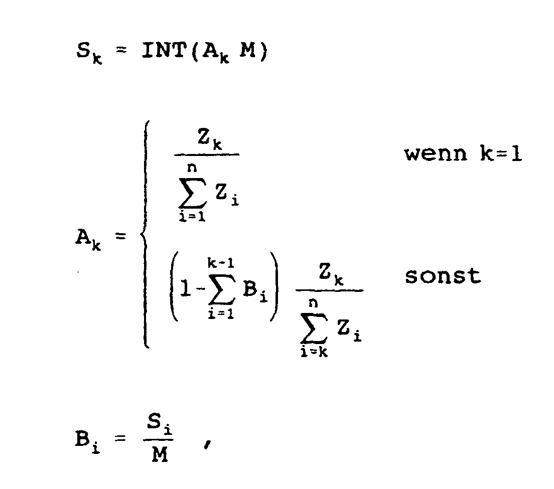
- the base control device 42 calculates from the received Load information of all network interfaces the load distribution.
- Each network interface contains in the output buffer arrangement 14 Z k cells.
- Each multiplex frame has M timeslots.
- the proportion A 1 is calculated on the total time slots for a first network interface according to the following formula:
- S 1 INT ( A 1 M)
- S 2 INT ( A 2 M)
- the base control device 42 calculates the distribution of Time slots for each new time division frame.
- FIG. 5 An example of the distribution of 8 timeslots of a time-division multiplex frame T R is shown in FIG. 5.
- a network interface A sends cells to a network interface B
- the network interface B sends cells to a network interface C
- the network interface C sends cells to a network interface D
- the network interface D sends cells to the network interface A.
- the base control device 42 assigns two timeslots to the network interface A, one time slot to the network interface B, three timeslots to the network interface C and two timeslots to the network interface D.
- the distribution of the time slots in this example takes place uniformly over the time-division multiplex frame T R.
- Fig. 6 is another embodiment of a shown local network. This contains four devices 43 to 46 with a network interface and a assigned station. A radio station 47 is used here not just to calculate the time slot distribution but also as a bridge link. Cells are not directly from network interface to network interface but via the radio station 47. Such an embodiment Can many components of a GSM system use.
Landscapes
- Engineering & Computer Science (AREA)
- Computer Networks & Wireless Communication (AREA)
- Computer Security & Cryptography (AREA)
- Signal Processing (AREA)
- Mobile Radio Communication Systems (AREA)
- Data Exchanges In Wide-Area Networks (AREA)
- Small-Scale Networks (AREA)
Description
Die Koppelvorrichtung ist über Zubringerleitungen mit einem Ausgang der Station, einem Ausgang der Steuervorrichtung und der Funkempfangsvorrichtung und über Abnehmerleitungen mit einem Eingang der Station, einem Eingang der Steuervorrichtung und der Funksendevorrichtung gekoppelt. Jede Abnehmerleitung ist mit einem Sendepuffer der Ausgangspufferanordnung gekoppelt. Jedes Sendepuffer ist über jeweils ein Zellenfilter mit einer Zubringerleitung gekoppelt. Ein Zellenfilter ist zur Überprüfung der Adresse einer Zelle und zur Weiterleitung von Zellen mit korrekter Adresse an den zugeordneten Sendepuffer vorgesehen. Eine Koppelsteuerung dient zum Austausch von Meldungen über die an ein Sendepuffer weitergeleiteten Zellen mit einem Zellenfilter und wenigstens zur Freigabe der Sendepuffer.
- zum Empfang der Anzahl Zk der in einer Ausgangspufferanordnung einer Netzwerkschnittstelle zwischengespeicherten, für die Zuführung zu einer anderen Netzwerkschnittstelle vorgesehenen Zellen,
- zur Berechnung der Anzahl Sk von Zeitschlitzen eines
Zeitmultiplexrahmens für eine Netzwerkschnittstelle
mit den Formeln:
wobei INT eine Rundungsoperation, M die Anzahl der Zeitschlitze eines Zeitmultiplexrahmens, n die Anzahl der Netzwerkschnittstellen, k=1,2,...,n und i=1,2,...,n-1 ist, und
- zur Verteilung der Zeitschlitze für jede Netzwerkschnittstelle vorgesehen.
- Fig. 1
- ein Übersichtsschaltbild eines lokalen, nach dem asynchronen Transfermodus arbeitenden Netzwerkes, bei dem ein Datenaustausch über Funkübertragungswege erfolgt,
- Fig. 2
- ein Blockschaltbild einer in dem lokalen Netzwerk verwendeten Netzwerkschnittstelle mit einer zugeordneten Station,
- Fig.3
- eine schematisch in einer Netzwerkschnittstelle verwendete Koppelvorrichtung,
- Fig. 4
- ein Blockschaltbild einer in dem lokalen Netzwerk verwendeten Funkstation,
- Fig. 5
- einen schematisch skizzierten Zeitmultiplexrahmen zur Erläuterung der Funkübertragung von Daten zwischen den Netzwerkschnittstellen und
- Fig. 6
- ein Übersichtsbild über eine weitere Ausführungsform eines lokalen Netzwerkes.


Claims (11)
- Lokales Netzwerk mit mehreren Netzwerkschnittstellen (6), die jeweils mit einer Station (7) gekoppelt sind und die untereinander zum Austausch von Daten vorgesehen sind, und mit einem Verteilmittel (5), daszum Austausch von Daten mit den Netzwerkschnittstellen (6),zum Empfang von Lastinformationen der Netzwerkschnittstellen (6) undin Abhängigkeit der Lastinformationen zur Ermittlung vorgesehen ist, welche der mehreren Kanalkapazitäten den Netzwerkschnittstellen zur Verfügung gestellt wird, und zur Verteilung der Kanäle für den Datenaustausch zwischen den Netzwerkschnittstellen (6) vorgesehen ist.
- Lokales Netzwerk nach Anspruch 1,
dadurch gekennzeichnet, daß die Netzwerkschnittstellen (6) jeweils zum Austausch von Daten über Funkübertragungswege vorgesehen sind und
daß das Verteilmittel als Funkstation (5) ausgebildet ist, die zum Austausch von Daten mit den Netzwerkschnittstellen (6) über Funkübertragungswege und zur Sendung der Verteilung von Funkkanälen für den Datenaustausch zwischen den Netzwerkschnittstellen (6) vorgesehen ist. - Lokales Netzwerk nach Anspruch 2,
dadurch gekennzeichnet, daß eine Netzwerkschnittstelle (6)zur Sendung und zum Empfang von Daten enthaltenen Paketen vorgesehen ist,eine Ausgangspufferanordnung (14) zur Zwischenspeicherung der zu sendenden Pakete enthält undzur Sendung von Lastinformationen über den Inhalt der Ausgangspufferanordnung (14) an die Funkstation (5) vorgesehen ist. - Lokales Netzwerk nach Anspruch 3,
dadurch gekennzeichnet, daß eine Netzwerkschnittstelle (6)zur Sendung und zum Empfang von Daten enthaltenen, nach dem asynchronen Transfermodus, ATM, gebildeten Zellen undzur Sendung von Lastinformationen über die Anzahl der zu einer anderen Netzwerkschnittstelle (6) zu übertragenen Zellen vorgesehen ist. - Lokales Netzwerk nach Anspruch 4,
dadurch gekennzeichnet, daß die Funkstation (5) zur Zuweisung von Zeitschlitzen eines Zeitmultiplexrahmens für jede Netzwerkschnittstelle (6) in Abhängigkeit von der Anzahl der zu einer anderen Netzwerkschnittstelle (6) zu übertragenen Zellen in der zugeordneten Ausgangspufferanordnung (14) vorgesehen ist. - Lokales Netzwerk nach Anspruch 5,
dadurch gekennzeichnet, daß eine Netzwerkschnittstelle (6)daß die Steuervorrichtung (13) zur Erzeugung eines Freigabebefehls für die Funksendevorrichtung (17) vorgesehen ist, so daß nur während eines zugewiesenen Zeitschlitzes die Funksendevorrichtung (17) zur Sendung von von der Ausgangspufferanordnung (14) abgegebenen Zellen dient.eine Steuervorrichtung (13) zur Steuerung der Ausgangspufferanordnung (14) und zur Bestimmung der Anzahl der Zellen in der Ausgangspufferanordnung (14),eine Funksendevorrichtung (17) zur Sendung der von der Steuervorrichtung (13) enthaltenen Lastinformationen an die Funkstation (5) undeine Funkempfangsvorrichtung (18) zur Weiterleitung der von der Funkstation (5) empfangenen Daten an die Steuervorrichtung (13) enthält und - Lokales Netzwerk nach Anspruch 6,
dadurch gekennzeichnet, daß eine Netzwerkschnittstelle (6) eine Koppelvorrichtung (12) enthält, die zur Weiterleitung der von der Funkempfangsvorrichtung (18) empfangenen Zellen, einer zugeordneten Station (7) abgegebenen Zellen oder der Steuervorrichtung (13) abgegebenen Zellen zu der zugeordneten Station (7), der Steuervorrichtung (13) und/oder der Funksendevorrichtung (17) vorgesehen ist. - Lokales Netzwerk nach Anspruch 7,
dadurch gekennzeichnet, daß die Koppelvorrichtung (12) über Zubringerleitungen (20 bis 22) mit einem Ausgang der Station (7), einem Ausgang der Steuervorrichtung (13) und der Funkempfangsvorrichtung (18) und über Abnehmerleitungen (35 bis 37) mit einem Eingang der Station (7), einem Eingang der Steuervorrichtung (13) und der Funksendevorrichtung (17) gekoppelt ist,
daß jede Abnehmerleitung (35 bis 37) mit einem Sendepuffer (32 bis 34) gekoppelt ist,
daß jedes Sendepuffer (32 bis 34) über jeweils ein Zellenfilter (23 bis 31) mit einer Zubringerleitung (20 bis 22) gekoppelt ist,
daß ein Zellenfilter (23 bis 31) zur Überprüfung der Adresse einer Zelle und zur Weiterleitung von Zellen mit korrekter Adresse an den zugeordneten Sendepuffer (32 bis 34) vorgesehen ist und
daß eine Koppelsteuerung (39) zum Austausch von Meldungen über die an ein Sendepuffer (32 bis 34) weitergeleitete Zelle mit einem Zellenfilter (23 bis 31) und zur Freigabe der Sendepuffer (32 bis 34) vorgesehen ist. - Lokales Netzwerk nach einem der Ansprüche 5 bis 8,
dadurch gekennzeichnet, daß die Funkstation (5) eine Basissteueranordnung (42) enthält, die in jedem Zeitmultiplexrahmenzum Empfang der Anzahl Zk der in einer Ausgangspufferanordnung (14) einer Netzwerkschnittstelle (6) zwischengespeicherten, für die Zuführung zu einer anderen Netzwerkschnittstelle (6) vorgesehenen Zellen,zur Berechnung der Anzahl Sk von Zeitschlitzen eines Zeitmultiplexrahmens für eine Netzwerkschnittstelle (6) mit den Formeln:wobei INT eine Rundungsoperation, M die Anzahl der Zeitschlitze eines Zeitmultiplexrahmens, n die Anzahl der Netzwerkschnittstellen (6), k=1,2,...,n und i=1,2,...,n-1 ist, und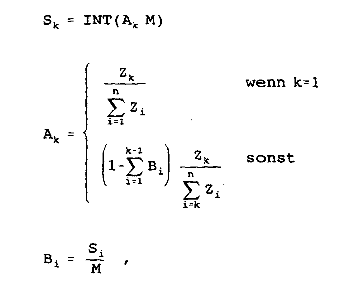 zur Verteilung der Zeitschlitze für jede Netzwerkschnittstelle (6) vorgesehen ist.
 - Lokales Netzwerk nach einem der Ansprüche 2 bis 9,
dadurch gekennzeichnet, daß die Funkstation (47) jeweils als Brückenglied zur Weiterleitung der von einer Netzwerkschnittstelle (6) empfangenen Daten zu einer anderen Netzwerkschnittstelle (6) vorgesehen ist. - Funkstation (5) für ein lokales Netzwerk mit mehreren, jeweils mit einer Station (7) gekoppelten Netzwerkschnittstellen (6) zum Austausch von Daten über Funkübertragungswege, diezum Austausch von Daten mit den Netzwerkschnittstellen (6) über Funkübertragungswege,zum Empfang von Lastinformationen der Netzwerkschnittstellen (6) undin Abhängigkeit der Lastinformationen zur Ermittlung vorgesehen ist, welche der mehreren Kanalkapazitäten den Netzwerkschnittstellen zur Verfügung gestellt wird, und zur Verteilung der Kanäle für den Datenaustausch zwischen den Netzwerkschnittstellen (6) vorgesehen ist.
Applications Claiming Priority (2)
| Application Number | Priority Date | Filing Date | Title |
|---|---|---|---|
| DE4343839A DE4343839A1 (de) | 1993-12-22 | 1993-12-22 | Lokales Netzwerk mit einem Datenaustausch über Funkübertragungswege |
| DE4343839 | 1993-12-22 |
Publications (3)
| Publication Number | Publication Date |
|---|---|
| EP0660567A2 EP0660567A2 (de) | 1995-06-28 |
| EP0660567A3 EP0660567A3 (de) | 1996-08-28 |
| EP0660567B1 true EP0660567B1 (de) | 2005-02-23 |
Family
ID=6505772
Family Applications (1)
| Application Number | Title | Priority Date | Filing Date |
|---|---|---|---|
| EP94203676A Expired - Lifetime EP0660567B1 (de) | 1993-12-22 | 1994-12-19 | Lokales Netzwerk |
Country Status (4)
| Country | Link |
|---|---|
| US (1) | US5537399A (de) |
| EP (1) | EP0660567B1 (de) |
| JP (1) | JP3758697B2 (de) |
| DE (2) | DE4343839A1 (de) |
Families Citing this family (17)
| Publication number | Priority date | Publication date | Assignee | Title |
|---|---|---|---|---|
| DE19536025C1 (de) * | 1995-09-27 | 1997-02-20 | Siemens Ag | Verfahren und Datenübertragungssystem zum wahlweisen Übertragen eines oder mehrerer Datensignalströme über ein Zeitmultiplex-Übertragungsmedium |
| DE19539259B4 (de) * | 1995-10-21 | 2010-02-04 | Thales Defence Deutschland Gmbh | Funkübertragungssystem mit über einen Funkbus verbundenen Funkvorrichtungen |
| GB2313981B (en) * | 1996-06-06 | 2001-04-18 | Roke Manor Research | Assymetric communications channel for a portable computer |
| DE19636394A1 (de) * | 1996-09-07 | 1998-03-12 | Philips Patentverwaltung | Lokales, nach dem asynchronen Transfermodus arbeitendes Netzwerk in Ringstruktur mit drahtlosen Terminals |
| DE19637026A1 (de) * | 1996-09-12 | 1998-04-02 | Philips Patentverwaltung | Lokales Netzwerk mit zur Funkübertragung vorgesehenen Terminals |
| DE19639845C1 (de) * | 1996-09-27 | 1998-04-02 | Philips Patentverwaltung | Lokales Netzwerk mit Sende- und Empfangsvorrichtung |
| GB2362298B (en) * | 1996-12-06 | 2002-01-02 | Immarsat Ltd | Communication method and apparatus |
| US6038223A (en) * | 1997-10-22 | 2000-03-14 | Telefonaktiebolaget Lm Ericsson (Publ) | Access scheme for packet data in a digital cellular communication system |
| DE19755273A1 (de) | 1997-12-12 | 1999-06-17 | Philips Patentverwaltung | Anordnung zur Bearbeitung von Video-Daten |
| DE69832967D1 (de) * | 1997-12-31 | 2006-02-02 | Koninkl Philips Electronics Nv | Universelle drahtlose informationsinfrastruktur für gebäude |
| DE19801875A1 (de) * | 1998-01-20 | 1999-07-22 | Cit Alcatel | Verfahren zum Einrichten einer Verbindung in einem synchronen digitalen Nachrichtenübertragungsnetz und Netzelement |
| DE19848340A1 (de) * | 1998-10-21 | 2000-04-27 | Philips Corp Intellectual Pty | Lokales Netzwerk mit Brücken-Terminal zur Übertragung von Daten zwischen mehreren Sub-Netzwerken |
| TW566019B (en) * | 2000-01-07 | 2003-12-11 | Wavenewworld Internat Corp Pte | A wireless device for receiving broadcast internet information |
| TWI334289B (en) * | 2003-05-20 | 2010-12-01 | Panasonic Corp | Access control method and system |
| US7508840B2 (en) | 2004-05-28 | 2009-03-24 | Bae Systems Information And Electronic Systems Integration Inc. | Mobile temporary incident area network for local communications interoperability |
| US8665087B2 (en) | 2004-11-10 | 2014-03-04 | Bae Systems Information And Electronic Systems Integration Inc. | Wearable or portable device including sensors and an image input for establishing communications interoperability and situational awareness of events at an incident site |
| US8520700B2 (en) | 2004-11-10 | 2013-08-27 | Bae Systems Information And Electronic Systems Integration Inc. | Device for establishing communications interoperability at an incident site including means for recording crisis incidents |
Family Cites Families (9)
| Publication number | Priority date | Publication date | Assignee | Title |
|---|---|---|---|---|
| DE3424866C2 (de) * | 1984-07-06 | 1986-04-30 | Messerschmitt-Bölkow-Blohm GmbH, 8012 Ottobrunn | Verfahren und Anordnung zur Übertragung von Daten, insbesondere in einem Flugzeug |
| US4870408A (en) * | 1987-04-30 | 1989-09-26 | Motorola, Inc. | Method for dynamically allocating data channels on a trunked communication system |
| AU623808B2 (en) * | 1989-09-19 | 1992-05-21 | Fujitsu Limited | Multiple access system for a communication network |
| US5307348A (en) * | 1990-11-05 | 1994-04-26 | Motorola, Inc. | Scheduling in a communication system |
| CA2078193A1 (en) * | 1991-11-27 | 1993-05-28 | Chinmei Chen Lee | Handover of mobile radio calls between base station systems |
| US5390299A (en) * | 1991-12-27 | 1995-02-14 | Digital Equipment Corporation | System for using three different methods to report buffer memory occupancy information regarding fullness-related and/or packet discard-related information |
| EP0578260B1 (de) * | 1992-07-09 | 1999-10-20 | Nec Corporation | Zellulares mobiles TDMA-Übertragungssystem |
| US5363369A (en) * | 1993-03-31 | 1994-11-08 | At&T Bell Laboratories | System for inter packet community communication |
| DE4329048A1 (de) * | 1993-08-28 | 1995-03-02 | Philips Patentverwaltung | Lokales, nach dem asynchronen Transfermodus (ATM) arbeitendes Netzwerk |
-
1993
- 1993-12-22 DE DE4343839A patent/DE4343839A1/de not_active Withdrawn
-
1994
- 1994-12-19 EP EP94203676A patent/EP0660567B1/de not_active Expired - Lifetime
- 1994-12-19 DE DE59410404T patent/DE59410404D1/de not_active Expired - Lifetime
- 1994-12-21 US US08/360,904 patent/US5537399A/en not_active Expired - Lifetime
- 1994-12-22 JP JP32046894A patent/JP3758697B2/ja not_active Expired - Lifetime
Also Published As
| Publication number | Publication date |
|---|---|
| JPH07212373A (ja) | 1995-08-11 |
| EP0660567A2 (de) | 1995-06-28 |
| DE59410404D1 (de) | 2005-03-31 |
| EP0660567A3 (de) | 1996-08-28 |
| US5537399A (en) | 1996-07-16 |
| JP3758697B2 (ja) | 2006-03-22 |
| DE4343839A1 (de) | 1995-06-29 |
Similar Documents
| Publication | Publication Date | Title |
|---|---|---|
| DE69924732T2 (de) | Quellknoten fuer ein breitbandnetzwerk mit atm zellen | |
| DE69331309T2 (de) | Bandbreitenzuordnung, Übertragungsplanung und Vermeidung von Blockierungen in Breitband Asynchroner-Transfer-Modus Netzwerken | |
| EP0833542B1 (de) | Lokales Netzwerk mit Sende- und Empfangsvorrichtung | |
| DE4329048A1 (de) | Lokales, nach dem asynchronen Transfermodus (ATM) arbeitendes Netzwerk | |
| DE69031438T2 (de) | Kommunikationsprotokoll für statistische Datenmultiplexer in einer Weitbereichsnetzanordnung | |
| EP0660567A2 (de) | Lokales Netzwerk | |
| EP0996257A2 (de) | Netzwerk mit Brücken-Terminal zur Übertragung von Daten zwischen mehreren Sub-Netzwerken | |
| DE69936840T2 (de) | Mobilübertragungssystem mit einer atm-verbindungskonfiguration | |
| DE69636370T2 (de) | Verfahren zum senden von nachrichten innerhalb einer gruppe von untergruppen in einem netzwerk | |
| EP0996258A2 (de) | Lokales Netzwerk mit einem Brücken-Terminal zur Übertragung von Daten zwischen mehreren Sub-Netzwerken und zur Schleifendetektion | |
| EP0831620A2 (de) | Lokales Netzwerk mit zur Funkübertragung vorgesehenen Terminals | |
| EP0862350A2 (de) | System zur leitungsungebundenen Übertragung eines rahmensynchronisierten Signals zwischen einer Feststation und wenigstens einem mobilen Terminal | |
| DE69431859T2 (de) | Burst-Server-Vermittlungssystem und -verfahren | |
| EP0830049A2 (de) | Lokales, nach dem asynchronen Transfermodus arbeitendes Netzwerk in Ringstruktur mit drahtlosen Terminals | |
| DE10023037A1 (de) | Koppelfeld für ein Fernmeldenetz und Verfahren zur Vermittlung in einem Koppelfeld | |
| EP0996259B1 (de) | Automatische Konfigurierung eines Brücken-Terminals zur Uebertragung von Daten zwischen mehreren Sub-Netzwerken in einem lokalen Netzwerk | |
| EP1049294B1 (de) | Netzwerk mit mehreren Netzwerk-clustern zur drahtlosen Übertragung von Paketen | |
| EP0685950A2 (de) | Lokales, nach dem asynchronen Transfermodus (ATM) arbeitendes Netzwerk | |
| EP0614296B1 (de) | Lokales, nach dem asynchronen Transfermodus (ATM) arbeitendes Netzwerk | |
| EP0685949A2 (de) | Paketübermittlungssystem | |
| DE4307174A1 (de) | Lokales Netzwerk | |
| DE19532421C1 (de) | Lokales, nach dem asynchronen Transfermodus (ATM) arbeitendes Netzwerk zur Erzeugung von priorisierten Zellen | |
| EP1139607B1 (de) | Drahtloses Netzwerk mit einem Zeitschlitzsortiermechanismus | |
| DE69422437T2 (de) | ATM-Netz für eine Kommunikationsanlage | |
| DE19747534A1 (de) | Digitales Telekommunikations-System mit DECT-Interface für Fax- und Datenanwendungen |
Legal Events
| Date | Code | Title | Description |
|---|---|---|---|
| PUAI | Public reference made under article 153(3) epc to a published international application that has entered the european phase |
Free format text: ORIGINAL CODE: 0009012 |
|
| AK | Designated contracting states |
Kind code of ref document: A2 Designated state(s): DE FR GB |
|
| PUAL | Search report despatched |
Free format text: ORIGINAL CODE: 0009013 |
|
| AK | Designated contracting states |
Kind code of ref document: A3 Designated state(s): DE FR GB |
|
| 17P | Request for examination filed |
Effective date: 19970228 |
|
| D17P | Request for examination filed (deleted) | ||
| R17P | Request for examination filed (corrected) |
Effective date: 19970228 |
|
| RAP3 | Party data changed (applicant data changed or rights of an application transferred) |
Owner name: KONINKLIJKE PHILIPS ELECTRONICS N.V. Owner name: PHILIPS PATENTVERWALTUNG GMBH |
|
| RAP3 | Party data changed (applicant data changed or rights of an application transferred) |
Owner name: KONINKLIJKE PHILIPS ELECTRONICS N.V. Owner name: PHILIPS CORPORATE INTELLECTUAL PROPERTY GMBH |
|
| RAP1 | Party data changed (applicant data changed or rights of an application transferred) |
Owner name: KONINKLIJKE PHILIPS ELECTRONICS N.V. Owner name: PHILIPS CORPORATE INTELLECTUAL PROPERTY GMBH |
|
| 17Q | First examination report despatched |
Effective date: 20030303 |
|
| RAP1 | Party data changed (applicant data changed or rights of an application transferred) |
Owner name: KONINKLIJKE PHILIPS ELECTRONICS N.V. Owner name: PHILIPS INTELLECTUAL PROPERTY & STANDARDS GMBH |
|
| GRAP | Despatch of communication of intention to grant a patent |
Free format text: ORIGINAL CODE: EPIDOSNIGR1 |
|
| GRAS | Grant fee paid |
Free format text: ORIGINAL CODE: EPIDOSNIGR3 |
|
| GRAA | (expected) grant |
Free format text: ORIGINAL CODE: 0009210 |
|
| AK | Designated contracting states |
Kind code of ref document: B1 Designated state(s): DE FR GB |
|
| REG | Reference to a national code |
Ref country code: GB Ref legal event code: FG4D Free format text: NOT ENGLISH |
|
| REF | Corresponds to: |
Ref document number: 59410404 Country of ref document: DE Date of ref document: 20050331 Kind code of ref document: P |
|
| GBT | Gb: translation of ep patent filed (gb section 77(6)(a)/1977) |
Effective date: 20050606 |
|
| PLBE | No opposition filed within time limit |
Free format text: ORIGINAL CODE: 0009261 |
|
| STAA | Information on the status of an ep patent application or granted ep patent |
Free format text: STATUS: NO OPPOSITION FILED WITHIN TIME LIMIT |
|
| 26N | No opposition filed |
Effective date: 20051124 |
|
| ET | Fr: translation filed | ||
| PGFP | Annual fee paid to national office [announced via postgrant information from national office to epo] |
Ref country code: GB Payment date: 20131227 Year of fee payment: 20 |
|
| PGFP | Annual fee paid to national office [announced via postgrant information from national office to epo] |
Ref country code: DE Payment date: 20140228 Year of fee payment: 20 |
|
| REG | Reference to a national code |
Ref country code: DE Ref legal event code: R081 Ref document number: 59410404 Country of ref document: DE Owner name: PHILIPS DEUTSCHLAND GMBH, DE Free format text: FORMER OWNERS: PHILIPS INTELLECTUAL PROPERTY & STANDARDS GMBH, 20099 HAMBURG, DE; KONINKLIJKE PHILIPS ELECTRONICS N.V., EINDHOVEN, NL Effective date: 20140327 Ref country code: DE Ref legal event code: R081 Ref document number: 59410404 Country of ref document: DE Owner name: KONINKLIJKE PHILIPS N.V., NL Free format text: FORMER OWNERS: PHILIPS INTELLECTUAL PROPERTY & STANDARDS GMBH, 20099 HAMBURG, DE; KONINKLIJKE PHILIPS ELECTRONICS N.V., EINDHOVEN, NL Effective date: 20140327 Ref country code: DE Ref legal event code: R081 Ref document number: 59410404 Country of ref document: DE Owner name: PHILIPS DEUTSCHLAND GMBH, DE Free format text: FORMER OWNER: PHILIPS INTELLECTUAL PROPERTY &, KONINKLIJKE PHILIPS ELECTRONICS, , NL Effective date: 20140327 Ref country code: DE Ref legal event code: R081 Ref document number: 59410404 Country of ref document: DE Owner name: KONINKLIJKE PHILIPS N.V., NL Free format text: FORMER OWNER: PHILIPS INTELLECTUAL PROPERTY &, KONINKLIJKE PHILIPS ELECTRONICS, , NL Effective date: 20140327 |
|
| PGFP | Annual fee paid to national office [announced via postgrant information from national office to epo] |
Ref country code: FR Payment date: 20131230 Year of fee payment: 20 |
|
| REG | Reference to a national code |
Ref country code: DE Ref legal event code: R071 Ref document number: 59410404 Country of ref document: DE |
|
| REG | Reference to a national code |
Ref country code: FR Ref legal event code: CD Owner name: PHILIPS INTELLECTUAL PROPERTY S Effective date: 20141126 Ref country code: FR Ref legal event code: CA Effective date: 20141126 |
|
| REG | Reference to a national code |
Ref country code: GB Ref legal event code: PE20 Expiry date: 20141218 |
|
| PG25 | Lapsed in a contracting state [announced via postgrant information from national office to epo] |
Ref country code: GB Free format text: LAPSE BECAUSE OF EXPIRATION OF PROTECTION Effective date: 20141218 |