EP0660535A2 - Apparatus for uniformly correcting erasure and error of received word by using a common polynomial - Google Patents
Apparatus for uniformly correcting erasure and error of received word by using a common polynomial Download PDFInfo
- Publication number
- EP0660535A2 EP0660535A2 EP94309745A EP94309745A EP0660535A2 EP 0660535 A2 EP0660535 A2 EP 0660535A2 EP 94309745 A EP94309745 A EP 94309745A EP 94309745 A EP94309745 A EP 94309745A EP 0660535 A2 EP0660535 A2 EP 0660535A2
- Authority
- EP
- European Patent Office
- Prior art keywords
- polynomial
- error
- erasure
- product
- generation means
- Prior art date
- Legal status (The legal status is an assumption and is not a legal conclusion. Google has not performed a legal analysis and makes no representation as to the accuracy of the status listed.)
- Granted
Links
- 208000011580 syndromic disease Diseases 0.000 claims abstract description 24
- 230000004069 differentiation Effects 0.000 claims abstract description 21
- 238000010586 diagram Methods 0.000 description 13
- 238000000034 method Methods 0.000 description 7
- 238000004891 communication Methods 0.000 description 6
- 230000006870 function Effects 0.000 description 1
- 230000003287 optical effect Effects 0.000 description 1
Images


Classifications
-
- H—ELECTRICITY
- H03—ELECTRONIC CIRCUITRY
- H03M—CODING; DECODING; CODE CONVERSION IN GENERAL
- H03M13/00—Coding, decoding or code conversion, for error detection or error correction; Coding theory basic assumptions; Coding bounds; Error probability evaluation methods; Channel models; Simulation or testing of codes
- H03M13/03—Error detection or forward error correction by redundancy in data representation, i.e. code words containing more digits than the source words
- H03M13/05—Error detection or forward error correction by redundancy in data representation, i.e. code words containing more digits than the source words using block codes, i.e. a predetermined number of check bits joined to a predetermined number of information bits
- H03M13/13—Linear codes
- H03M13/15—Cyclic codes, i.e. cyclic shifts of codewords produce other codewords, e.g. codes defined by a generator polynomial, Bose-Chaudhuri-Hocquenghem [BCH] codes
- H03M13/151—Cyclic codes, i.e. cyclic shifts of codewords produce other codewords, e.g. codes defined by a generator polynomial, Bose-Chaudhuri-Hocquenghem [BCH] codes using error location or error correction polynomials
Definitions
- the present invention relates to an apparatus for correcting an error occurred in a communication path in a digital communication system or a recording medium in a digital recording system, at a receiving or reading station.
- an error correcting code has been used to correct an error occurred in the communication path or the recording medium at the receiving station.
- an error correcting code Reed-Solomon code (RS code) and BCH code have been well known. Those codes are widely utilized in an optical disk and a satellite communication and encoder and decoder therefor have been implemented in the form of IC.
- the code is defined on a Galois field GF(2 m ) and a primitive element thereof is at ⁇ .
- the encoding is carried out by the following operation.
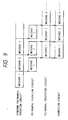
- the syndrome polynomial S(x) is inputted to polynomial operation circuits 4 and 5 and an error locator polynomial ⁇ (x) and a differentiation thereof ⁇ '(x) and an error evaluator polynomial ⁇ (x) are determined in the course of an operation of an Euclidean algorithm. Then, the error locator polynomial ⁇ (x), the differentiation thereof ⁇ '(x) and the error evaluator polynomial ⁇ (x) are inputted to polynomial processing circuits 6a - 6c where x is set to ⁇ i and the formulas thus processed are inputted to a correction circuit 7.
- a memory M is provided as shown in Fig. 8 and it receives the received word in synchronism with the processing of the syndrome polynomial operation circuit 1 and outputs it in synchronism with the processing of the correction circuit 7 to carry out the decoding at a high speed on real time basis.
- 16 errors can be corrected at a rate of 80M bits/sec (bps) on real time basis but it cannot carry out erasure correction.
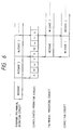
- a decoder for carrying out the decoding operation including the erasure correction (USP 5,325,373) and Fig. 10 shows a block diagram of a configuration principle of the proposal.
- the error evaluator polynomial ⁇ (x) and the error locator polynomial ⁇ (x) which meet the formulas (10) and (11) are determined by separate processing in the course of the Euclidean algorithm to determine a greatest common divisor polynomial (GCD) of x d-1 and M(x).
- GCD centroid polynomial
- the error evaluator polynomial ⁇ ( ⁇ i ), the error locator polynomial ⁇ ( ⁇ i ), the differentiation ⁇ '( ⁇ i ) of the error locator polynomial ⁇ (x), the erasure locator polynomial ⁇ ( ⁇ i ) and the differentiation ⁇ '( ⁇ i ) of the erasure locator polynomial ⁇ (x) are inputted to the correction circuit 7.
- the correction value p i is added to the i-th symbol R i of the received word determined to have the error to correct the error and fill the erasure in order to correct the received word
- the decoding operation including the erasure correction can be carried out by the decoder previously proposed by the present inventors.
- the proposed decoder can carry out the-decoding operation including the erasure correction but a circuit scale of the decoder and a processing time increase and the high speed real time processing as disclosed in USP 4,873,688 is difficult to attain.
- hte present invention unifies the processes of calculating the erasure location and value and the error location and value by using a common polynomial to simplify a circuit for the erasure correction and error correction to attain high speed processing.
- the present invention provides an apparatus for correcting erasure and error of a received word comprising: syndrome polynomial generation means for generating a syndrome polynomial based on the received word; erasure locator polynomial generation means for generating an erasure locator polynomial based on an erasure location; first product polynomial generation means for generating a first product polynomial which is a product of the syndrome polynomial and the erasure locator polynomial; error evaluator polynomial generation means for generating an error evaluator polynomial based on the first product polynomial; second product polynomial generation means for generating a second product polynomial which is a product of the erasure locator polynomial and the error locator polynomial and a differentiation of the second product polynomial; first numeric operation means for producing the value of differentiation of the second product polynomial with a specific dimension; second operation means for producing a value of the error
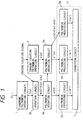
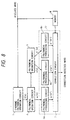
- Fig. 1 shows a block diagram of a configuration principle of a decoder of the present embodiment
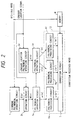
- Fig. 2 shows a block diagram of a configuration of the decoder of the present embodiment
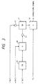
- Fig. 3 shows a block diagram of a main portion of a correction circuit 7 of the present embodiment
- Fig. 4 illustrates an operation of the decoder of the present embodiment.
- the product polynomial operation circuit 3 is eliminated from the decoder shown in Fig. 10, and an operation circuit 2b of the same configuration as that of the erasure locator polynomial operation circuit 2 is provided in place of the product polynomial operation circuit 3.
- the polynomial processing circuit of the correction circuit 12 operates the error evaluator polynomial ⁇ (x)
- the error and erasure locator polynomial ⁇ (x) ⁇ (x) ⁇ (x) and the differentiation ⁇ '(x) of the error and erasure locator polynomial ⁇ (x)
- three error evaluator polynomials 6a, 6f and 6g are provided.
- the configuration of other portions of the present embodiment is identical to that of the decoder of Fig. 10 described above.
- the final result polynomial derived from the formulas (15) and (16) is ⁇ (x) ⁇ e (x).
- ⁇ (X) ⁇ (x) ⁇ (x) is referred to as the error and erasure locator polynomial.
- the polynomial processing circuits 4a and 5a output the error evaluator polynomial ⁇ (x), the error and erasure locator polynomial ⁇ (x) and the differentiation of the error and erasure locator polynomial ⁇ (X) and they are inputted to the polynomial processing circuits 6a, 6g and 6f of the correction circuit 12, respectively.
- ⁇ ( ⁇ i ) 0 at the error and erasure location so that the erasure location and the error location can be determined.
- the error value e i and the erasure value E i are calculated by the error evaluator polynomial ⁇ (x) and the differentiation of the erasure locator polynomial ⁇ (x).
- a multiplication circuit 16 (terminal t1) is selected as the output. From the terminal t1, the differentiation ⁇ '( ⁇ i ) is inputted to a reciprocal generator circuit 15 and it is multiplied by ⁇ ( ⁇ i ) by a multiplier circuit 16 to produce a product ⁇ ( ⁇ i )/ ⁇ ( ⁇ i ) to determine the correction value p i .
- the correction value p i is added to the i-th symbol R i of the received word by an adder 18.
- the switch 17 is switched to output 0, and the symbol R i is outputted as it is in the adder 18.
- the processing of the erasure locator polynomial operation circuit 2 and the operation circuit 2b, the processing of the polynomial operation circuits 4a and 5a, and the processing of the polynomial processing circuits 6a, 6f and 6g of Fig. 1 can be concurrently carried out.
- the pipeline processing as shown in Fig. 4 can be carried out for the continuously transmitted received words (messages 1, 2, 3, ).
- a memory M is provided as shown in Fig. 2, and the memory M receives the received word in synchronism with the processing of the syndrome polynomial operation circuit 1 and outputs it in synchronism with the processing of the correction circuit 7 to carry out the decoding operation at a high speed on real time basis.
- the processing time of the syndrome polynomial operation circuit 1, the polynomial processing circuits 6a, 6f and 6g and the correction circuit 7 depends on the code length n
- the processing time of the erasure locator polynomial operation circuit 2 and the polynomial operation circuits 4a and 5a depends on a minimum distance d.
- the high speed read time decoding is attained in the encoded word having the code length of n ⁇ d-1 (all encoded words and shortened encoded words).
- Fig. 11A shows a configuration of the syndrome polynomial operation circuit 1.
- a memory element 111 stores a sum of an adder 113.
- a multiplier 112 multiplies the content read from the memory element 111 by ⁇ i .
- the adder adds a new received word to the product of the multiplier 112.
- S k-1 of the formula (7) which is a coefficient of the syndrome polynomial is calculated.
- the circuit of Fig. 11A may be provided for each k.
- a i is set in the memory element 114 and the multiplier 112 multiplies A1 read from the memory element 111 by ⁇ . Same is true for other A j .
- the memory element 116 outputs 1.
- the output of the adder 117 after i shifts is A( ⁇ i ).
- the overall circuit scale is significantly reduced compared to that prior art apparatus and the decoding including the error correction as well as the erasure correction can be attained at a high speed on real time basis.
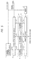
- FIG. 5 shows a block diagram of a configuration of the second embodiment
- Fig. 6 illustrates an operation of the second embodiment.
- the processing of the operation circuit 2b, the erasure locator polynomial operation circuit 2 and the polynomial operation circuits 4a and 5a is carried out by one consolidated operation circuit 2A.
- the processing time of the erasure locator polynomial operation circuit 2 and the polynomial operation circuits 4a and 5a depends on the minimum distance d, and the code length n actually used is sufficiently larger than the minimum distance d.
- the high speed real time decoding may be attained without pipelining the operation circuit 2b, the erasure locator polynomial operation circuit 2 and the polynomial operation circuits 4a and 5a by a separate circuit as it is in the first embodiment.
- the operation of the product polynomial M, the operation of the erasure locator polynomial ⁇ and the processing of the Euclidean algorithm of the polynomial (operation of ⁇ , ⁇ and ⁇ ') can be concurrently carried out.
- a specific configuration of the consolidated operation circuit 2A may use a circuit disclosed in Japanese Patent Application Laid-Open Nos. 63-233613 and 63-233614.
- the circuit scale can be further reduced and the processing of error correction and erasure correction equivalent to that of the first embodiment is attained.
- the present invention may be used as the decoder as well as the encoder or the encoder/decoder.
- b 0 in the generator polynomial although the present invention is not limited thereto but b may be any integer in the generator polynomial.
- the operation of the error evaluator polynomial and the error and erasure locator polynomial uses the Euclidean algorithm although the present invention is not limited thereto but a Burencup Maasay method or a Peterson method may be used.
Abstract
Description
- The present invention relates to an apparatus for correcting an error occurred in a communication path in a digital communication system or a recording medium in a digital recording system, at a receiving or reading station.
- In the digital communication system and the digital recording system, an error correcting code has been used to correct an error occurred in the communication path or the recording medium at the receiving station. As such an error correcting code, Reed-Solomon code (RS code) and BCH code have been well known. Those codes are widely utilized in an optical disk and a satellite communication and encoder and decoder therefor have been implemented in the form of IC.
- Recently, a decoder having a high error correcting capability at a high speed is demanded and various proposals have been made to meet this demand. Before explaining the proposals specifically, assuming that an RS code is used as an error correcting code, a formula expressing a received word R(x) is first explained. The following generator polynomial is used:

where m (a positive integer) represents a bit length of one symbol, n ≦ 2m-1 represents a code length, k=n-(d-1) represents an information length and d represents a minimum distance. - For simplicity, it is assumed that b=0 in the formula (1), the code is defined on a Galois field GF(2m) and a primitive element thereof is at α. The encoding is carried out by the following operation.
- A check polynomial P(x) is generated from the following polynomial I(x) having coefficients represented by an information string {Ik-1, Ik-2, ...., I₀} and the generator polynomial G(x) of the formula (1):


A code word C(x) transmitted is represented by:
where in the formula (4) deg P(x)<n-k represents an order of P(x) and a coefficient of P(x) gives a check digit. - It is assumed that when the code word represented by the formula (4) is transmitted, an error E(x) is added in a communication path and a received word R(x) represented by the following formula (5) is received at a receiving station, wherein the coefficients of E(x) are also represented by the Galois field GF(2m) and are zero if there is no error.

- Various methods have been proposed as a decoding method for the received word R(x) of the RS code, and USP 4,873,688 discloses a decoder having a configuration principle as shown in Fig. 7. In this decoder, a received word Rn-j is inputted to a syndrome
polynomial operation circuit 1, which operates a syndrome polynomial S(x) by the following formula (6).
where
- The syndrome polynomial S(x) is inputted to
polynomial operation circuits polynomial processing circuits 6a - 6c where x is set to αi and the formulas thus processed are inputted to acorrection circuit 7. - In the
correction circuit 7, if the error locator polynomial σ(αi) is 0, it is determined that an error has occurred in an i-th symbol Ri of the received word and the error evaluator ei is calculated by the following formula:
- In Fig. 7, since the processing in the
polynomial operation circuits polynomial processing circuits 6a - 6c can be concurrently carried out, pipeline processing is carried out for the continuously transmitted received words (messages polynomial operation circuit 1 and outputs it in synchronism with the processing of thecorrection circuit 7 to carry out the decoding at a high speed on real time basis. - In this manner, if the error locator polynomial σ(αi) is 0, it is assumed that an error has occurred in the i-th symbol Ri of the received word and a correction value pi = ei is added to the symbol Ri to correct the i-th symbol Ri of the received word.
- In the proposed decoder, 16 errors can be corrected at a rate of 80M bits/sec (bps) on real time basis but it cannot carry out erasure correction.
- On the other hand, the inventor of the present invention have proposed a decoder for carrying out the decoding operation including the erasure correction (USP 5,325,373) and Fig. 10 shows a block diagram of a configuration principle of the proposal.
- In the proposed decode, an erasure locator
polynomial operation circuit 2 and a productpolynomial operation circuit 3 are newly provided, and in the erasure locatorpolynomial operation circuit 2, an erasure location polynomial λ(x) shown by the following formula (9) is calculated:
where Y(i) =αji (i = 1, 2, ..., s) for s erasure locations j₁, j₂, ... js. - In this case, it is assumed that s erasures occur at locations j₁, j₂, ... js in the received word R(x), r errors occurs in addition to the erasure at locations k₁, k₂, ... kr, and the decoder is aware of the erasure locations j₁, j₂, ... js but unaware of the error locations k₁, k₂, ... kr. It is assumed that the erasure is indicated by a flag and a symbol of the erasure location is a dimension on the Galois field GF(2m) as other locations are. It is also assumed that 2t + s + 1 ≦ d (where t represents the number of correctable errors and t ≧ r) is met.
- The syndrome polynomial S(x) calculated by the syndrome
polynmial operation circuit 1 and the erasure locator polynomial λ(x) are inputted to the productpolynomial operation circuit 3 in the same manner as in the decoder of Fig. 7, and in the productpolynomial operation circuit 3, the product polynomial M(x) = S(x)·λ(x) of the syndrome polynomial S(x) and the erasure locator polynomial λ(x) is calcuated. The product polynomial M(x) = S(x)·λ(x) is then inputted to thepolynomial operation circuit 4, and in thepolynomial operation circuits 

where A(x) is a polynomial on the GF(2m). - The error evaluator polynomial ω(x) and the error locator polynomial σ(x) which meet the formulas (10) and (11) are determined by separate processing in the course of the Euclidean algorithm to determine a greatest common divisor polynomial (GCD) of xd-1 and M(x).
- Then, the error evaluator polynomial ω(x), the error locator polynomial σ(x), the differentiation σ'(x) of the error locator polynomial σ(x), the erasure locator polynomial λ(x) and the differentiation λ'(x) of the erasure locator polynomial λ(x) are inputted to the
polynomial processing circuits 6a - 6e and x is set to αi(i = -n + 1, ..., 0) in those formulas. The error evaluator polynomial ω(αi), the error locator polynomial σ(αi), the differentiation σ'(αi) of the error locator polynomial σ(x), the erasure locator polynomial λ(αi) and the differentiation λ'(αi) of the erasure locator polynomial α(x) are inputted to thecorrection circuit 7. - In the
correction circuit 7, if the error locator polynomial σ(αi) is 0, it is determined that an error occurred in the i-th symbol Ri of the received word and the error ei is calculated by the following formula (12) and an erasure value Ei at the erasure location is calculated by the following formula (13):

- In this manner, the correction value pi is added to the i-th symbol Ri of the received word determined to have the error to correct the error and fill the erasure in order to correct the received word where the correction value is represented by:


- In this manner, the decoding operation including the erasure correction can be carried out by the decoder previously proposed by the present inventors.
- The proposed decoder can carry out the-decoding operation including the erasure correction but a circuit scale of the decoder and a processing time increase and the high speed real time processing as disclosed in USP 4,873,688 is difficult to attain.
- It is an object of the present invention to correct the erasure and the error at a high speed.
- In one aspect, hte present invention unifies the processes of calculating the erasure location and value and the error location and value by using a common polynomial to simplify a circuit for the erasure correction and error correction to attain high speed processing.
- According to one embodiment, the present invention provides an apparatus for correcting erasure and error of a received word comprising: syndrome polynomial generation means for generating a syndrome polynomial based on the received word; erasure locator polynomial generation means for generating an erasure locator polynomial based on an erasure location; first product polynomial generation means for generating a first product polynomial which is a product of the syndrome polynomial and the erasure locator polynomial; error evaluator polynomial generation means for generating an error evaluator polynomial based on the first product polynomial; second product polynomial generation means for generating a second product polynomial which is a product of the erasure locator polynomial and the error locator polynomial and a differentiation of the second product polynomial; first numeric operation means for producing the value of differentiation of the second product polynomial with a specific dimension; second operation means for producing a value of the error evaluator polynomial with a specific dimension; third operation means for producing a value of the second product polynomial with a specific dimension; fourth numeric operation means for dividing the operation result of the first numeric operation means by the operation result of the second numeric operation means; determination means for determining whether the operation result of the third numeric operation means is a predetermined value; and correction means for setting the dimension corresponding to the location of the symbols of the received word to the first to third numeric operation means, and when the predetermined value is detected by the determination means, correcting the corresponding symbol by using the operation result of the fourth numeric operation unit.
- Other objectives and advantages besides those discussed above shall be apparent to those skilled in the art from the description of preferred embodiments of the invention which follow. In the description, reference is made to the accompanying drawings, which from a part thereof, and which illustrate examples of the invention. Such examples, however, are not exhaustive of various embodiments of the invention, and therefore reference is made to the claims which follow the description for determining the scope of the invention.
-
- Fig. 1 shows a block diagram of a configuration of an error correction apparatus of a first embodiment,
- Fig. 2 shows a block diagram of a configuration of the error correction apparatus of the first embodiment,
- Fig. 3 show a block diagram of a correction circuit,
- Fig. 4 illustrates an operation of the first embodiment,
- Fig. 5 shows a block diagram of a configuration of the error correction circuit of the first embodiment,
- Fig. 6 illustrates an operation of a second embodiment,
- Fig. 7 shows a block diagram of a configuration of a prior art error correction apparatus,
- Fig. 8 shows a block diagram of a configuration of a prior art error correction apparatus,
- Fig. 9 illustrates an operation of the prior art error correction apparatus,
- Fig. 10 shows a block diagram of a configuration of a prior art erasure correctable error correction apparatus, and
- Figs. 11A and 11B show block diagrams of configurations of a syndrome generator circuit and a polynomial processing circuit.
- Preferred embodiments of this invention will now be described in detail with reference to the accompanying drawings.
- Referring to Figs. 1 to 4, a first embodiment of the present invention is explained. Fig. 1 shows a block diagram of a configuration principle of a decoder of the present embodiment, Fig. 2 shows a block diagram of a configuration of the decoder of the present embodiment, Fig. 3 shows a block diagram of a main portion of a
correction circuit 7 of the present embodiment, and Fig. 4 illustrates an operation of the decoder of the present embodiment. - In the present embodiment, the product
polynomial operation circuit 3 is eliminated from the decoder shown in Fig. 10, and anoperation circuit 2b of the same configuration as that of the erasure locatorpolynomial operation circuit 2 is provided in place of the productpolynomial operation circuit 3. Thepolynomial operation circuits correction circuit 12 operates the error evaluator polynomial ω(x), the error and erasure locator polynomial τ(x) = λ(x)·σ(x) and the differentiation τ'(x) of the error and erasure locator polynomial τ(x), threeerror evaluator polynomials correction circuit 7 of thecorrection circuit 12 has a function to calculate the error- value and the erasure value based on the error evaluator polynomial ω(x), the error and erasure locator polynomial τ(x) = λ(x)·σ(x) and the differentiation τ'(x) of the error and erasure locator polynomial τ(x) to carry out the correction. The configuration of other portions of the present embodiment is identical to that of the decoder of Fig. 10 described above. - In the erasure locator
polynomial operation circuit 2, the processing of λi(x) = λi-1(x) · (1-Yix) with an initial λ(x) being λ₀(x) is repeated for i = 1, ..., s to determine the erasure locator polynomial λs(x). Accordingly, when the initial value for λ(x) is λ₀(x) = S(x), λ(x) = S(x)·λs(x) = M(x) is derived. Accordingly, by proving theoperation circuit 2b of the same configuration as that of the erasure locatorpolynomial operation circuit 2 and changing the initial value from 1 to S(x), the product polynomial M(x) can be calculated. - In the Euclidean algorithm conducted in the
polynomial operation circuits 


- In this case, the error locator polynomial σ(x) = σe (x) and the error evaluator polynomial ω(x) = ωe(x). When the initial value is σ₀(x) = λ(x), the final result polynomial derived from the formulas (15) and (16) is λ(x)·σe(x). Thus, hereinlater, τ(X) = λ(x)·σ(x) is referred to as the error and erasure locator polynomial.
- In the present embodiment the
polynomial processing circuits polynomial processing circuits correction circuit 12, respectively. - The error and erasure locator polynomial τ(x) = λ(x)·σ(x) is λ(αi) = 0 at the erasure location and σ(αi) = 0 at the error location. Thus, τ(αi) = 0 at the error and erasure location so that the erasure location and the error location can be determined.
- The differentiation of the error and erasure locator polynomial τ(x) = λ(x)·σ(x) is represented by the following formula (17):

- At the erasure location, λ(αi) = 0. Thus, from the formula (17), τ'(αi) = λ'(αi)·σ(αi) and the following formula (18) is derived from the formula (13).

- At the error location, σ(αi) = 0. Thus, from the formula (17), τ′(αi) = λ(αi)·σ′(αi) is derived and the following formula (19) is derived from the formula (12).

- In this manner, by using the error and erasure locator polynomial, the error value ei and the erasure value Ei are calculated by the error evaluator polynomial ω(x) and the differentiation of the erasure locator polynomial τ(x). In the present embodiment, the polynomial processing means 6a, 6f and 6g and the
correction circuit 7 form thecorrection circuit 12, and the error value and the erasure value are calculated by the same formula pi = ω(αi)/τ'(αi), and if the error locator polynomial σ(αi) is 0, it is determined that an error occurred at the i-th symbol Ri of the received word and the correction value pi is added to the i-th symbol Ri of the received word to correct the error, and the erasure value Ei is filled at the erasure location to correct the received word. - In the
correction circuit 7 of the present embodiment, as shown in Fig. 3, when an input from a terminal t2 to aswitch 17 is 0 at the error and erasure location, a multiplication circuit 16 (terminal t1) is selected as the output. From the terminal t1, the differentiation τ'(αi) is inputted to areciprocal generator circuit 15 and it is multiplied by ω(αi) by amultiplier circuit 16 to produce a product ω(αi)/τ(αi) to determine the correction value pi. The correction value pi is added to the i-th symbol Ri of the received word by anadder 18. When the input from the terminal 12 is other than 0, theswitch 17 is switched tooutput 0, and the symbol Ri is outputted as it is in theadder 18. - In the present embodiment, the processing of the erasure locator
polynomial operation circuit 2 and theoperation circuit 2b, the processing of thepolynomial operation circuits polynomial processing circuits messages polynomial operation circuit 1 and outputs it in synchronism with the processing of thecorrection circuit 7 to carry out the decoding operation at a high speed on real time basis. - In general, the processing time of the syndrome
polynomial operation circuit 1, thepolynomial processing circuits correction circuit 7 depends on the code length n, and the processing time of the erasure locatorpolynomial operation circuit 2 and thepolynomial operation circuits - Fig. 11A shows a configuration of the syndrome
polynomial operation circuit 1. Amemory element 111 stores a sum of anadder 113. Amultiplier 112 multiplies the content read from thememory element 111 by αi. The adder adds a new received word to the product of themultiplier 112. By setting αk as the multiplier of themultiplier 112, Sk-1 of the formula (7) which is a coefficient of the syndrome polynomial is calculated. In order to attain all coefficients, the circuit of Fig. 11A may be provided for each k. - Fig. 11B shows a configuration of the
polynomial processing circuits memory element 114 and themultiplier 112 multiplies A₁ read from thememory element 111 by α. Same is true for other Aj. Thememory element 116outputs 1. The output of theadder 117 after i shifts is A(αi). When thepolynomial processing circuit 6g determines τ(αi)-1 = -1 in place of τ(αi) = 0, thememory element 116 is not necessary. - Specific configurations of the erasure locator
polynomial operation circuit 2, theoperation circuit 2b and thepolynomial operation circuits - In accordance with the present embodiment, the operation is conducted by the
operation circuit 2b of the same configuration as that of the erasure locatorpolynomial operation circuit 2 with the initial value of the erasure locator polynomial λ(x) being the syndrome polynomial S(x), the circuit scale can be reduced and the processing speed can be increased in thepolynomial operation circuits polynomial operation circuits correction circuit 12 operates the error locator polynomial ω(x), the error and erasure locator polynomial τ(x) = λ(x)·σ(x) and the differentiation τ'(x) of the error and erasure locator polynomial τ(x) so that the processing of the threepolynomial processing circuits - Referring to Figs. 5 and 6, a second embodiment of the present invention is explained. Fig. 5 shows a block diagram of a configuration of the second embodiment and Fig. 6 illustrates an operation of the second embodiment.
- In the present embodiment, as shown in Fig. 5, the processing of the
operation circuit 2b, the erasure locatorpolynomial operation circuit 2 and thepolynomial operation circuits consolidated operation circuit 2A. As described above, the processing time of the erasure locatorpolynomial operation circuit 2 and thepolynomial operation circuits operation circuit 2b, the erasure locatorpolynomial operation circuit 2 and thepolynomial operation circuits - A specific configuration of the
consolidated operation circuit 2A may use a circuit disclosed in Japanese Patent Application Laid-Open Nos. 63-233613 and 63-233614. - In accordance with the present embodiment, the circuit scale can be further reduced and the processing of error correction and erasure correction equivalent to that of the first embodiment is attained.
- In the first embodiment, the polynomial processing circuits are reduced to the three
circuits polynomial operation circuit 3 by theoperation circuit 2b, (2) replacing thepolynomial operation circuit 5 for calculating σ(x) and σ'(x) by thepolynomial operation circuit 5a for calculating τ(x)(= σ(x)·λ(x)) and τ'(x), and (3) determining the error and erasure location by τ(αi) = 0 and the error value ei and the erasure value Ei by ω(αi)/τ'(αi) although the present invention is not limited thereto and one or two of the processes (1), (2) and (3) may be carried out. When the process (2) is not carried out, σ(x) may be determined in the conventional manner and it may be multiplied by λ(x) to produce τ(x) (= α(x)·λ(x)). - In the decoder which carries out the erasure correction, it has been known to use the erasure location as the location of the check symbol (parity bit). Thus, the present invention may be used as the decoder as well as the encoder or the encoder/decoder. In the preferred embodiments, b = 0 in the generator polynomial although the present invention is not limited thereto but b may be any integer in the generator polynomial. In the preferred embodiments, the operation of the error evaluator polynomial and the error and erasure locator polynomial uses the Euclidean algorithm although the present invention is not limited thereto but a Burencup Maasay method or a Peterson method may be used.
- Although the present invention has been described in its preferred form with a certain degree of particularity, many apparently widely different embodiments of the invention may be made without departing from the spirit and scope thereof. It is to be understood that the invention is not limited to the specific embodiments thereof except as defined in the appended claims.
Claims (11)
- An apparatus for correcting erasure and error of a received word comprising:
syndrome polynomial generation means for generating a syndrome polynomial based on the received word;
erasure locator polynomial generation means for generating an erasure locator polynomial based on an erasure location;
first product polynomial generation means for generating a first product polynomial which is a product of the syndrome polynomial and the erasure locator polynomial;
error evaluator polynomial generation means for generating an error evaluator polynomial based on the first product polynomial;
second product polynomial generation means for generating a second product polynomial which is a product of the erasure locator polynomial and the error locator polynomial and a differentiation of the second product polynomial;
first numeric operation means for producing the value of differentiation of the second product polynomial with a specific dimension;
second operation means for producing a value of the error evaluator polynomial with a specific dimension;
third operation means for producing a value of the second product polynomial with a specific dimension;
fourth numeric operation means for dividing the operation result of said first numeric operation means by the operation result of said second numeric operation means;
determination means for determining whether the operation result of said third numeric operation means is a predetermined value; and
correction means for setting the dimension corresponding to the location of the symbols of the received word to said first to third numeric operation means, and when the predetermined value is detected by said determination means, correcting the corresponding symbol by using the operation result of said fourth numeric operation unit. - An apparatus according to Claim 1 wherein the dimensions corresponding to the location of the symbols of the received word are sequentially set to said first to third numeric operation means, and the symbols of the received word are sequentially inputted to said correction means and said correction means corrects the symbols or sequentially output as they are.
- An apparatus according to Claim 2 further comprising memory means for storing the received word in parallel to said syndrome polynomial generation means, said received word being read out by said correction means.
- An apparatus according to Claim 1 wherein said first product polynomial generation means generates an erasure locator polynomial having the syndrome polynomial generated by said syndrome polynomial generation means as an initial value, as the first polynomial based on the erasure location.
- An apparatus according to Claim 4 wherein said erasure locator polynomial generation means and said first product polynomial generation means generates erasure locator polynomials with different initial values by a common operation circuit.
- An apparatus according to Claim 1 wherein said second product generation means operates the error locator polynomial having the erasure locator polynomial generated by said erasure locator polynomial generation means as an initial value, as the second product polynomial by a Euclidean algolithm.
- An apparatus according to Claim 1 wherein at least two of said erasure locator polynomial generation means, said first product polynomial generation means, said error evaluator polynomial generation means and said first product polynomial generation means use a common operation circuit.
- An apparatus according to Claim 1 wherein said predetermined value is zero.
- An error correction apparatus comprising means for calculating erasure locations and error locations using a common polynomial.
- An apparatus having the features of any combination of the preceding claims.
- A reproducing apparatus for recorded or broadcast information, including error correction apparatus as claimed in any preceding claim.
Applications Claiming Priority (3)
| Application Number | Priority Date | Filing Date | Title |
|---|---|---|---|
| JP348569/93 | 1993-12-27 | ||
| JP34856993 | 1993-12-27 | ||
| JP34856993A JP3255386B2 (en) | 1993-12-27 | 1993-12-27 | Error correction code decoder |
Publications (3)
| Publication Number | Publication Date |
|---|---|
| EP0660535A2 true EP0660535A2 (en) | 1995-06-28 |
| EP0660535A3 EP0660535A3 (en) | 1995-12-13 |
| EP0660535B1 EP0660535B1 (en) | 2002-09-11 |
Family
ID=18397904
Family Applications (1)
| Application Number | Title | Priority Date | Filing Date |
|---|---|---|---|
| EP94309745A Expired - Lifetime EP0660535B1 (en) | 1993-12-27 | 1994-12-23 | Apparatus for uniformly correcting erasure and error of received word by using a common polynomial |
Country Status (4)
| Country | Link |
|---|---|
| US (1) | US5541937A (en) |
| EP (1) | EP0660535B1 (en) |
| JP (1) | JP3255386B2 (en) |
| DE (1) | DE69431339D1 (en) |
Cited By (2)
| Publication number | Priority date | Publication date | Assignee | Title |
|---|---|---|---|---|
| WO1996024195A1 (en) * | 1995-01-31 | 1996-08-08 | Philips Electronics N.V. | A polynomial divider which can perform euclid's algorithm to produce an error locator polynomial from an error syndrome polynomial, and apparatus including the polynomial divider |
| EP1468499A1 (en) * | 2002-01-23 | 2004-10-20 | Thomson Licensing | Intra-decoder component block messaging |
Families Citing this family (10)
| Publication number | Priority date | Publication date | Assignee | Title |
|---|---|---|---|---|
| JPH0936755A (en) * | 1995-07-21 | 1997-02-07 | Canon Inc | Decoder and its method |
| US6347389B1 (en) * | 1999-03-23 | 2002-02-12 | Storage Technology Corporation | Pipelined high speed reed-solomon error/erasure decoder |
| TW441195B (en) * | 1999-07-16 | 2001-06-16 | Via Tech Inc | Signal decoding method |
| US20080282128A1 (en) * | 1999-08-04 | 2008-11-13 | Super Talent Electronics, Inc. | Method of Error Correction Code on Solid State Disk to Gain Data Security and Higher Performance |
| US20050068874A1 (en) * | 2002-01-22 | 2005-03-31 | Jacobus Petrus Josephus Heemskerk | Record carrier |
| US6712798B2 (en) * | 2002-03-18 | 2004-03-30 | Corazon Technologies, Inc. | Multilumen catheters and methods for their use |
| JP3843952B2 (en) * | 2003-02-27 | 2006-11-08 | ソニー株式会社 | Decoding device, error locator polynomial calculation method, program |
| US8832523B2 (en) * | 2006-03-03 | 2014-09-09 | Ternarylogic Llc | Multi-state symbol error correction in matrix based codes |
| US7539927B2 (en) * | 2005-04-14 | 2009-05-26 | Industrial Technology Research Institute | High speed hardware implementation of modified Reed-Solomon decoder |
| US9203436B2 (en) * | 2006-07-12 | 2015-12-01 | Ternarylogic Llc | Error correction in multi-valued (p,k) codes |
Citations (6)
| Publication number | Priority date | Publication date | Assignee | Title |
|---|---|---|---|---|
| US4162480A (en) * | 1977-01-28 | 1979-07-24 | Cyclotomics, Inc. | Galois field computer |
| EP0167627A1 (en) * | 1983-12-20 | 1986-01-15 | Sony Corporation | Method and apparatus for decoding error correction code |
| EP0278383A2 (en) * | 1987-02-06 | 1988-08-17 | Sony Corporation | Error correction method using reed-solomon code |
| EP0296828A2 (en) * | 1987-06-22 | 1988-12-28 | Sony Corporation | Method and apparatus for decoding reed-solomon code |
| US4868828A (en) * | 1987-10-05 | 1989-09-19 | California Institute Of Technology | Architecture for time or transform domain decoding of reed-solomon codes |
| FR2673341A1 (en) * | 1991-02-25 | 1992-08-28 | Broadcast Television Syst | CIRCUIT ARRANGEMENT FOR DETECTING AND CORRECTING DEFECTS IN DATA WORDS. |
Family Cites Families (7)
| Publication number | Priority date | Publication date | Assignee | Title |
|---|---|---|---|---|
| US4649541A (en) * | 1984-11-21 | 1987-03-10 | The United States Of America As Represented By The Administrator Of The National Aeronautics And Space Administration | Reed-Solomon decoder |
| US4747103A (en) * | 1985-03-21 | 1988-05-24 | Canon Kabushiki Kaisha | Signal processing apparatus for correcting decoding errors |
| JPH0728227B2 (en) * | 1985-06-07 | 1995-03-29 | ソニー株式会社 | Decoding device for BCH code |
| US5325373A (en) * | 1986-12-22 | 1994-06-28 | Canon Kabushiki Kaisha | Apparatus for encoding and decoding reed-solomon code |
| JP2603244B2 (en) * | 1987-03-20 | 1997-04-23 | キヤノン株式会社 | Error correction device |
| JP2603243B2 (en) * | 1987-03-20 | 1997-04-23 | キヤノン株式会社 | Error correction device |
| US4873688A (en) * | 1987-10-05 | 1989-10-10 | Idaho Research Foundation | High-speed real-time Reed-Solomon decoder |
-
1993
- 1993-12-27 JP JP34856993A patent/JP3255386B2/en not_active Expired - Fee Related
-
1994
- 1994-12-23 EP EP94309745A patent/EP0660535B1/en not_active Expired - Lifetime
- 1994-12-23 US US08/362,989 patent/US5541937A/en not_active Expired - Lifetime
- 1994-12-23 DE DE69431339T patent/DE69431339D1/en not_active Expired - Lifetime
Patent Citations (6)
| Publication number | Priority date | Publication date | Assignee | Title |
|---|---|---|---|---|
| US4162480A (en) * | 1977-01-28 | 1979-07-24 | Cyclotomics, Inc. | Galois field computer |
| EP0167627A1 (en) * | 1983-12-20 | 1986-01-15 | Sony Corporation | Method and apparatus for decoding error correction code |
| EP0278383A2 (en) * | 1987-02-06 | 1988-08-17 | Sony Corporation | Error correction method using reed-solomon code |
| EP0296828A2 (en) * | 1987-06-22 | 1988-12-28 | Sony Corporation | Method and apparatus for decoding reed-solomon code |
| US4868828A (en) * | 1987-10-05 | 1989-09-19 | California Institute Of Technology | Architecture for time or transform domain decoding of reed-solomon codes |
| FR2673341A1 (en) * | 1991-02-25 | 1992-08-28 | Broadcast Television Syst | CIRCUIT ARRANGEMENT FOR DETECTING AND CORRECTING DEFECTS IN DATA WORDS. |
Cited By (4)
| Publication number | Priority date | Publication date | Assignee | Title |
|---|---|---|---|---|
| WO1996024195A1 (en) * | 1995-01-31 | 1996-08-08 | Philips Electronics N.V. | A polynomial divider which can perform euclid's algorithm to produce an error locator polynomial from an error syndrome polynomial, and apparatus including the polynomial divider |
| EP1468499A1 (en) * | 2002-01-23 | 2004-10-20 | Thomson Licensing | Intra-decoder component block messaging |
| EP1468499A4 (en) * | 2002-01-23 | 2005-12-14 | Thomson Licensing | Intra-decoder component block messaging |
| US7020826B2 (en) | 2002-01-23 | 2006-03-28 | Thomson Licensing | Intra-decoder component block messaging |
Also Published As
| Publication number | Publication date |
|---|---|
| EP0660535A3 (en) | 1995-12-13 |
| DE69431339D1 (en) | 2002-10-17 |
| EP0660535B1 (en) | 2002-09-11 |
| US5541937A (en) | 1996-07-30 |
| JP3255386B2 (en) | 2002-02-12 |
| JPH07202718A (en) | 1995-08-04 |
Similar Documents
| Publication | Publication Date | Title |
|---|---|---|
| US4694455A (en) | Decoding method for multiple bit error correction BCH codes | |
| US6347389B1 (en) | Pipelined high speed reed-solomon error/erasure decoder | |
| US5099482A (en) | Apparatus for detecting uncorrectable error patterns when using Euclid's algorithm to decode Reed-Solomon (BCH) codes | |
| US4504948A (en) | Syndrome processing unit for multibyte error correcting systems | |
| US6119262A (en) | Method and apparatus for solving key equation polynomials in decoding error correction codes | |
| US6543026B1 (en) | Forward error correction apparatus and methods | |
| JP3176171B2 (en) | Error correction method and apparatus | |
| US5541937A (en) | Apparatus for uniformly correcting erasure and error of received word by using a common polynomial | |
| JPH0653842A (en) | Method and circuit for decoding of rs code data signal | |
| US8201061B2 (en) | Decoding error correction codes using a modular single recursion implementation | |
| EP0753942A2 (en) | Word-wise processing for reed-solomon codes | |
| US6651214B1 (en) | Bi-directional decodable Reed-Solomon codes | |
| US7047481B2 (en) | Decoding method and decoder for Reed Solomon code | |
| US6915478B2 (en) | Method and apparatus for computing Reed-Solomon error magnitudes | |
| US20030126543A1 (en) | Method and apparatus for solving key equation polynomials in decoding error correction codes | |
| US6421807B1 (en) | Decoding apparatus, processing apparatus and methods therefor | |
| US8181096B2 (en) | Configurable Reed-Solomon decoder based on modified Forney syndromes | |
| US6446233B1 (en) | Forward error correction apparatus and methods | |
| US5978950A (en) | Polynomial evaluator for use in a reed-solomon decoder | |
| JPH1117557A (en) | Error correction method and device therefor | |
| EP0793352A2 (en) | Apparatus for determining the error evaluator polynomial for use in a Reed-Solomon decoder | |
| JP3583905B2 (en) | Error correction device | |
| KR950008485B1 (en) | Unierror correction r-s decoder | |
| JP2611204B2 (en) | Error correction method | |
| JP2553571B2 (en) | Galois field arithmetic unit |
Legal Events
| Date | Code | Title | Description |
|---|---|---|---|
| PUAI | Public reference made under article 153(3) epc to a published international application that has entered the european phase |
Free format text: ORIGINAL CODE: 0009012 |
|
| AK | Designated contracting states |
Kind code of ref document: A2 Designated state(s): DE FR GB |
|
| PUAL | Search report despatched |
Free format text: ORIGINAL CODE: 0009013 |
|
| AK | Designated contracting states |
Kind code of ref document: A3 Designated state(s): DE FR GB |
|
| 17P | Request for examination filed |
Effective date: 19960424 |
|
| 17Q | First examination report despatched |
Effective date: 19990728 |
|
| GRAG | Despatch of communication of intention to grant |
Free format text: ORIGINAL CODE: EPIDOS AGRA |
|
| GRAG | Despatch of communication of intention to grant |
Free format text: ORIGINAL CODE: EPIDOS AGRA |
|
| GRAG | Despatch of communication of intention to grant |
Free format text: ORIGINAL CODE: EPIDOS AGRA |
|
| GRAH | Despatch of communication of intention to grant a patent |
Free format text: ORIGINAL CODE: EPIDOS IGRA |
|
| GRAH | Despatch of communication of intention to grant a patent |
Free format text: ORIGINAL CODE: EPIDOS IGRA |
|
| GRAA | (expected) grant |
Free format text: ORIGINAL CODE: 0009210 |
|
| AK | Designated contracting states |
Kind code of ref document: B1 Designated state(s): DE FR GB |
|
| PG25 | Lapsed in a contracting state [announced via postgrant information from national office to epo] |
Ref country code: FR Free format text: LAPSE BECAUSE OF FAILURE TO SUBMIT A TRANSLATION OF THE DESCRIPTION OR TO PAY THE FEE WITHIN THE PRESCRIBED TIME-LIMIT Effective date: 20020911 |
|
| REG | Reference to a national code |
Ref country code: GB Ref legal event code: FG4D |
|
| REF | Corresponds to: |
Ref document number: 69431339 Country of ref document: DE Date of ref document: 20021017 |
|
| PGFP | Annual fee paid to national office [announced via postgrant information from national office to epo] |
Ref country code: GB Payment date: 20021209 Year of fee payment: 9 |
|
| PG25 | Lapsed in a contracting state [announced via postgrant information from national office to epo] |
Ref country code: DE Free format text: LAPSE BECAUSE OF FAILURE TO SUBMIT A TRANSLATION OF THE DESCRIPTION OR TO PAY THE FEE WITHIN THE PRESCRIBED TIME-LIMIT Effective date: 20021212 |
|
| EN | Fr: translation not filed | ||
| PLBE | No opposition filed within time limit |
Free format text: ORIGINAL CODE: 0009261 |
|
| STAA | Information on the status of an ep patent application or granted ep patent |
Free format text: STATUS: NO OPPOSITION FILED WITHIN TIME LIMIT |
|
| 26N | No opposition filed |
Effective date: 20030612 |
|
| PG25 | Lapsed in a contracting state [announced via postgrant information from national office to epo] |
Ref country code: GB Free format text: LAPSE BECAUSE OF NON-PAYMENT OF DUE FEES Effective date: 20031223 |
|
| GBPC | Gb: european patent ceased through non-payment of renewal fee |
Effective date: 20031223 |