EP0660389A2 - Method of manufacturing semiconductor devices having element separating regions - Google Patents
Method of manufacturing semiconductor devices having element separating regions Download PDFInfo
- Publication number
- EP0660389A2 EP0660389A2 EP94120685A EP94120685A EP0660389A2 EP 0660389 A2 EP0660389 A2 EP 0660389A2 EP 94120685 A EP94120685 A EP 94120685A EP 94120685 A EP94120685 A EP 94120685A EP 0660389 A2 EP0660389 A2 EP 0660389A2
- Authority
- EP
- European Patent Office
- Prior art keywords
- material layer
- film
- substrate
- layer
- element separating
- Prior art date
- Legal status (The legal status is an assumption and is not a legal conclusion. Google has not performed a legal analysis and makes no representation as to the accuracy of the status listed.)
- Granted
Links
Images


Classifications
-
- H—ELECTRICITY
- H01—ELECTRIC ELEMENTS
- H01L—SEMICONDUCTOR DEVICES NOT COVERED BY CLASS H10
- H01L21/00—Processes or apparatus adapted for the manufacture or treatment of semiconductor or solid state devices or of parts thereof
- H01L21/02—Manufacture or treatment of semiconductor devices or of parts thereof
- H01L21/04—Manufacture or treatment of semiconductor devices or of parts thereof the devices having at least one potential-jump barrier or surface barrier, e.g. PN junction, depletion layer or carrier concentration layer
- H01L21/18—Manufacture or treatment of semiconductor devices or of parts thereof the devices having at least one potential-jump barrier or surface barrier, e.g. PN junction, depletion layer or carrier concentration layer the devices having semiconductor bodies comprising elements of Group IV of the Periodic System or AIIIBV compounds with or without impurities, e.g. doping materials
- H01L21/30—Treatment of semiconductor bodies using processes or apparatus not provided for in groups H01L21/20 - H01L21/26
- H01L21/302—Treatment of semiconductor bodies using processes or apparatus not provided for in groups H01L21/20 - H01L21/26 to change their surface-physical characteristics or shape, e.g. etching, polishing, cutting
- H01L21/306—Chemical or electrical treatment, e.g. electrolytic etching
- H01L21/308—Chemical or electrical treatment, e.g. electrolytic etching using masks
- H01L21/3081—Chemical or electrical treatment, e.g. electrolytic etching using masks characterised by their composition, e.g. multilayer masks, materials
-
- H—ELECTRICITY
- H01—ELECTRIC ELEMENTS
- H01L—SEMICONDUCTOR DEVICES NOT COVERED BY CLASS H10
- H01L21/00—Processes or apparatus adapted for the manufacture or treatment of semiconductor or solid state devices or of parts thereof
- H01L21/70—Manufacture or treatment of devices consisting of a plurality of solid state components formed in or on a common substrate or of parts thereof; Manufacture of integrated circuit devices or of parts thereof
- H01L21/71—Manufacture of specific parts of devices defined in group H01L21/70
- H01L21/76—Making of isolation regions between components
- H01L21/762—Dielectric regions, e.g. EPIC dielectric isolation, LOCOS; Trench refilling techniques, SOI technology, use of channel stoppers
- H01L21/76224—Dielectric regions, e.g. EPIC dielectric isolation, LOCOS; Trench refilling techniques, SOI technology, use of channel stoppers using trench refilling with dielectric materials
Definitions
- the present invention relates to a method of manufacturing semiconductor devices, and more specifically to a method of manufacturing semiconductor devices having buried element separating regions.
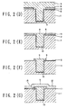
- Figs. 3(A) to 3(D) are cross-sectional views for assistance in explaining the conventional method of manufacturing the buried element separating region, in particular.
- a SiO2 film 2 with a thickness of about 10 nm, for instance is formed on a Si substrate by thermal oxidization.
- a resist film 5 is applied onto the SiO2 film 2, and further the resist film 5 is formed into a predetermined shape in accordance with photolithography. Further, by using the formed resist film 5 as a mask, an element separating trench 7 with a depth of about 500 nm, for instance is formed in the SiO2 film 2 and the Si substrate by anisotropic etching.
- another SiO2 film 8 with a thickness of a bout 20 nm, for instance is deposited thereon by thermal oxidization.
- another SiO2 9 film with a thickness of about 1 ⁇ m, for instance is further deposited thereon as a trench filling substance.
- the deposited filling substance of the SiO2 film 9 is etched back by anisotropic etching or polishing to complete the buried element separating region 10.
- a gate oxide film 11 with a thickness of about 10 nm is formed thereon by thermal oxidization.
- a poly crystalline Si film 12 with a thickness of about 300 nm, for instance is formed into a predetermined shape as a gate electrode.
- kink characteristics occur because the characteristics of a parasitic transistor are added to the original I-V characteristics of the MOSFET.
- edge portion 13 is a corner of the Si substrate as shown in Fig. 3(D)
- a mechanical stress tends to be concentrated and thereby a defect tends to occurs easily at the edge portion 13, thus causing a problem in that a leakage tends to occur in the gate oxide film 11.
- the present invention provides a method of manufacturing a semiconductor device, comprising the steps of: forming a first material layer (3) and a second material layer (5) in sequence on a surface of a semiconductor substrate (1); forming a first opening on the first material layer (3) and a second opening in the second material layer (5), the first opening being larger than the second opening; forming an element separating trench (7) under the second opening in the substrate (1) by using the second material layer (5) as a mask; removing the second material layer (5); depositing a filling material (9) on the element separating trench (7), the substrate (1) and the first material layer (3); and etching back the filling material (9) by using the first material layer (3) as a stopper.
- the present invention provides a method of manufacturing a semiconductor device, comprising the steps of: forming a first material layer (3), a second material layer (4), and a third material layer (5) on a surface of a semiconductor substrate (1); patterning the third material layer (5); etching the second and the first material layers (4, 3) by using the third material layer (5) as a mask to form a first opening on the first material layer (3) and a second opening in the second material layer (4), the first opening being larger than the second opening; forming an element separating trench (7) under the second opening in the substrate (1) by using the second material layer (4) as a mask; removing the second material layer (4); depositing a filling material (9) on the element separating trench (7), the substrate (1) and the first material layer (3); and etching back the filling material (9) by using the first material layer (3) as a stopper.
- the first opening of the first layer deposited on the semiconductor substrate is determined to be broader than the opening of the element separating trench formed on the semiconductor substrate, it is possible to cover the edge portion (formed between the substrate surface and the element separating trench) with a filling substance deposited in the trench and on the surface of the semiconductor substrate. As a result, it is possible to eliminate defects which may cause the electric field concentration and the gate oxide film leakage at the edge portion.
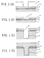
- Fig. 1(A) to (G) show a first embodiment of the manufacturing method according to the present invention.
- a SiO2 film 2 with a thickness of about 10 nm, for instance is formed on a Si substrate 1 by thermal oxidization. Then, a poly crystalline Si film 3 with a thickness of about 200 nm, for instance is deposited by chemical vapor deposition method. Further, a SiO2 film 4 with a thickness of about 200 nm, for instance is deposited thereon by chemical vapor deposition method. After that, a resist film 5 is applied onto the SiO2 film 4, and then the resist film 5 is formed into a predetermined shape in accordance with photolithography.
- the SiO2 film 4 and the poly crystalline Si film 3 are both process by anisotropic etching in sequence to remove the resist film 5.
- the poly crystalline Si film 3 is etched back by isotropic etching to form a recessed portion 6 with a recession of about 100 nm, for instance.
- CDE method chemical dry etching
- wet processing, etc. are known. In any method, however, it is possible to form the recessed portion 6 as shown in Fig. 1(B).
- the SiO2 film 2 is removed, and further the Si substrate 1 is etched to form an element separating trench 7 with a depth of about 500 nm (so that a buried element separating region can be formed later).
- the SiO2 film 4 used as a mask for etching the Si substrate 1 is also etched simultaneously, since the film thickness (10 nm) of the SiO2 film 2 is sufficiently thinner than that (200 nm) of the SiO2 film 4 (used as an etching mask), the thickness of the SiO2 film 4 can be almost maintained.
- a SiO2 film 8 with a thickness of about 20 nm is formed by thermal oxidization in order to remove defects produced on the Si substrate 1 when the Si substrate 1 is etched.
- SiO2 film 9 with a thickness of about 1 ⁇ m, for instance is further deposited thereon by chemical vapor deposition method as a filling substance of the element separating trench 7 (as a buried element separation).
- the deposited filling substance of SiO2 film 9 is etched back by anisotropic etching or polishing by use of the poly crystalline Si film 3 as a stopper film, the etching of the filling substance SiO2 film 9 can be stopped at a level flush with the poly crystalline Si film 3 to form the buried element separating region 10.
- the poly crystalline Si film 3 used as a stopper during the etching back is removed to complete the buried element separating region 10.
- a poly crystalline Si film 12 is deposited all over the device to complete a semiconductor device.
- the buried element separating region 10 formed in accordance with the above-mentioned method is of concave shape.
- the edge portion 13 of the Si substrate 1 is covered with the SiO2 film 9 for filling the buried element separating trench 7, it is possible to eliminate electric field concentration and defects at the corner thereof, so that it is possible to realize an LSI of high reliability.
- the SiO2 film 4 is used as a mask for etching the Si substrate 1 to form the element separating trench 7, and the poly crystalline Si film 3 is used as an etching stopper film when the filling substance of the buried element separating region 10 is etched back.
- the etching mask used when the Si substrate 1 is etched to form the element separating trench 7
- the etching stopper used when the filling substance is etched back
- a WSi film, TiN film, carbon film, SiN film, etc are usable as the etching stopper.
- the SiO2 is used as the substance for filling the buried element separating trench 7.
- other filling substances such as Si, SiN, etc.
- SiO2 film and SiN film can be used as the poly crystalline Si film 3 and the SiO2 film 4, both shown in Fig. 1(A), or vice versa.
- the poly crystalline Si film 3 and the SiO2 film 4 are deposited in sequence; these films 3 and 4 are etched by use of a resist film 5 formed into a predetermined shape as a mask; and the SiO2 film 4 is used as a mask to etch the element separating trench 7.
- a resist film 5 formed into a predetermined shape as a mask
- the SiO2 film 4 is used as a mask to etch the element separating trench 7.
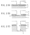
- Fig. 2(A) to (C) show a second embodiment of the manufacturing method according to the present invention, which is described from the above-mentioned point of view..
- a SiO2 film 2 with a thickness of about 10 nm, for instance is formed on a Si substrate 1 by thermal oxidization.
- a poly crystalline Si film 3 with a thickness of about 200 nm, for instance is deposited by chemical vapor deposition method.
- a resist film 5 is applied thereonto and formed into a predetermined shape in accordance with photolithography.
- the poly crystalline Si film 3 is processed by anisotropic etching, and further etched by isotropic etching to form a recessed portion 6 with a recess of about 100 nm.
- CDE method chemical dry etching
- wet processing etc.
- the SiO2 film 2 is removed to expose the surface of the Si substrate 1, and the exposed Si substrate 1 is etched to a depth of about 500 nm (sufficient depth as the buried element separation) by use of the SiO2 film 2 as a mask to form an element separating trench 7.
- ions are implanted to control the threshold level to a predetermined value; after the SiO2 film 2 and the SiO2 film 8 above the surface of the Si substrate 1 has been removed, a gate oxide film 11 with a thickness of about 10 nm is formed by thermal oxidization; and after that, a poly crystalline Si film 12 with a thickness of about 300 nm, for instance is deposited and formed into a predetermined shape as a gate electrode.
- Fig. 1(G) the device thus obtained is shown in Fig. 1(G).
- Si nitride film instead of the SiO2 films 2, 4 and 8. Further, it is also possible to use both the SiO2 film and Si nitride film in combination.
- the SiO2 film 2 can be replaced with a carbon film, TiN film, or siliside metal, etc.
- the SiO2 film 4 can be replaced with Si oxide film, Si nitride film, Si film, or resist film, etc.
- the SiO2 film 8 can be replaced with Si oxide film, Si nitride film, or Si film.
- the semiconductor device As described above, in the method of manufacturing the semiconductor device according to the present invention, after materials are deposited in sequence on the substrate, a part of the material is recessed in the horizontal direction along the surface of the substrate to form a recessed portion; after that, an element separating trench is formed; another material is deposited; and the whole device is etched back. Therefore, since a convex buried element separating region 10 can be formed and in addition since the edge portion of the substrate can be covered with the element separating region filling material, it is possible to prevent the electric field from being concentrated at the corner portion of the substrate and to prevent a defect from occurring at the corner portion of the substrate, thus providing miniaturized semiconductor device of higher reliability.
- the edge portion of the element separating trench formed in the semiconductor substrate can be covered with the trench filling material, it is possible to provide a semiconductor device which can suppress electric field concentration at the edge portion of the substrate and thereby to prevent the defect from being produced at the edge portion thereof.
Abstract

Description
- The present invention relates to a method of manufacturing semiconductor devices, and more specifically to a method of manufacturing semiconductor devices having buried element separating regions.
- Recently, with the advance of the microminiaturization of the semiconductor integrated circuit devices, the distance between element separating regions has become narrower and narrower for each generation. To cope with the narrower element separating regions, the buried element separation has been developed.
- Figs. 3(A) to 3(D) are cross-sectional views for assistance in explaining the conventional method of manufacturing the buried element separating region, in particular.
- First, as shown in Fig. 3(A), a
SiO₂ film 2 with a thickness of about 10 nm, for instance is formed on a Si substrate by thermal oxidization. - Then, a
resist film 5 is applied onto theSiO₂ film 2, and further theresist film 5 is formed into a predetermined shape in accordance with photolithography. Further, by using the formedresist film 5 as a mask, anelement separating trench 7 with a depth of about 500 nm, for instance is formed in theSiO₂ film 2 and the Si substrate by anisotropic etching. - Successively, as shown in Fig. 3(B), to eliminate damage caused by etching, another
SiO₂ film 8 with a thickness of a bout 20 nm, for instance is deposited thereon by thermal oxidization. After that, anotherSiO₂ 9 film with a thickness of about 1 µm, for instance is further deposited thereon as a trench filling substance. - Further, as shown in Fig. 3(C), the deposited filling substance of the
SiO₂ film 9 is etched back by anisotropic etching or polishing to complete the buriedelement separating region 10. - Further, as shown in Fig. 3(D), after the ion implantation process to control the threshold value of a MOSFET, a
gate oxide film 11 with a thickness of about 10 nm is formed thereon by thermal oxidization. Further, a polycrystalline Si film 12 with a thickness of about 300 nm, for instance is formed into a predetermined shape as a gate electrode. - In the above-mentioned conventional method of manufacturing the buried
element separating region 10, since a process margin must be taken into account in the etching back process shown in Fig. 3(C), a predetermined over-etching is inevitably required in Fig. 3(C), with the result that the surface of the buriedelement separating region 10 is formed being slightly recessed from the surface of theSi substrate 1. Therefore, as shown in Fig. 3(D), anedge portion 13 remains at the buriedelement separating region 10, so that thegate oxide film 11 formed thereon is also formed with anedge portion 13. - As described above, in the conventional method of manufacturing the semiconductor device, since a stepped portion is generated at the
edge portion 13 of the buriedelement separating region 10 and thereby also at the edge portion of thegate oxide film 11 in the same way, an electric field is inevitably concentrated at thisedge portion 13 of the buriedelement separating region 10. - Once the electric field concentration occurs as described above, the characteristics between gate voltage and drain current deteriorate, as shown by a solid line curve in Fig. 4, which is referred to as kink characteristics in comparison with the normal characteristics as shown by dashed lines. The kink characteristics occur because the characteristics of a parasitic transistor are added to the original I-V characteristics of the MOSFET.
- On the other hand, since the
edge portion 13 is a corner of the Si substrate as shown in Fig. 3(D), a mechanical stress tends to be concentrated and thereby a defect tends to occurs easily at theedge portion 13, thus causing a problem in that a leakage tends to occur in thegate oxide film 11. - Accordingly, it is the object of the present invention to provide a method of manufacturing semiconductor devices, which can realize buried element separations suitable for microminiaturized integrated circuits, without forming defects which may cause electric field concentration and gate oxide film leakage.
- To achieve the above-mentioned object, the present invention (Fig. 3) provides a method of manufacturing a semiconductor device, comprising the steps of: forming a first material layer (3) and a second material layer (5) in sequence on a surface of a semiconductor substrate (1); forming a first opening on the first material layer (3) and a second opening in the second material layer (5), the first opening being larger than the second opening; forming an element separating trench (7) under the second opening in the substrate (1) by using the second material layer (5) as a mask; removing the second material layer (5); depositing a filling material (9) on the element separating trench (7), the substrate (1) and the first material layer (3); and etching back the filling material (9) by using the first material layer (3) as a stopper.
- Further, the present invention (Fig. 1) provides a method of manufacturing a semiconductor device, comprising the steps of: forming a first material layer (3), a second material layer (4), and a third material layer (5) on a surface of a semiconductor substrate (1); patterning the third material layer (5); etching the second and the first material layers (4, 3) by using the third material layer (5) as a mask to form a first opening on the first material layer (3) and a second opening in the second material layer (4), the first opening being larger than the second opening; forming an element separating trench (7) under the second opening in the substrate (1) by using the second material layer (4) as a mask; removing the second material layer (4); depositing a filling material (9) on the element separating trench (7), the substrate (1) and the first material layer (3); and etching back the filling material (9) by using the first material layer (3) as a stopper.
- In the manufacturing method according to the present invention, since the first opening of the first layer deposited on the semiconductor substrate is determined to be broader than the opening of the element separating trench formed on the semiconductor substrate, it is possible to cover the edge portion (formed between the substrate surface and the element separating trench) with a filling substance deposited in the trench and on the surface of the semiconductor substrate. As a result, it is possible to eliminate defects which may cause the electric field concentration and the gate oxide film leakage at the edge portion.
-
- Figs. 1(A) to 1(G) are cross-sectional views for assistance in explaining a first embodiment of the method of manufacturing semiconductor devices;
- Figs. 2(A) to 2(G) are cross-sectional views for assistance in explaining a second embodiment of the method of manufacturing semiconductor devices;
- Figs. 3(A) to 3(D) are cross-sectional views for assistance in explaining a conventional method of manufacturing semiconductor devices; and
- Fig. 4 is an I-V characteristics of the semiconductor device formed in the conventional manufacturing method.
-
- Embodiments of the present invention will be described hereinbelow with reference to the attached drawings.
- Fig. 1(A) to (G) show a first embodiment of the manufacturing method according to the present invention.
- First, as shown in Fig. 1(A), a
SiO₂ film 2 with a thickness of about 10 nm, for instance is formed on aSi substrate 1 by thermal oxidization. Then, a polycrystalline Si film 3 with a thickness of about 200 nm, for instance is deposited by chemical vapor deposition method. Further, aSiO₂ film 4 with a thickness of about 200 nm, for instance is deposited thereon by chemical vapor deposition method. After that, aresist film 5 is applied onto theSiO₂ film 4, and then theresist film 5 is formed into a predetermined shape in accordance with photolithography. - Further, as shown in Fig. 1(B), by using the formed
resist film 5 as a mask, theSiO₂ film 4 and the polycrystalline Si film 3 are both process by anisotropic etching in sequence to remove theresist film 5. After that, the polycrystalline Si film 3 is etched back by isotropic etching to form arecessed portion 6 with a recession of about 100 nm, for instance. As a method of forming the recessedportion 6, CDE method (chemical dry etching), wet processing, etc. are known. In any method, however, it is possible to form therecessed portion 6 as shown in Fig. 1(B). - After that, as shown in Fig. 1(C), the
SiO₂ film 2 is removed, and further theSi substrate 1 is etched to form anelement separating trench 7 with a depth of about 500 nm (so that a buried element separating region can be formed later). Further, in this process, when theSiO₂ film 2 is removed, although the SiO₂ film 4 (used as a mask for etching the Si substrate 1) is also etched simultaneously, since the film thickness (10 nm) of theSiO₂ film 2 is sufficiently thinner than that (200 nm) of the SiO₂ film 4 (used as an etching mask), the thickness of theSiO₂ film 4 can be almost maintained. - Next, as shown in Fig. 1(D), after the
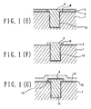
SiO₂ film 4 has been removed by use of NH₄F solution, aSiO₂ film 8 with a thickness of about 20 nm is formed by thermal oxidization in order to remove defects produced on theSi substrate 1 when theSi substrate 1 is etched. - After that, another
SiO₂ film 9 with a thickness of about 1 µm, for instance is further deposited thereon by chemical vapor deposition method as a filling substance of the element separating trench 7 (as a buried element separation). - After that, as shown in Fig. 1(E), the deposited filling substance of
SiO₂ film 9 is etched back by anisotropic etching or polishing by use of the polycrystalline Si film 3 as a stopper film, the etching of the fillingsubstance SiO₂ film 9 can be stopped at a level flush with the polycrystalline Si film 3 to form the buriedelement separating region 10. - Further, as shown in Fig. 1(F), the poly
crystalline Si film 3 used as a stopper during the etching back is removed to complete the buriedelement separating region 10. - Finally, as shown in Fig. 1(G), a poly
crystalline Si film 12 is deposited all over the device to complete a semiconductor device. - The buried
element separating region 10 formed in accordance with the above-mentioned method is of concave shape. In addition, since theedge portion 13 of theSi substrate 1 is covered with theSiO₂ film 9 for filling the buriedelement separating trench 7, it is possible to eliminate electric field concentration and defects at the corner thereof, so that it is possible to realize an LSI of high reliability. - Further, in the above-mentioned first embodiment, the
SiO₂ film 4 is used as a mask for etching theSi substrate 1 to form theelement separating trench 7, and the polycrystalline Si film 3 is used as an etching stopper film when the filling substance of the buriedelement separating region 10 is etched back. Without being limited thereto, however, it is possible to use any other films, as far as the etching mask (used when theSi substrate 1 is etched to form the element separating trench 7) and the etching stopper (used when the filling substance is etched back) are different from each other. For instance, a WSi film, TiN film, carbon film, SiN film, etc, are usable as the etching stopper. - Further, in this first embodiment, the SiO₂ is used as the substance for filling the buried
element separating trench 7. Without being limited only thereto, it is of course possible to use other filling substances such as Si, SiN, etc. - Further, when Si is used as the filling substance, SiO₂ film and SiN film can be used as the poly
crystalline Si film 3 and theSiO₂ film 4, both shown in Fig. 1(A), or vice versa. - Further, in the first embodiment, the poly
crystalline Si film 3 and theSiO₂ film 4 are deposited in sequence; thesefilms resist film 5 formed into a predetermined shape as a mask; and theSiO₂ film 4 is used as a mask to etch theelement separating trench 7. However, it is possible to realize the same structure even when theSiO₂ film 4 is not deposited. - Fig. 2(A) to (C) show a second embodiment of the manufacturing method according to the present invention, which is described from the above-mentioned point of view..
- First, as shown in Fig. 2(A), a
SiO₂ film 2 with a thickness of about 10 nm, for instance is formed on aSi substrate 1 by thermal oxidization. Then, a polycrystalline Si film 3 with a thickness of about 200 nm, for instance is deposited by chemical vapor deposition method. Further, aresist film 5 is applied thereonto and formed into a predetermined shape in accordance with photolithography. - Further, as shown in Fig. 2(B), by using the formed resist
film 5 as a mask, the polycrystalline Si film 3 is processed by anisotropic etching, and further etched by isotropic etching to form a recessedportion 6 with a recess of about 100 nm. As a method of forming the recessedportion 6, CDE method (chemical dry etching), wet processing, etc. are known. In any method, however, it is possible to form the recessedportion 6 as shown in Fig. 2(B). - After that, as shown in Fig. 2(C), the
SiO₂ film 2 is removed to expose the surface of theSi substrate 1, and the exposedSi substrate 1 is etched to a depth of about 500 nm (sufficient depth as the buried element separation) by use of theSiO₂ film 2 as a mask to form anelement separating trench 7. - After that, as shown in Fig. 3A the
SiO₂ film 2 is removed and the process as shown in Fig. 1(D) to (G) are conducted in the same way as with the case of the first embodiment to obtain the semiconductor device. - As described above, in the above-mentioned embodiments, as shown in Fig. 1 (F), after the buried
element separating region 10 has been completed, ions are implanted to control the threshold level to a predetermined value; after theSiO₂ film 2 and theSiO₂ film 8 above the surface of theSi substrate 1 has been removed, agate oxide film 11 with a thickness of about 10 nm is formed by thermal oxidization; and after that, a polycrystalline Si film 12 with a thickness of about 300 nm, for instance is deposited and formed into a predetermined shape as a gate electrode. The device thus obtained is shown in Fig. 1(G). - When the structure shown in Fig. 1(G) is compared with that shown in Fig. 3(D), since the
edge portion 13 is formed into a concave shape as shown in Fig. 1(G), it is possible to solve the problem with the kink characteristics of the MOSFET caused by the electric field concentration at theedge portion 13 of the buriedelement separating region 10 in the conventional semiconductor device. - Further, in the conventional semiconductor device shown in Fig. 3(D), since the
edge portion 13 is located at the corner of theSi substrate 1, a mechanical stress tends to be concentrated and thereby a defect easily occurs, so that a problem arises in that the gate oxide film is leaked. In contrast with this, in the semiconductor device of the present invention as shown in Fig. 1(G), since theedge portion 13 of the buriedelement separating region 10 is formed away from the corner of theSi substrate 1, it is possible to prevent a defect from being produced at theedge portion 13 and thereby to solve the problem related to the gate oxide film leakage. - Further, it is also possible to use a Si nitride film instead of the
SiO₂ films - Further, the
SiO₂ film 2 can be replaced with a carbon film, TiN film, or siliside metal, etc. Further, theSiO₂ film 4 can be replaced with Si oxide film, Si nitride film, Si film, or resist film, etc. Further, theSiO₂ film 8 can be replaced with Si oxide film, Si nitride film, or Si film. - As described above, in the method of manufacturing the semiconductor device according to the present invention, after materials are deposited in sequence on the substrate, a part of the material is recessed in the horizontal direction along the surface of the substrate to form a recessed portion; after that, an element separating trench is formed; another material is deposited; and the whole device is etched back. Therefore, since a convex buried
element separating region 10 can be formed and in addition since the edge portion of the substrate can be covered with the element separating region filling material, it is possible to prevent the electric field from being concentrated at the corner portion of the substrate and to prevent a defect from occurring at the corner portion of the substrate, thus providing miniaturized semiconductor device of higher reliability. - In summary, according to the present invention, since the edge portion of the element separating trench formed in the semiconductor substrate can be covered with the trench filling material, it is possible to provide a semiconductor device which can suppress electric field concentration at the edge portion of the substrate and thereby to prevent the defect from being produced at the edge portion thereof.
Claims (14)
- A method of manufacturing a semiconductor device, comprising the steps of:
forming a first material layer (3) and a second material layer (5) in sequence on a surface of a semiconductor substrate (1);
forming a first opening on the first material layer (3) and a second opening in the second material layer (5), the first opening being larger than the second opening;
forming an element separating trench (7) under the second opening in the substrate (1) by using the second material layer (5) as a mask;
removing the second material layer (5);
depositing a filling material (9) on the element separating trench (7), the substrate (1) and the first material layer (3); and
etching back the filling material (9) by using the first material layer (3) as a stopper. - The method of manufacturing a semiconductor device of claim 1, which further comprises the steps of:
removing the first material layer (3); and
depositing a third material layer (12) on the filling material (9) and the substrate (1). - The method of manufacturing a semiconductor device of claim 2, wherein the first material layer (3) is any one of a poly crystalline silicon layer, a SiO₂ layer, and a SiN layer; the second material layer (5) is a resist film; the third material layer (12) is a poly crystalline silicon film; and the filling material (9) is any of a SiO₂ film and a Si film.
- The method of manufacturing a semiconductor device of claim 3, wherein the first material layer (3) is a SiO₂ layer and the filling material (9) is a SiO₂ film, and further comprises the step of forming a first insulating layer (2) between the substrate (1) and the first material layer (3).
- The method of manufacturing a semiconductor device of claim 3, wherein the first material layer (3) is SiN layer and the filling material (9) is a SiO₂ film.
- A method of manufacturing a semiconductor device, comprising the steps of:
forming a first material layer (3), a second material layer (4), and a third material layer (5) on a surface of a semiconductor substrate (1);
patterning the third material layer (5);
etching the second and the first material layers (4, 3) by using the third material layer (5) as a mask to form a first opening on the first material layer (3) and a second opening in the second material layer (4), the first opening being larger than the second opening;
forming an element separating trench (7) under the second opening in the substrate (1) by using the second material layer (4) as a mask;
removing the second material layer (4);
depositing a filling material (9) on the element separating trench (7), the substrate (1) and the first material layer (3); and
etching back the filling material (9) by using the first material layer (3) as a stopper. - The method of manufacturing a semiconductor device of claim 4, which further comprises the steps of:
removing the first material layer (3); and
depositing a third material layer (12) on the filling material (9) and the substrate (1). - The method of manufacturing a semiconductor device of claim 1 or 6, which further comprises the steps of forming a first insulating layer (2) between the substrate (1) and the first material layer (3).
- The method of manufacturing a semiconductor device of claim 1 or 6, wherein the filling material (9) is deposited via a second insulating layer (8).
- The method of manufacturing a semiconductor device of claim 8, wherein the filling material (9) is deposited via a second insulating layer (8).
- The method of manufacturing a semiconductor device of claim 2 or 7, wherein the third material layer (12) is deposited via a third insulating layer (11).
- The method of manufacturing a semiconductor device of claim 7, wherein the first material layer (3) is any one of a poly crystalline silicon layer, a SiO₂ layer, and a SiN layer; the second material layer (4) is any of a SiO₂ film and a SiN film; the third material layer (5) is a resist film; and the filling material (9) is any of a SiO film and a Si film.
- The method of manufacturing a semiconductor device of claim 12, wherein the first material layer (3) is a poly crystalline silicon layer, the second material layer (4) is a SiO₂ film and the filling material (9) is a SiO₂ film, and further comprises the step of forming a first insulating layer (2) of a SiO₂ film between the substrate (1) and the first material layer (3).
- The method of manufacturing a semiconductor device of claim 12, wherein the first material layer (3) is a poly crystalline silicon layer, the second material layer (4) is a SiN film and the filling material (9) is a SiO₂ film, and further comprises the step of forming a first insulating layer (2) of a SiO₂ film between the substrate (1) and the first material layer (3).
Applications Claiming Priority (3)
| Application Number | Priority Date | Filing Date | Title |
|---|---|---|---|
| JP5333195A JPH07193121A (en) | 1993-12-27 | 1993-12-27 | Production of semiconductor device |
| JP333195/93 | 1993-12-27 | ||
| JP33319593 | 1993-12-27 |
Publications (3)
| Publication Number | Publication Date |
|---|---|
| EP0660389A2 true EP0660389A2 (en) | 1995-06-28 |
| EP0660389A3 EP0660389A3 (en) | 1997-12-29 |
| EP0660389B1 EP0660389B1 (en) | 2002-02-27 |
Family
ID=18263378
Family Applications (1)
| Application Number | Title | Priority Date | Filing Date |
|---|---|---|---|
| EP94120685A Expired - Lifetime EP0660389B1 (en) | 1993-12-27 | 1994-12-27 | Method of manufacturing semiconductor devices having element separating regions |
Country Status (5)
| Country | Link |
|---|---|
| US (1) | US5766823A (en) |
| EP (1) | EP0660389B1 (en) |
| JP (1) | JPH07193121A (en) |
| KR (1) | KR0179681B1 (en) |
| DE (1) | DE69429978T2 (en) |
Cited By (2)
| Publication number | Priority date | Publication date | Assignee | Title |
|---|---|---|---|---|
| FR2792113A1 (en) * | 1999-04-06 | 2000-10-13 | St Microelectronics Sa | Production method of integrated circuit involves shallow trench isolation adjacent to active zone of insulated-gate transistor |
| US6265743B1 (en) | 1997-04-11 | 2001-07-24 | Mitsubishi Denki Kabushiki Kaisha | Trench type element isolation structure |
Families Citing this family (23)
| Publication number | Priority date | Publication date | Assignee | Title |
|---|---|---|---|---|
| JP3688816B2 (en) * | 1996-07-16 | 2005-08-31 | 株式会社東芝 | Manufacturing method of semiconductor device |
| US6114741A (en) * | 1996-12-13 | 2000-09-05 | Texas Instruments Incorporated | Trench isolation of a CMOS structure |
| KR19980051524A (en) * | 1996-12-23 | 1998-09-15 | 김영환 | Device Separation Method of Semiconductor Device |
| KR19980060506A (en) * | 1996-12-31 | 1998-10-07 | 김영환 | Device Separator Formation Method of Semiconductor Device |
| JP3614267B2 (en) * | 1997-02-05 | 2005-01-26 | 株式会社ルネサステクノロジ | Manufacturing method of semiconductor integrated circuit device |
| JPH10223747A (en) * | 1997-02-06 | 1998-08-21 | Nec Corp | Manufacture of semiconductor device |
| US5960297A (en) * | 1997-07-02 | 1999-09-28 | Kabushiki Kaisha Toshiba | Shallow trench isolation structure and method of forming the same |
| US5981356A (en) * | 1997-07-28 | 1999-11-09 | Integrated Device Technology, Inc. | Isolation trenches with protected corners |
| US5837612A (en) * | 1997-08-01 | 1998-11-17 | Motorola, Inc. | Silicon chemical mechanical polish etch (CMP) stop for reduced trench fill erosion and method for formation |
| US6103635A (en) * | 1997-10-28 | 2000-08-15 | Fairchild Semiconductor Corp. | Trench forming process and integrated circuit device including a trench |
| US6054343A (en) * | 1998-01-26 | 2000-04-25 | Texas Instruments Incorporated | Nitride trench fill process for increasing shallow trench isolation (STI) robustness |
| US5976948A (en) * | 1998-02-19 | 1999-11-02 | Advanced Micro Devices | Process for forming an isolation region with trench cap |
| US6214699B1 (en) * | 1998-04-01 | 2001-04-10 | Texas Instruments Incorporated | Method for forming an isolation structure in a substrate |
| KR19990079343A (en) * | 1998-04-03 | 1999-11-05 | 윤종용 | Trench device isolation method for semiconductor devices |
| US6265282B1 (en) * | 1998-08-17 | 2001-07-24 | Micron Technology, Inc. | Process for making an isolation structure |
| JP3540633B2 (en) * | 1998-11-11 | 2004-07-07 | 株式会社東芝 | Method for manufacturing semiconductor device |
| KR20000066999A (en) * | 1999-04-22 | 2000-11-15 | 김영환 | Manufacturing method for isolation in semiconductor device |
| JP2001118920A (en) * | 1999-10-15 | 2001-04-27 | Seiko Epson Corp | Semiconductor device and manufacturing method therefor |
| US6406982B2 (en) * | 2000-06-05 | 2002-06-18 | Denso Corporation | Method of improving epitaxially-filled trench by smoothing trench prior to filling |
| JP2002203894A (en) * | 2001-01-04 | 2002-07-19 | Mitsubishi Electric Corp | Method for manufacturing semiconductor device |
| KR100546852B1 (en) * | 2002-12-28 | 2006-01-25 | 동부아남반도체 주식회사 | Method For Manufacturing Semiconductor Devices |
| US7119403B2 (en) * | 2003-10-16 | 2006-10-10 | International Business Machines Corporation | High performance strained CMOS devices |
| US6905943B2 (en) * | 2003-11-06 | 2005-06-14 | Texas Instruments Incorporated | Forming a trench to define one or more isolation regions in a semiconductor structure |
Citations (3)
| Publication number | Priority date | Publication date | Assignee | Title |
|---|---|---|---|---|
| EP0048175A2 (en) * | 1980-09-17 | 1982-03-24 | Hitachi, Ltd. | Semiconductor device and method of manufacturing the same |
| EP0113517A2 (en) * | 1982-11-29 | 1984-07-18 | Fujitsu Limited | Method for forming an isolation region |
| EP0349107A2 (en) * | 1988-06-30 | 1990-01-03 | Sony Corporation | Semiconductor devices |
Family Cites Families (4)
| Publication number | Priority date | Publication date | Assignee | Title |
|---|---|---|---|---|
| US4666556A (en) * | 1986-05-12 | 1987-05-19 | International Business Machines Corporation | Trench sidewall isolation by polysilicon oxidation |
| US5290664A (en) * | 1990-03-29 | 1994-03-01 | Sharp Kabushiki Kaisha | Method for preparing electrode for semiconductor device |
| US5413966A (en) * | 1990-12-20 | 1995-05-09 | Lsi Logic Corporation | Shallow trench etch |
| JPH0629239A (en) * | 1992-02-27 | 1994-02-04 | Eastman Kodak Co | Manufacture of self-aligned diffused barrier in semiconductor element by making use of lift-off process and semiconductor element provided with diffused barrier |
-
1993
- 1993-12-27 JP JP5333195A patent/JPH07193121A/en active Pending
-
1994
- 1994-12-26 KR KR1019940036760A patent/KR0179681B1/en not_active IP Right Cessation
- 1994-12-27 EP EP94120685A patent/EP0660389B1/en not_active Expired - Lifetime
- 1994-12-27 DE DE69429978T patent/DE69429978T2/en not_active Expired - Lifetime
-
1997
- 1997-09-22 US US08/935,058 patent/US5766823A/en not_active Expired - Lifetime
Patent Citations (3)
| Publication number | Priority date | Publication date | Assignee | Title |
|---|---|---|---|---|
| EP0048175A2 (en) * | 1980-09-17 | 1982-03-24 | Hitachi, Ltd. | Semiconductor device and method of manufacturing the same |
| EP0113517A2 (en) * | 1982-11-29 | 1984-07-18 | Fujitsu Limited | Method for forming an isolation region |
| EP0349107A2 (en) * | 1988-06-30 | 1990-01-03 | Sony Corporation | Semiconductor devices |
Non-Patent Citations (4)
| Title |
|---|
| ANONYMOUS: "Optimized Shallow Trench Isolation Structure and Its Process for Eliminating Shallow Trench Isolation Induced Parasitic Effects." IBM TECHNICAL DISCLOSURE BULLETIN, vol. 34, no. 11, April 1992, NEW YORK, US, pages 276-277, XP000303261 * |
| FAZAN P C ET AL: "A highly manufacturable trench isolation process for deep submicron DRAMs" , INTERNATIONAL ELECTRON DEVICES MEETING 1993. TECHNICAL DIGEST (CAT. NO.93CH3361-3), PROCEEDINGS OF IEEE INTERNATIONAL ELECTRON DEVICES MEETING, WASHINGTON, DC, USA, 5-8 DEC. 1993 , ISBN 0-7803-1450-6, 1993, NEW YORK, NY, USA, IEEE, USA, PAGE(S) 57 - 60 XP000481568 * figure 1 * * |
| ISHIJIMA T ET AL: "A deep-submicron isolation technology with T-shaped oxide (TSO) structure" , INTERNATIONAL ELECTRON DEVICES MEETING 1990. TECHNICAL DIGEST (CAT. NO.90CH2865-4), SAN FRANCISCO, CA, USA, 9-12 DEC. 1990 , 1990, NEW YORK, NY, USA, IEEE, USA, PAGE(S) 257 - 260 XP002044218 * figure 1 * * |
| LECHATON ET AL. : "Dielectric Isolation Using a High Resputtering Deposition. July 1975." IBM TECHNICAL DISCLOSURE BULLETIN, vol. 18, no. 2, July 1975, NEW YORK, US, pages 382-383, XP002017906 * |
Cited By (3)
| Publication number | Priority date | Publication date | Assignee | Title |
|---|---|---|---|---|
| US6265743B1 (en) | 1997-04-11 | 2001-07-24 | Mitsubishi Denki Kabushiki Kaisha | Trench type element isolation structure |
| US6372604B1 (en) | 1997-04-11 | 2002-04-16 | Mitsubishi Denki Kabushiki Kaisha | Method for forming a trench type element isolation structure and trench type element isolation structure |
| FR2792113A1 (en) * | 1999-04-06 | 2000-10-13 | St Microelectronics Sa | Production method of integrated circuit involves shallow trench isolation adjacent to active zone of insulated-gate transistor |
Also Published As
| Publication number | Publication date |
|---|---|
| US5766823A (en) | 1998-06-16 |
| KR0179681B1 (en) | 1999-04-15 |
| DE69429978T2 (en) | 2002-10-02 |
| EP0660389B1 (en) | 2002-02-27 |
| DE69429978D1 (en) | 2002-04-04 |
| EP0660389A3 (en) | 1997-12-29 |
| JPH07193121A (en) | 1995-07-28 |
Similar Documents
| Publication | Publication Date | Title |
|---|---|---|
| US5766823A (en) | Method of manufacturing semiconductor devices | |
| US5677229A (en) | Method for manufacturing semiconductor device isolation region | |
| US5885883A (en) | Methods of forming trench-based isolation regions with reduced susceptibility to edge defects | |
| US8338264B2 (en) | Methods for forming isolation structures for semiconductor devices | |
| US5843839A (en) | Formation of a metal via using a raised metal plug structure | |
| US6482718B2 (en) | Method of manufacturing semiconductor device | |
| US5976948A (en) | Process for forming an isolation region with trench cap | |
| US5882981A (en) | Mesa isolation Refill Process for Silicon on Insulator Technology Using Flowage Oxides as the Refill Material | |
| KR100307651B1 (en) | Manufacturing method of semiconductor device | |
| JP2004039734A (en) | Method of forming element separating film | |
| US6664162B2 (en) | Method of manufacturing capacitor | |
| JP2757919B2 (en) | Method for manufacturing semiconductor device | |
| KR100278883B1 (en) | Shallow trench manufacturing method for isolating semiconductor devices | |
| JPH10242264A (en) | Manufacture of semiconductor device | |
| KR100308198B1 (en) | Method of device isolation for soi integrated circuits | |
| US5930649A (en) | Method of forming device isolating layer of semiconductor device | |
| JPH11251318A (en) | Semiconductor device and manufacture therefor | |
| KR0161727B1 (en) | Element isolation method of semiconductor device | |
| US6833295B2 (en) | Method of manufacturing a semiconductor device | |
| JP3609660B2 (en) | Semiconductor device manufacturing method and semiconductor device | |
| KR100367741B1 (en) | An improved structure of borderless contact and fabricating method thereof | |
| JPH07135308A (en) | Fabrication of semiconductor device | |
| JPH0550138B2 (en) | ||
| KR100223825B1 (en) | Method of forming an element isolation region in a semiconductor device | |
| KR100565749B1 (en) | Isolation structure for semiconductor device and fabricating method thereof |
Legal Events
| Date | Code | Title | Description |
|---|---|---|---|
| PUAI | Public reference made under article 153(3) epc to a published international application that has entered the european phase |
Free format text: ORIGINAL CODE: 0009012 |
|
| 17P | Request for examination filed |
Effective date: 19941227 |
|
| AK | Designated contracting states |
Kind code of ref document: A2 Designated state(s): DE FR GB |
|
| PUAL | Search report despatched |
Free format text: ORIGINAL CODE: 0009013 |
|
| AK | Designated contracting states |
Kind code of ref document: A3 Designated state(s): DE FR GB |
|
| 17Q | First examination report despatched |
Effective date: 19991125 |
|
| GRAG | Despatch of communication of intention to grant |
Free format text: ORIGINAL CODE: EPIDOS AGRA |
|
| GRAG | Despatch of communication of intention to grant |
Free format text: ORIGINAL CODE: EPIDOS AGRA |
|
| GRAH | Despatch of communication of intention to grant a patent |
Free format text: ORIGINAL CODE: EPIDOS IGRA |
|
| GRAH | Despatch of communication of intention to grant a patent |
Free format text: ORIGINAL CODE: EPIDOS IGRA |
|
| REG | Reference to a national code |
Ref country code: GB Ref legal event code: IF02 |
|
| GRAA | (expected) grant |
Free format text: ORIGINAL CODE: 0009210 |
|
| AK | Designated contracting states |
Kind code of ref document: B1 Designated state(s): DE FR GB |
|
| REF | Corresponds to: |
Ref document number: 69429978 Country of ref document: DE Date of ref document: 20020404 |
|
| ET | Fr: translation filed | ||
| PLBE | No opposition filed within time limit |
Free format text: ORIGINAL CODE: 0009261 |
|
| STAA | Information on the status of an ep patent application or granted ep patent |
Free format text: STATUS: NO OPPOSITION FILED WITHIN TIME LIMIT |
|
| 26N | No opposition filed |
Effective date: 20021128 |
|
| PGFP | Annual fee paid to national office [announced via postgrant information from national office to epo] |
Ref country code: FR Payment date: 20101224 Year of fee payment: 17 |
|
| PGFP | Annual fee paid to national office [announced via postgrant information from national office to epo] |
Ref country code: GB Payment date: 20101222 Year of fee payment: 17 |
|
| PGFP | Annual fee paid to national office [announced via postgrant information from national office to epo] |
Ref country code: DE Payment date: 20101222 Year of fee payment: 17 |
|
| GBPC | Gb: european patent ceased through non-payment of renewal fee |
Effective date: 20111227 |
|
| REG | Reference to a national code |
Ref country code: FR Ref legal event code: ST Effective date: 20120831 |
|
| REG | Reference to a national code |
Ref country code: DE Ref legal event code: R119 Ref document number: 69429978 Country of ref document: DE Effective date: 20120703 |
|
| PG25 | Lapsed in a contracting state [announced via postgrant information from national office to epo] |
Ref country code: GB Free format text: LAPSE BECAUSE OF NON-PAYMENT OF DUE FEES Effective date: 20111227 Ref country code: DE Free format text: LAPSE BECAUSE OF NON-PAYMENT OF DUE FEES Effective date: 20120703 |
|
| PG25 | Lapsed in a contracting state [announced via postgrant information from national office to epo] |
Ref country code: FR Free format text: LAPSE BECAUSE OF NON-PAYMENT OF DUE FEES Effective date: 20120102 |