EP0660322B1 - Optical disc player and processing method for reproduction data of the optical disc player - Google Patents
Optical disc player and processing method for reproduction data of the optical disc player Download PDFInfo
- Publication number
- EP0660322B1 EP0660322B1 EP94402987A EP94402987A EP0660322B1 EP 0660322 B1 EP0660322 B1 EP 0660322B1 EP 94402987 A EP94402987 A EP 94402987A EP 94402987 A EP94402987 A EP 94402987A EP 0660322 B1 EP0660322 B1 EP 0660322B1
- Authority
- EP
- European Patent Office
- Prior art keywords
- subcode
- signal
- reproduction data
- reproduction
- output
- Prior art date
- Legal status (The legal status is an assumption and is not a legal conclusion. Google has not performed a legal analysis and makes no representation as to the accuracy of the status listed.)
- Expired - Lifetime
Links
Images


Classifications
-
- G—PHYSICS
- G11—INFORMATION STORAGE
- G11B—INFORMATION STORAGE BASED ON RELATIVE MOVEMENT BETWEEN RECORD CARRIER AND TRANSDUCER
- G11B20/00—Signal processing not specific to the method of recording or reproducing; Circuits therefor
- G11B20/10—Digital recording or reproducing
-
- G—PHYSICS
- G11—INFORMATION STORAGE
- G11B—INFORMATION STORAGE BASED ON RELATIVE MOVEMENT BETWEEN RECORD CARRIER AND TRANSDUCER
- G11B27/00—Editing; Indexing; Addressing; Timing or synchronising; Monitoring; Measuring tape travel
- G11B27/10—Indexing; Addressing; Timing or synchronising; Measuring tape travel
- G11B27/19—Indexing; Addressing; Timing or synchronising; Measuring tape travel by using information detectable on the record carrier
- G11B27/28—Indexing; Addressing; Timing or synchronising; Measuring tape travel by using information detectable on the record carrier by using information signals recorded by the same method as the main recording
- G11B27/30—Indexing; Addressing; Timing or synchronising; Measuring tape travel by using information detectable on the record carrier by using information signals recorded by the same method as the main recording on the same track as the main recording
- G11B27/3027—Indexing; Addressing; Timing or synchronising; Measuring tape travel by using information detectable on the record carrier by using information signals recorded by the same method as the main recording on the same track as the main recording used signal is digitally coded
- G11B27/3063—Subcodes
-
- G—PHYSICS
- G11—INFORMATION STORAGE
- G11B—INFORMATION STORAGE BASED ON RELATIVE MOVEMENT BETWEEN RECORD CARRIER AND TRANSDUCER
- G11B20/00—Signal processing not specific to the method of recording or reproducing; Circuits therefor
- G11B20/10—Digital recording or reproducing
- G11B20/10527—Audio or video recording; Data buffering arrangements
-
- G—PHYSICS
- G11—INFORMATION STORAGE
- G11B—INFORMATION STORAGE BASED ON RELATIVE MOVEMENT BETWEEN RECORD CARRIER AND TRANSDUCER
- G11B20/00—Signal processing not specific to the method of recording or reproducing; Circuits therefor
- G11B20/10—Digital recording or reproducing
- G11B20/14—Digital recording or reproducing using self-clocking codes
- G11B20/1403—Digital recording or reproducing using self-clocking codes characterised by the use of two levels
-
- G—PHYSICS
- G11—INFORMATION STORAGE
- G11B—INFORMATION STORAGE BASED ON RELATIVE MOVEMENT BETWEEN RECORD CARRIER AND TRANSDUCER
- G11B2220/00—Record carriers by type
- G11B2220/20—Disc-shaped record carriers
- G11B2220/21—Disc-shaped record carriers characterised in that the disc is of read-only, rewritable, or recordable type
- G11B2220/213—Read-only discs
-
- G—PHYSICS
- G11—INFORMATION STORAGE
- G11B—INFORMATION STORAGE BASED ON RELATIVE MOVEMENT BETWEEN RECORD CARRIER AND TRANSDUCER
- G11B2220/00—Record carriers by type
- G11B2220/20—Disc-shaped record carriers
- G11B2220/25—Disc-shaped record carriers characterised in that the disc is based on a specific recording technology
- G11B2220/2525—Magneto-optical [MO] discs
- G11B2220/2529—Mini-discs
-
- G—PHYSICS
- G11—INFORMATION STORAGE
- G11B—INFORMATION STORAGE BASED ON RELATIVE MOVEMENT BETWEEN RECORD CARRIER AND TRANSDUCER
- G11B2220/00—Record carriers by type
- G11B2220/20—Disc-shaped record carriers
- G11B2220/25—Disc-shaped record carriers characterised in that the disc is based on a specific recording technology
- G11B2220/2537—Optical discs
- G11B2220/2545—CDs
-
- G—PHYSICS
- G11—INFORMATION STORAGE
- G11B—INFORMATION STORAGE BASED ON RELATIVE MOVEMENT BETWEEN RECORD CARRIER AND TRANSDUCER
- G11B7/00—Recording or reproducing by optical means, e.g. recording using a thermal beam of optical radiation by modifying optical properties or the physical structure, reproducing using an optical beam at lower power by sensing optical properties; Record carriers therefor
- G11B7/08—Disposition or mounting of heads or light sources relatively to record carriers
- G11B7/09—Disposition or mounting of heads or light sources relatively to record carriers with provision for moving the light beam or focus plane for the purpose of maintaining alignment of the light beam relative to the record carrier during transducing operation, e.g. to compensate for surface irregularities of the latter or for track following
- G11B7/0946—Disposition or mounting of heads or light sources relatively to record carriers with provision for moving the light beam or focus plane for the purpose of maintaining alignment of the light beam relative to the record carrier during transducing operation, e.g. to compensate for surface irregularities of the latter or for track following specially adapted for operation during external perturbations not related to the carrier or servo beam, e.g. vibration
Definitions
- the present invention relates to a disc player for reproducing a digital audio disc called a compact disc (CD) or a mini disc (MD) and reproducing an information-recorded disc such as a CD-ROM disc (the discs are hereinafter generically referred to simply as discs) and, more particularly, to a disc player having a constitution in which reproduction data read from a disc are stored in a large-capacity memory to be read for output, and to a method of processing the reproduction data.
- CD digital audio disc
- MD mini disc
- CD-ROM disc the discs are hereinafter generically referred to simply as discs
- a disc player having a constitution in which reproduction data read from a disc are stored in a large-capacity memory to be read for output, and to a method of processing the reproduction data.
- Some disc players such as a CD player have an anti-shock constitution for preventing, by assuring continuity of PCM (Pulse Code Modulation) data, a so-called sound skip from occurring when a so-called track jump caused by an external disturbance such as an undue vibration or shock is applied to the player during a disc playback operation.
- PCM Pulse Code Modulation
- track jump denotes that an information reading light spot projected from an optical pick-up for reading recorded information by tracing a record track (a pit train) on a disc jumps off over a track or tracks.
- a data rate of reproducing data from a disc is substantially the same as a data rate of ultimate audio output.
- a disc rotates at a speed, for example, about twice as high as a speed of disc rotation in the ordinary disc player, thereby reading recorded PCM data at an accordingly higher speed than a data reading speed of the ordinary disc player.
- the PCM data thus read are temporarily stored in a large-capacity DRAM (Dynamic Random Access Memory) and are read from the DRAM at the reproducing data rate of the ordinary disc player for output.
- DRAM Dynamic Random Access Memory
- the information reading light spot of the pick-up is returned to a position immediately before a position at which the track jump occurred, restarting reproduction from the former position.
- the PCM data is established based on a subcode synchronizing signal having wow caused by a spindle-drive motor, a data determination signal comes to have wow, making it uncertain where in a one subcode frame the data is established. Consequently, it is required to set a window for one frame jitter margin in which the PCM data coming from the disc is compared with the PCM data coming from the DRAM for a match to perform sound linking processing on the PCM data.
- Document EP-A-0 563 922 discloses a data processing circuit for a disc player, wherein time base connected subcode delimit information is used for settling the time base position of the PCM audio data when a linking process is executed for the PCM audio data upon occurrence of a track jump in a shock-proof CD player.
- a disc player constituted to write reproduction data from a disc to a large-capacity memory and then read said reproduction data from said large-capacity memory for output, comprising subcode signal processing means, characterized in that said subcode signal processing means comprises: jitter detecting means for detecting an amount of jitter contained in a second clock synchronized with said reproduction data as opposed to a first clock of a fixed frequency; counting means for counting said second clock for 98 frames; algebraically adding means for algebraically adding said amount of jitter to a count output of said counting means; offset means for giving a time offset of a predetermined number of frames to an output of said algebraically adding means; match detecting means for detecting a match by a predetermined number of times successively between a reproduction subcode synchronizing signal obtained from said reproduction data and said count output of said counting means; and output determining means for making valid said output of said offset means only when said match detecting means has found said match; wherein there is further provided in
- a reproduction data processing method for a disc player constituted to write reproduction data from a disc to a large capacity memory and then read said reproduction data from said large capacity memory for output, characterized in that the method comprises the steps of: (a) detecting an amount of jitter contained in a second clock synchronized with said reproduction data as opposed to a first clock of a fixed frequency ; (b) counting said second clock for 98 frames ; (c) algebraically adding said amount of jitter to a count output of step (b); (d) giving a time offset of a predetermined number of frames to an output of step (c); (e) detecting a match by a predetermined number of times successively between a reproduction subcode synchronizing signal obtained from said reproduction data and said count output of step (b) ; (f) making valid said output of step (d) only when said match has been detected in step (e); and (g) detecting a sound overleap by reading time information of a subcode contained
- a reproduction data processing method characterized in that it further comprises the steps of: accessing said finally established address upon detection of a sound overleap; comparing said finally established address with said time information of said subcode read in synchronization with said reproduction subcode synchronizing signal; and if a match is found between said time information of said subcode and said finally established address, starting to write said reproduction data to said large capacity memory based on said subcode synchronizing signal.
- the present invention applies to a disc player characterized in that it comprises an eight-to-fourteen modulation demodulating means for demodulating a radio frequency signal and the like coming from an optical pick-up device; first storage means for storing a signal coming from said eight-to-fourteen modulation demodulating means; error correcting means for correcting an error of said signal stored in said first storage means and outputting the corrected signal to said first storage means; deinterleaving means for deinterleaving said signal coming from said first storage means; spindle servo signal processing means for controlling a spindle-drive motor in accordance with a signal coming from said deinterleaving means; a microcomputer; and an electric shock-proof controller for capturing the signal coming from said deinterleaving means to detect for signal drop, said electric shock-proof controller being connected to second storage means and said microcomputer, wherein said subcode signal processing means captures the signal coming from said eight-to-fourteen modulation demodulating means to output a subcode signal; and said microcomputer checks said subcode signal
- the time information of the reproduction data to be written to the large-capacity memory is stored in a memory provided to store the time information, thereby providing the time information of the reproduction data. Consequently, it is unnecessary to perform processing of time conversion while monitoring a storage amount of the large-capacity memory, which is required conventionally, thereby mitigating a software load of a microcomputer used in the system and implementing real-time display of the time information.
- the time information is stored in the memory in a thinned out manner.
- addresses of the memory are made common with upper addresses of the large-capacity memory to link the reproduction data with its time information.
- This set-up provides the time information of the reproduction data with a minimum memory capacity.
- the subcode synchronizing signal synchronized with the fixed clock is generated and, if no sound overleap has been detected, the generated subcode synchronizing signal is used to establish reproduction data to be stored in the large-capacity memory.
- reproduction data processing method if a sound overleap occurs, writing of the reproduction data to the large-capacity memory starts based on the generated subcode synchronizing signal, thereby implementing sound linking on the time axis. Consequently, if reproduction data at a sound linking point is processed with previous-value hold or interpolation, sounds can be linked without error. Also, in software in which fixed patterns continue, sounds can be linked correctly.
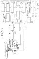
- FIG. 1 there is shown a block diagram illustrating a constitution of a control system of a CD player practiced as one preferred embodiment of the invention.
- a disc (CD) 1 is driven in rotation by a spindle-drive motor 2.
- Information recorded on the disc is read with an optical pick-up 3 (hereinafter referred to simply as a pick-up).
- the pick-up 3 comprises a laser diode 4, an objective lens 5 for focusing a laser beam coming from the laser diode 4 onto a signal recorded side of the disc 1 as an information reading light spot, a polarized beam splitter 6 for changing a direction in which a reflected light beam coming from the disc 1 goes, and a photo detector 7 for receiving the reflected light beam.
- the pick-up 3 is moved in the radial direction of the disc 1 by a thread feed motor, not shown.
- the pick-up 3 further contains a tracking actuator, not shown, for deflecting the information reading light spot in the disc radial direction relative to a record track provided on the disc 1 and a focus actuator, not shown, for moving the objective lens 5 in its optical axis direction.
- An output signal of the pick-up 3 is converted by an I(current)/V(voltage) amplifier 8 from current signal to a voltage signal.
- the resultant voltage signal is shaped by an RF equalizer 9 to be fed to a DSP (Digital Signal Processor) circuit 10.
- DSP Digital Signal Processor
- Signal processing in the DSP circuit 10 is performed as follows. First, asymmetry correction is performed in a PLL (Phase Locked Loop) asymmetry correction circuit 11 to provide a binary signal. Based on an edge of the binary signal, continuous reproduction clock signals are generated according to a constitution of the PLL.
- PLL Phase Locked Loop
- the term "asymmetry” herein denotes a state in which the center of an eye pattern of an RF signal deviates from the center of oscillation.
- EFM Eight-to-Fourteen Modulation
- SCOR subcode synchronizing signal
- the PCM data after EFM demodulation is stored in a RAM (Random Access Memory) 14 once, error-corrected in an error correction circuit 15 based on an error correction and detection parity, and deinterleaved of CIRC (Cross Interleave Reed-Solomon Code) in a deinterleave circuit 16.
- the DSP circuit 10 contains a clock generator 17 for generating a system clock signal based on an output of a crystal resonator 21 and performs signal processing based on the generated system clock.
- a reproduction clock signal generated in the PLL asymmetry correction circuit 11 as a write clock signal WFCK is used, and the above-mentioned system clock signal is used as a read clock signal RFCK.
- the PCM data passed through the DSP circuit 10 is stored in a large-capacity DRAM 23 via an ESP (Electric Shock Proof) controller 22.
- the PCM data stored in the DRAM 23 is read through the ESP controller 22.
- the read PCM data is then filtered by a digital filter 24, converted by a D/A converter 25 to analog data, and outputted as L-channel and R-channel audio outputs.
- the DRAM 23 is used to assure continuity of the PCM data to prevent sound overleap from occurring when a track jump has taken place due to an external disturbance such as an undue shock during playback.
- the microcomputer returns the information reading light spot of the pick-up 3 to a position at which the spot was projected immediately before the occurrence of the track jump to restart the reproduction, while the ESP controller 22 links the PCM data to be obtained after the restart of the reproduction with the PCM data stored in the DRAM 23 that was present immediately before the occurrence of the track jump.
- a specific constitution and function of the ESP controller 22 will be described later in more detail.
- the DSP circuit 10 is provided with a spindle servo signal processing circuit 18 for controlling the rotation of the spindle-drive motor 2 based on a phase difference between a reference clock signal and the reproduction clock signal.
- An optical- system servo signal processing circuit 26 controls servo systems associated with operation of the pick-up 3: that is, a tracking servo system for making the information light spot follow the track on the disc 1; a focus servo system for keeping the light spot always focused on the signal recorded surface of the disc 1; and a thread servo system for controlling the position of the pick-up 3 in the radial direction of the disc 1.
- the spindle servo signal processing circuit 18 drives, normally in a low-speed mode, the spindle-drive motor 2 for rotating the disc 1, and when a track jump occurs, drives the spindle-drive motor 2 in a high-speed mode.
- the spindle servo signal processing circuit 18 drives the spindle-drive motor 2 in the low speed mode again.
- the spindle-drive motor 2 is driven at a normal rotational speed of a CD player (or a normal speed).
- the spindle-drive motor 2 is driven at a speed twice as high for example.
- the ESP controller 22 controls PCM data read/write operations on the DRAM 23. Addresses for accessing data stored in the DRAM 23 include a data read address RA and a data write address WA.
- the data read address RA is incremented based on a clock signal generated inside the ESP controller 22, while the data write address WA is incremented based on a clock signal outputted from the DSP circuit 10.
- PCM data written to the DRAM 23 based on the clock signal coming from the DSP circuit is not always correct. Therefore, it is required to check a subcode or the like of the PCM data for a sound overleap.
- the microcomputer 20 checks a Q channel (hereinafter referred to as a subcode Q) of a subcode supplied from the subcode processing circuit 13 of the DSP circuit 10 for a sound overleap caused by a track jump due to external disturbance such as a shock or a vibration.
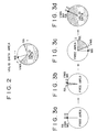
- the ESP controller Upon receiving an output from the microcomputer 20 indicating detection of no sound overleap, the ESP controller updates a last address of the PCM data written to the DRAM 23 as a valid (or established) address VWA. Namely, referring to Fig. 2, an area between the valid address VWA and the read address RA is a data area having no sound overleap. The data in this area is handled as valid data.
- Fig. 3 there is shown a relationship between the read address RA, the write address WA, and the valid address VWA in the DRAM 23.
- the write address WA advances starting from an initial state of Fig. 3 (a) twice as fast as the read address RA, data is written by the write address WA, registered by the valid address VWA, and sequentially read by the read address RA (Fig. 3 (b)).
- the write address WA eventually catches up the read address RA by passing a state of Fig. 3 (c).
- the write operation is disabled (Fig. 3 (d)).
- the ESP controller goes back to the last valid address.
- the microcomputer 20 returns the pick-up 3 to the position immediately before the position at which the track jump has occurred to restart the reproduction from that position and, at the same time, reads the subcode Q at the rising of the reproduction subcode synchronizing signal SCOR to compare the subcode Q with data relating to the last valid address, the latter data being held in the microcomputer itself. Then, if a match is found between the compared data, the ESP controller 22 restarts the writing in the DRAM 23 when a subcode synchronizing signal GRSCOR, to be generated within 2.45 ms to 6.23 ms, is at HIGH level; the signal GRSCOR is to be described later.
- GRSCOR subcode synchronizing signal
- the ESP controller 22 is provided with a subcode synchronizing signal generator for generating the subcode synchronizing signal GRSCOR free of the wow caused by the spindle-drive motor 2.
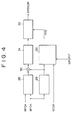
- Fig. 4 shows an example of constitution of this subcode synchronizing signal generator.
- a jitter counter 28 measures a jitter amount of the write clock signal WFCK or the reproduction clock signal coming from the disc 1 as opposed to the read clock signal RFCK or the fixed clock signal.
- a reference counter 29 counts the cycles of the write clock signal WFCK for 98 frames.
- a count output of the reference counter 29 is added to or subtracted from the jitter amount measured by the jitter counter 28.
- an offset of 64 frames for example is given to the addition/subtraction output, by an offset circuit 31.
- subtracting (or adding) the measured jitter amount from the count output of the write clock WFCK for 98 frames, and applying a correction in time axis to the reproduction subcode synchronizing signal SCOR containing the wow caused by the spindle-drive motor can eliminate the wow from the reproduction subcode synchronizing signal SCOR, thereby generating the subcode synchronizing signal GRSCOR synchronized with the PCM data read from the DRAM 23 based on the read clock RFCK having a crystal resonator precision.
- a match detector 33 detects a match between the reproduction subcode synchronizing signal SCOR coming from the DSP circuit 10 and the count output of the reference counter 29. If the match is found twice consecutively for example as shown in Fig. 5, the match detector 33 sends a match detect signal GSS to an output determination circuit 32 and is locked. Upon reception of the match detect signal GSS, or when the match between the reproduction subcode synchronizing signal SCOR and the count output of the reference counter has been found twice consecutively, the output determination circuit 32 outputs the generated subcode synchronizing signal GRSCOR.
- the match detector 33 is locked, the match detector is thereafter kept locked until a reset signal comes from the microcomputer 20 or a signal GTOP to be outputted when a frame sync signal is resynchronized by the DSP circuit 10 goes HIGH level. While the match detector 33 is locked, subcode synchronizing signal GRSCOR is kept outputted. When the RAM 14 of the DSP circuit 10 overflows, the ESP controller 22 once resets the read clock RFCK and the measured jitter amount of the write clock WFCK to perform the measurement again.
- Fig. 6 shows a timing chart obtained when a frame jitter margin (FJM) is ⁇ 0 in a subcode synchronizing signal generator having the above-mentioned constitution.
- FJM frame jitter margin
- the reference counter 29 counts 98 frames because the reproduction subcode synchronizing signal (SCOR) has a pulse every 98 frames. Obviously, in a system where the reproduction subcode synchronizing signal had a pulse after a different number of frames, e.g. every N frames, the reference counter 29 would count N frames.
- the microcomputer 20 accesses a position immediately preceding the occurrence of a track jump, compares data regarding the last valid address of the DRAM 23 (this data being present at the microcomputer 20) with the subcode Q being read from the disc 1, and determines a point for sound linking. That is, the microcomputer 20 must determine whether to perform sound linking or not by reading the subcode Q at the rising of the reproduction subcode synchronizing signal SCOR and comparing the read subcode Q with the data regarding the last valid DRAM address.
- a time between the rising of the reproduction subcode synchronizing signal SCOR and the rising of the subcode synchronizing signal GRSCOR is a minimum of 2.45 ms and a maximum of 6.23 ms. Namely, in sound linking, it is most critical for the microcomputer 20 when the frame jitter margin is -28 frames. During this 2.45 ms, the microcomputer must read the subcode Q to compare it with the data relating to the last established address of the DRAM 23 to determine whether to perform sound linking or not.
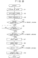
- step S1 Upon detection of the rising of the reproduction subcode synchronizing signal SCOR (step S1), the microcomputer 20 activates a built-in timer (step S2) and reads the subcode Q (step S3).
- the microcomputer compares a difference between the read subcode Q and the previously established address to determine whether a sound overleap has taken place or not (step S4). If the sound overleap has been detected, the microcomputer 20 passes control to a sound linking routine to be described later. If no sound overleap has been detected, the microcomputer 20 monitors the rising of the subcode synchronizing signal GRSCOR (step S5). Upon detection of the rising of the subcode synchronizing signal GRSCOR, the microcomputer 20 determines, based on a time measured by the above-mentioned timer, whether the subcode synchronizing signal GRSCOR has come between 2.45 ms and 6.23 ms (step S6).
- the microcomputer 20 passes control to the sound linking routine. If the GRSCOR has come during that period of time, then the microcomputer 20 sends a registration permit signal XQOK to the ESP controller 22 while the subcode synchronizing signal GRSCOR is HIGH (about 68 ( ⁇ s) (step S7)). When the registration permit signal XQOK has come to the ESP controller 22 while the subcode synchronizing signal GRSCOR is HIGH, the ESP controller 22 loads the write address WA in the valid address VWA to establish the data. It should be noted here that a point to be established by the ESP controller is always fixed within one subcode frame as shown in Fig. 10.
- the microcomputer 20 then sends a confirmation request signal XSOE to the ESP controller 22 to confirm whether the registration has been made correctly (step S8).
- the ESP controller 22 returns a registration complete signal QRCVD of HIGH level in response to the XSOE signal.
- the microcomputer 20 waits for the return of the QRCVD signal from the ESP controller 22 (step S9). If the QRCVD is not HIGH, the microcomputer 20 passes control to the sound linking routine. If the QRCVD is HIGH, the microcomputer 20 updates the valid address VWA (step S10), thereby ending the series of processing operations for the data establishment.
- a write enable signal, XWRE when at a LOW level enables the writing of data to the DRAM 23.
- the microcomputer 20 makes HIGH the write enable signal XWRE, thereby disabling the writing (step S11).
- the microcomputer 20 accesses the final valid address VWA it holds (step S12) and sends a SCOR resynchronizing signal GRSRST to the ESP controller 22 (step S13).
- the match detector 33 of the subcode synchronizing signal generator (Fig. 4) is reset by the SCOR resynchronizing signal GRSRST.
- step S14 upon detection of the rising of the reproduction subcode synchronizing signal SCOR (step S14), the microcomputer 20 activates the incorporated timer (step S15) to read the subcode Q (step S16). Then, the microcomputer 20 determines whether the subcode Q matches the final valid address VWA (step S17). If no match is found, the microcomputer returns to step S14 to repeat the above-mentioned processing operations.
- the microcomputer 20 monitors the rising of the subcode synchronizing signal GRSCOR (step S18). Upon detection of the rising of the subcode synchronizing signal GRSCOR, the microcomputer 20 determines, based on the time measured by the timer, whether the subcode synchronizing signal GRSCOR has come within a period of time between 2.45 ms and 6.23 ms (step S19). If the subcode synchronizing signal GRSCOR has not come within the period of time between 2.45 ms and 6.23 ms, the microcomputer returns to step S12 to repeat the above-mentioned processing operations.
- the microcomputer 20 makes LOW the above-mentioned write enable signal XWRE while the subcode synchronizing signal GRSCOR is HIGH, thereby permitting the ESP controller to write the data to the DRAM 23 (step S20).
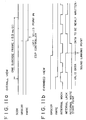
- This causes the ESP controller 22 to start writing the PCM data read from the disc 1 to the DRAM 23 when the established point of the subcode frame has been reached as shown in Fig. 11.
- Fig. 12 shows a timing chart describing the series of operations ranging from the detection of sound overleap to the sound linking.
- the ESP controller 22 incorporates a RAM 27 dedicated to the subcode Q as shown in Fig. 1.
- This RAM is provided to store the time information of reproduction data.
- the time information to be stored in the RAM 27 are thinned out to some extent in the present embodiment. In what follows, the thinning out will be described on the supposition that the external DRAM 23 has a storage capacity of 16M (i.e. 16 x 2 20 ) bits.
- linking PCM data with its time information by making the upper address of the external DRAM 23 common with the address of the incorporated RAM 27 allows the microcomputer 20 to correct the subcode Q in time axis by means of two operations; sending the time information of the PCM data being read from the disc 1 to the ESP controller 22 and reading the time information from the ESP controller 22.
- the microcomputer 20 performs the time information conversion while monitoring the storage capacity of the DRAM 23 for displaying resultant data, thereby increasing the load of the microcomputer 20.
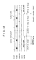
- the writing of the subcode Q to the incorporated RAM is performed while a write enable signal MWE is HIGH (13.3 ms/2) as shown in Fig. 13.
- the one-byte data TNO, IND, MIN, and SEC are put on serial I/F data, clock, and latch to be written in four time intervals with the least significant bit (LSB) first.
- the reading of the subcode Q from the RAM 27 is performed while the read enable signal MRE is HIGH (13.3 ms/2) as shown in Fig. 14.
- a LOW level pulse is sent 32 times as a read clock QRCK to read the TNO, IND, MIN, and SEC from a subcode Q output terminal QTBC with the LSB first.
- the present invention has been described as applied to a CD player. It will be apparent to those skilled in the art that the present invention is not restricted to the CD player; instead, the present invention is applicable to other type of disc players such as those for reproducing an MD or a CD-ROM disc.
- an amount of jitter contained in a write clock synchronized with a reproduction clock as opposed to a read clock synchronized with a fixed clock is detected, the detected jitter amount is added to or subtracted from a count output obtained by counting the write clock for 98 frames and an offset for the predetermined number of frames is given to an addition/subtraction result to generate a subcode synchronizing signal completely synchronized with the read clock, based on which subcode synchronizing signal reproduction data is written to a large-capacity memory.
- This constitution implements data establishment on the time axis and sound linking on the time axis, so that, if the reproduction data at a sound linking point is processed with previous-value hold or interpolation, the sound linking can be performed without error and, in software having successive fixed patterns, correct sound linking is assured.
- a reproduction subcode synchronizing signal read from a disc is compared with a count output of a write clock and, only when a match is found by the predetermined number of times successively, a generated subcode synchronized signal is made valid.
- This constitution eliminates a false reproduction subcode synchronizing signal caused by a scratch or the like on the disc and determines a true reproduction subcode synchronizing signal, thereby enabling to generate the subcode synchronizing signal without being affected by the scratch or the like on the disc.
- time information of reproduction data to be written to a large-capacity memory is stored in a memory for storing the time information.
- the stored time information makes it unnecessary to perform a time converting operation while monitoring the storage capacity of the large-capacity memory, thereby mitigating the load placed on microcomputer software and permitting the display of the time information in real-time.
- the time information is stored in the memory for storing the time information in a thinned-out manner to restrict a capacity of this memory to a minimum, thereby providing the time information of reproduction data at a relatively low cost.
- a subcode synchronizing signal synchronized with a read clock is generated. Therefore, if no sound overleap has occurred, the generated subcode synchronizing signal is used to establish reproduction data to be stored in the large-scale memory, thereby permitting data establishment by time axis. Further, according to the invention, if a sound overleap has occurred, writing of the reproduction data to the large-capacity memory is started on the basis of the generated subcode synchronizing signal, thereby implementing sound linking on the time axis. Consequently, even if the reproduction data at a sound linking point is processed with previous-value hold or interpolation, the sound linking can be performed without involving an error and, in software having fixed patterns successively, sounds can be linked correctly.
Landscapes
- Engineering & Computer Science (AREA)
- Signal Processing (AREA)
- Multimedia (AREA)
- Signal Processing For Digital Recording And Reproducing (AREA)
Description
- The present invention relates to a disc player for reproducing a digital audio disc called a compact disc (CD) or a mini disc (MD) and reproducing an information-recorded disc such as a CD-ROM disc (the discs are hereinafter generically referred to simply as discs) and, more particularly, to a disc player having a constitution in which reproduction data read from a disc are stored in a large-capacity memory to be read for output, and to a method of processing the reproduction data.
- Some disc players such as a CD player have an anti-shock constitution for preventing, by assuring continuity of PCM (Pulse Code Modulation) data, a so-called sound skip from occurring when a so-called track jump caused by an external disturbance such as an undue vibration or shock is applied to the player during a disc playback operation. The term "track jump" as used herein denotes that an information reading light spot projected from an optical pick-up for reading recorded information by tracing a record track (a pit train) on a disc jumps off over a track or tracks.
- In an ordinary CD player, or a CD player that is not shock-proofed, a data rate of reproducing data from a disc is substantially the same as a data rate of ultimate audio output. On the contrary, in a shock-proof CD player, a disc rotates at a speed, for example, about twice as high as a speed of disc rotation in the ordinary disc player, thereby reading recorded PCM data at an accordingly higher speed than a data reading speed of the ordinary disc player. The PCM data thus read are temporarily stored in a large-capacity DRAM (Dynamic Random Access Memory) and are read from the DRAM at the reproducing data rate of the ordinary disc player for output.
- If a track jump occurs during disc reproduction, the information reading light spot of the pick-up is returned to a position immediately before a position at which the track jump occurred, restarting reproduction from the former position. Since the PCM data is established based on a subcode synchronizing signal having wow caused by a spindle-drive motor, a data determination signal comes to have wow, making it uncertain where in a one subcode frame the data is established. Consequently, it is required to set a window for one frame jitter margin in which the PCM data coming from the disc is compared with the PCM data coming from the DRAM for a match to perform sound linking processing on the PCM data.
- However, in the above-mentioned conventional disc player, if a track jump occurs due to an external disturbance such as undue vibration or shock, the sound linking processing is made by comparing the PCM data, thereby involving following problems:
- (1) When it is attempted to perform linking processing on software having successive fixed patterns, the match is found as soon as the data entered the comparison window, thereby making it highly possible to link sounds at a point at which no sound lining should occur; and
- (2) If either PCM data coming from the DRAM or PCM data coming from the disc is processed with error correction such as previous-value hold and interpolation, linking processing cannot be performed on the PCM data, thereby making it possible that sounds are not linked for ever.
-
- Document EP-A-0 563 922 discloses a data processing circuit for a disc player, wherein time base connected subcode delimit information is used for settling the time base position of the PCM audio data when a linking process is executed for the PCM audio data upon occurrence of a track jump in a shock-proof CD player.
- It is therefore an object of the present invention to provided a disc player and a processing method of reproduction data used on the disc player, the disc player being capable of correctly performing sound linking processing on software having successive fixed patterns and implementing sound linking without involving an error if PCM data at a sound linking point is processed with previous-value hold or interpolation for error correction.
- In carrying out the invention and according to one aspect thereof, there is provided a disc player constituted to write reproduction data from a disc to a large-capacity memory and then read said reproduction data from said large-capacity memory for output, comprising subcode signal processing means, characterized in that said subcode signal processing means comprises: jitter detecting means for detecting an amount of jitter contained in a second clock synchronized with said reproduction data as opposed to a first clock of a fixed frequency; counting means for counting said second clock for 98 frames; algebraically adding means for algebraically adding said amount of jitter to a count output of said counting means; offset means for giving a time offset of a predetermined number of frames to an output of said algebraically adding means; match detecting means for detecting a match by a predetermined number of times successively between a reproduction subcode synchronizing signal obtained from said reproduction data and said count output of said counting means; and output determining means for making valid said output of said offset means only when said match detecting means has found said match; wherein there is further provided in the disc player means for detecting a sound overleap by reading, in synchronization with a reproduction subcode synchronizing signal obtained from said reproduction data, time information of a subcode contained in said reproduction data, and by using said time information and a finally established address of said large capacity memory; wherein said time offset is adapted to compensate for time spent detecting a sound overleap, the duration of said time offset being such that the total of the maximum jitter margin and the time offset is less than one subcode frame; and wherein writing of said reproduction data to said large-capacity memory is conditional upon the timing of pulses in the output of said offset means.
- In carrying out the invention and according to another aspect thereof, there is provided a reproduction data processing method for a disc player constituted to write reproduction data from a disc to a large capacity memory and then read said reproduction data from said large capacity memory for output, characterized in that the method comprises the steps of: (a) detecting an amount of jitter contained in a second clock synchronized with said reproduction data as opposed to a first clock of a fixed frequency ; (b) counting said second clock for 98 frames ; (c) algebraically adding said amount of jitter to a count output of step (b); (d) giving a time offset of a predetermined number of frames to an output of step (c); (e) detecting a match by a predetermined number of times successively between a reproduction subcode synchronizing signal obtained from said reproduction data and said count output of step (b) ; (f) making valid said output of step (d) only when said match has been detected in step (e); and (g) detecting a sound overleap by reading time information of a subcode contained in said reproduction data, and in that a sound overleap is detected by reading time information of a subcode contained in said reproduction data in synchronization with a reproduction subcode synchronizing signal obtained from said reproduction data and by using said time information and a finally established address of said large capacity memory; wherein said time offset is adapted to compensate for time spent detecting a sound overleap, the duration of said time offset being such that the total of the maximum jitter margin and the time offset is less than one subcode frame; and wherein writing of said reproduction data to said large-capacity memory is conditional upon the timing of pulses in the output of step (d).
- In carrying out the invention and according to still another aspect thereof, there is provided a reproduction data processing method characterized in that it further comprises the steps of: accessing said finally established address upon detection of a sound overleap; comparing said finally established address with said time information of said subcode read in synchronization with said reproduction subcode synchronizing signal; and if a match is found between said time information of said subcode and said finally established address, starting to write said reproduction data to said large capacity memory based on said subcode synchronizing signal.
- The present invention applies to a disc player characterized in that it comprises an eight-to-fourteen modulation demodulating means for demodulating a radio frequency signal and the like coming from an optical pick-up device; first storage means for storing a signal coming from said eight-to-fourteen modulation demodulating means; error correcting means for correcting an error of said signal stored in said first storage means and outputting the corrected signal to said first storage means; deinterleaving means for deinterleaving said signal coming from said first storage means; spindle servo signal processing means for controlling a spindle-drive motor in accordance with a signal coming from said deinterleaving means; a microcomputer; and an electric shock-proof controller for capturing the signal coming from said deinterleaving means to detect for signal drop, said electric shock-proof controller being connected to second storage means and said microcomputer, wherein said subcode signal processing means captures the signal coming from said eight-to-fourteen modulation demodulating means to output a subcode signal; and said microcomputer checks said subcode signal coming from said subcode signal processing means for signal drop.
- In the disc player according to the invention, the time information of the reproduction data to be written to the large-capacity memory is stored in a memory provided to store the time information, thereby providing the time information of the reproduction data. Consequently, it is unnecessary to perform processing of time conversion while monitoring a storage amount of the large-capacity memory, which is required conventionally, thereby mitigating a software load of a microcomputer used in the system and implementing real-time display of the time information.
- In the disc player according to the invention, the time information is stored in the memory in a thinned out manner. For example, addresses of the memory are made common with upper addresses of the large-capacity memory to link the reproduction data with its time information. This set-up provides the time information of the reproduction data with a minimum memory capacity.
- In the reproduction data processing method according to the invention, the subcode synchronizing signal synchronized with the fixed clock is generated and, if no sound overleap has been detected, the generated subcode synchronizing signal is used to establish reproduction data to be stored in the large-capacity memory.
- In the reproduction data processing method according to the invention, if a sound overleap occurs, writing of the reproduction data to the large-capacity memory starts based on the generated subcode synchronizing signal, thereby implementing sound linking on the time axis. Consequently, if reproduction data at a sound linking point is processed with previous-value hold or interpolation, sounds can be linked without error. Also, in software in which fixed patterns continue, sounds can be linked correctly.
- The above and other objects, features and advantages of the present invention will become more apparent from the accompanying drawings, in which like reference numerals are used to identify the same or similar parts in several views.
-
- Fig. 1 is a block diagram illustrating a constitution of a control system of a CD player practiced as one preferred embodiment of the invention;
- Fig. 2 is a diagram illustrating a valid data area in the DRAM;
- Figs. 3a to 3d are diagrams illustrating relationships between a write address WA, a read address RA, and a valid address VWA in the DRAM;
- Fig. 4 is a block diagram illustrating an example of a constitution of a subcode synchronizing signal generator;
- Fig. 5 is a timing chart for describing match detecting operations in the subcode synchronizing signal generator,
- Fig. 6 is a timing chart obtained when a frame jitter margin in the subcode synchronizing signal generator is ±0;
- Fig. 7 is a timing chart for describing a state in which frame jitter margins are changed;
- Fig. 8 is a flowchart describing a procedure for data establishment;
- Fig. 9 is a flowchart describing a procedure for sound linking;
- Figs. 10a to 10b are timing charts describing a state in which data is established;
- Figs. 11a to 11b are timing charts describing a state in which sounds are linked;
- Fig. 12 is a timing chart describing a series operations from sound overleap detection to sound linking;
- Fig. 13 is a timing chart describing a state in which a subcode Q is written; and
- Fig. 14 is a timing chart describing a state in which the subcode Q is read.
-
- This invention will be described in further detail by way of example with reference to the accompanying drawings.
- Referring to Fig. 1, there is shown a block diagram illustrating a constitution of a control system of a CD player practiced as one preferred embodiment of the invention. In the figure, a disc (CD) 1 is driven in rotation by a spindle-
drive motor 2. Information recorded on the disc is read with an optical pick-up 3 (hereinafter referred to simply as a pick-up). - The pick-
up 3 comprises alaser diode 4, anobjective lens 5 for focusing a laser beam coming from thelaser diode 4 onto a signal recorded side of the disc 1 as an information reading light spot, a polarized beam splitter 6 for changing a direction in which a reflected light beam coming from the disc 1 goes, and aphoto detector 7 for receiving the reflected light beam. The pick-up 3 is moved in the radial direction of the disc 1 by a thread feed motor, not shown. - The pick-
up 3 further contains a tracking actuator, not shown, for deflecting the information reading light spot in the disc radial direction relative to a record track provided on the disc 1 and a focus actuator, not shown, for moving theobjective lens 5 in its optical axis direction. An output signal of the pick-up 3 is converted by an I(current)/V(voltage)amplifier 8 from current signal to a voltage signal. The resultant voltage signal is shaped by anRF equalizer 9 to be fed to a DSP (Digital Signal Processor)circuit 10. - Signal processing in the
DSP circuit 10 is performed as follows. First, asymmetry correction is performed in a PLL (Phase Locked Loop) asymmetry correction circuit 11 to provide a binary signal. Based on an edge of the binary signal, continuous reproduction clock signals are generated according to a constitution of the PLL. The term "asymmetry" herein denotes a state in which the center of an eye pattern of an RF signal deviates from the center of oscillation. - Then, in an EFM (Eight-to-Fourteen Modulation)
demodulator 12, EFM is demodulated to provide PCM data of digital audio and a parity for error correction and detection. At the same time, a subcode entered immediately after a subcode synchronizing signal SCOR is demodulated. The subcode demodulated in theEFM demodulator 12 is fed to amicrocomputer 20 via asubcode processor 13. Themicrocomputer 20 controls the system in its entirety. - The PCM data after EFM demodulation is stored in a RAM (Random Access Memory) 14 once, error-corrected in an
error correction circuit 15 based on an error correction and detection parity, and deinterleaved of CIRC (Cross Interleave Reed-Solomon Code) in adeinterleave circuit 16. It should be noted that theDSP circuit 10 contains aclock generator 17 for generating a system clock signal based on an output of acrystal resonator 21 and performs signal processing based on the generated system clock. In the RAM 14, a reproduction clock signal generated in the PLL asymmetry correction circuit 11 as a write clock signal WFCK is used, and the above-mentioned system clock signal is used as a read clock signal RFCK. - The PCM data passed through the
DSP circuit 10 is stored in a large-capacity DRAM 23 via an ESP (Electric Shock Proof)controller 22. The PCM data stored in theDRAM 23 is read through theESP controller 22. The read PCM data is then filtered by adigital filter 24, converted by a D/A converter 25 to analog data, and outputted as L-channel and R-channel audio outputs. - The
DRAM 23 is used to assure continuity of the PCM data to prevent sound overleap from occurring when a track jump has taken place due to an external disturbance such as an undue shock during playback. To be more specific, when a track jump has taken place, the microcomputer returns the information reading light spot of the pick-up 3 to a position at which the spot was projected immediately before the occurrence of the track jump to restart the reproduction, while theESP controller 22 links the PCM data to be obtained after the restart of the reproduction with the PCM data stored in theDRAM 23 that was present immediately before the occurrence of the track jump. A specific constitution and function of theESP controller 22 will be described later in more detail. - The
DSP circuit 10 is provided with a spindle servosignal processing circuit 18 for controlling the rotation of the spindle-drive motor 2 based on a phase difference between a reference clock signal and the reproduction clock signal. An optical- system servosignal processing circuit 26 controls servo systems associated with operation of the pick-up 3: that is, a tracking servo system for making the information light spot follow the track on the disc 1; a focus servo system for keeping the light spot always focused on the signal recorded surface of the disc 1; and a thread servo system for controlling the position of the pick-up 3 in the radial direction of the disc 1. - The spindle servo
signal processing circuit 18 drives, normally in a low-speed mode, the spindle-drive motor 2 for rotating the disc 1, and when a track jump occurs, drives the spindle-drive motor 2 in a high-speed mode. In the high-speed mode, when theDRAM 23 becomes full, the spindle servosignal processing circuit 18 drives the spindle-drive motor 2 in the low speed mode again. In the low-speed mode, the spindle-drive motor 2 is driven at a normal rotational speed of a CD player (or a normal speed). In the high-speed mode, the spindle-drive motor 2 is driven at a speed twice as high for example. - The constitution and function of the
ESP controller 22 will be described as follows. First, theESP controller 22 controls PCM data read/write operations on theDRAM 23. Addresses for accessing data stored in theDRAM 23 include a data read address RA and a data write address WA. The data read address RA is incremented based on a clock signal generated inside theESP controller 22, while the data write address WA is incremented based on a clock signal outputted from theDSP circuit 10. - Here, it should be noted that PCM data written to the
DRAM 23 based on the clock signal coming from the DSP circuit is not always correct. Therefore, it is required to check a subcode or the like of the PCM data for a sound overleap. Themicrocomputer 20 checks a Q channel (hereinafter referred to as a subcode Q) of a subcode supplied from thesubcode processing circuit 13 of theDSP circuit 10 for a sound overleap caused by a track jump due to external disturbance such as a shock or a vibration. - Upon receiving an output from the
microcomputer 20 indicating detection of no sound overleap, the ESP controller updates a last address of the PCM data written to theDRAM 23 as a valid (or established) address VWA. Namely, referring to Fig. 2, an area between the valid address VWA and the read address RA is a data area having no sound overleap. The data in this area is handled as valid data. - Referring to Fig. 3, there is shown a relationship between the read address RA, the write address WA, and the valid address VWA in the
DRAM 23. First, the write address WA advances starting from an initial state of Fig. 3 (a) twice as fast as the read address RA, data is written by the write address WA, registered by the valid address VWA, and sequentially read by the read address RA (Fig. 3 (b)). - If the write operation is not interrupted by a sound overleap or other causes, the write address WA eventually catches up the read address RA by passing a state of Fig. 3 (c). When the DRAM is full with data, the write operation is disabled (Fig. 3 (d)). Thus, when the
DRAM 23 is full with data and there is no more room to write data or if a sound overleap caused by a scratch on the disc or an external disturbance is detected, writing of the PCM data to theDRAM 23 is discontinued. Restarting the writing requires continuity of the PCM data. - To ensure the continuity of the PCM data, the ESP controller goes back to the last valid address. On the other hand, the
microcomputer 20 returns the pick-up 3 to the position immediately before the position at which the track jump has occurred to restart the reproduction from that position and, at the same time, reads the subcode Q at the rising of the reproduction subcode synchronizing signal SCOR to compare the subcode Q with data relating to the last valid address, the latter data being held in the microcomputer itself. Then, if a match is found between the compared data, theESP controller 22 restarts the writing in theDRAM 23 when a subcode synchronizing signal GRSCOR, to be generated within 2.45 ms to 6.23 ms, is at HIGH level; the signal GRSCOR is to be described later. - Because the above-mentioned sound linking processing is performed on a subcode frame basis, correct implementation of the sound linking on the time axis requires elimination of wow contained in the reproduction subcode synchronizing signal SCOR derived from the data read from the disc, the wow being caused by the spindle-
drive motor 2. For the elimination of wow, theESP controller 22 is provided with a subcode synchronizing signal generator for generating the subcode synchronizing signal GRSCOR free of the wow caused by the spindle-drive motor 2. Fig. 4 shows an example of constitution of this subcode synchronizing signal generator. - Referring to Fig. 4, a
jitter counter 28 measures a jitter amount of the write clock signal WFCK or the reproduction clock signal coming from the disc 1 as opposed to the read clock signal RFCK or the fixed clock signal. A reference counter 29 counts the cycles of the write clock signal WFCK for 98 frames. By means of an adder/subtractor 30, a count output of thereference counter 29 is added to or subtracted from the jitter amount measured by thejitter counter 28. - Then, an offset of 64 frames for example is given to the addition/subtraction output, by an offset circuit 31. Thus, subtracting (or adding) the measured jitter amount from the count output of the write clock WFCK for 98 frames, and applying a correction in time axis to the reproduction subcode synchronizing signal SCOR containing the wow caused by the spindle-drive motor, can eliminate the wow from the reproduction subcode synchronizing signal SCOR, thereby generating the subcode synchronizing signal GRSCOR synchronized with the PCM data read from the
DRAM 23 based on the read clock RFCK having a crystal resonator precision. - On the other hand, a
match detector 33 detects a match between the reproduction subcode synchronizing signal SCOR coming from theDSP circuit 10 and the count output of thereference counter 29. If the match is found twice consecutively for example as shown in Fig. 5, thematch detector 33 sends a match detect signal GSS to anoutput determination circuit 32 and is locked. Upon reception of the match detect signal GSS, or when the match between the reproduction subcode synchronizing signal SCOR and the count output of the reference counter has been found twice consecutively, theoutput determination circuit 32 outputs the generated subcode synchronizing signal GRSCOR. - Once the
match detector 33 is locked, the match detector is thereafter kept locked until a reset signal comes from themicrocomputer 20 or a signal GTOP to be outputted when a frame sync signal is resynchronized by theDSP circuit 10 goes HIGH level. While thematch detector 33 is locked, subcode synchronizing signal GRSCOR is kept outputted. When the RAM 14 of theDSP circuit 10 overflows, theESP controller 22 once resets the read clock RFCK and the measured jitter amount of the write clock WFCK to perform the measurement again. - Thus, by detecting the match twice consecutively for example between the reproduction subcode synchronizing signal SCOR and the count output of the
reference counter 29, a false reproduction subcode synchronizing signal generated by a scratch or the like on the disc 1 can be eliminated, thereby enabling to distinguish the true reproduction subcode synchronizing signal SCOR. Fig. 6 shows a timing chart obtained when a frame jitter margin (FJM) is ±0 in a subcode synchronizing signal generator having the above-mentioned constitution. - The reference counter 29 counts 98 frames because the reproduction subcode synchronizing signal (SCOR) has a pulse every 98 frames. Obviously, in a system where the reproduction subcode synchronizing signal had a pulse after a different number of frames, e.g. every N frames, the
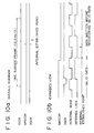
reference counter 29 would count N frames. - The reason why an offset of 64 frames is given to the read clock RFCK by the offset circuit 31 in a period of time from the rising of the reproduction synchronizing signal SCOR and the rising of the subcode synchronizing signal GRSCOR will be described below. Depending on the constitution of the
DSP circuit 10, the jitter frame margin extends over ±28 frames. In the following passage it is assumed that the reproduction subcode signal SCOR is used for reading the subcode Q in themicrocomputer 20 and the subcode synchronizing signal GRSCOR is used for performing sound linking within subcode frames. - When performing sound linking, the
microcomputer 20 accesses a position immediately preceding the occurrence of a track jump, compares data regarding the last valid address of the DRAM 23 (this data being present at the microcomputer 20) with the subcode Q being read from the disc 1, and determines a point for sound linking. That is, themicrocomputer 20 must determine whether to perform sound linking or not by reading the subcode Q at the rising of the reproduction subcode synchronizing signal SCOR and comparing the read subcode Q with the data regarding the last valid DRAM address. - Referring to Fig. 7, there is shown a timing chart obtained when the frame jitter margin is maximized (+28 frames) and minimized (-28 frames). In Fig. 7, a time between the rising of the reproduction subcode synchronizing signal SCOR and the rising of the subcode synchronizing signal GRSCOR is a minimum of 2.45 ms and a maximum of 6.23 ms. Namely, in sound linking, it is most critical for the
microcomputer 20 when the frame jitter margin is -28 frames. During this 2.45 ms, the microcomputer must read the subcode Q to compare it with the data relating to the last established address of theDRAM 23 to determine whether to perform sound linking or not. - Next, processing procedures for establishing (validating) data and linking sounds will be described. First, the data establishing procedure will be described with reference to a flowchart of Fig. 8. Upon detection of the rising of the reproduction subcode synchronizing signal SCOR (step S1), the
microcomputer 20 activates a built-in timer (step S2) and reads the subcode Q (step S3). - Then, the microcomputer compares a difference between the read subcode Q and the previously established address to determine whether a sound overleap has taken place or not (step S4). If the sound overleap has been detected, the
microcomputer 20 passes control to a sound linking routine to be described later. If no sound overleap has been detected, themicrocomputer 20 monitors the rising of the subcode synchronizing signal GRSCOR (step S5). Upon detection of the rising of the subcode synchronizing signal GRSCOR, themicrocomputer 20 determines, based on a time measured by the above-mentioned timer, whether the subcode synchronizing signal GRSCOR has come between 2.45 ms and 6.23 ms (step S6). - If the subcode synchronizing signal GRSCOR has not come between 2.45 ms and 6.23 ms, then the
microcomputer 20 passes control to the sound linking routine. If the GRSCOR has come during that period of time, then themicrocomputer 20 sends a registration permit signal XQOK to theESP controller 22 while the subcode synchronizing signal GRSCOR is HIGH (about 68 (µs) (step S7)). When the registration permit signal XQOK has come to theESP controller 22 while the subcode synchronizing signal GRSCOR is HIGH, theESP controller 22 loads the write address WA in the valid address VWA to establish the data. It should be noted here that a point to be established by the ESP controller is always fixed within one subcode frame as shown in Fig. 10. - Having sent the registration permit signal XQOK, the
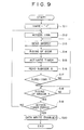
microcomputer 20 then sends a confirmation request signal XSOE to theESP controller 22 to confirm whether the registration has been made correctly (step S8). When the data has been registered correctly, theESP controller 22 returns a registration complete signal QRCVD of HIGH level in response to the XSOE signal. Themicrocomputer 20 waits for the return of the QRCVD signal from the ESP controller 22 (step S9). If the QRCVD is not HIGH, themicrocomputer 20 passes control to the sound linking routine. If the QRCVD is HIGH, themicrocomputer 20 updates the valid address VWA (step S10), thereby ending the series of processing operations for the data establishment. - Then, the sound linking processing will be described with reference to a flowchart of Fig. 9. A write enable signal, XWRE, when at a LOW level enables the writing of data to the
DRAM 23. First, themicrocomputer 20 makes HIGH the write enable signal XWRE, thereby disabling the writing (step S11). Then, themicrocomputer 20 accesses the final valid address VWA it holds (step S12) and sends a SCOR resynchronizing signal GRSRST to the ESP controller 22 (step S13). In theESP controller 22, thematch detector 33 of the subcode synchronizing signal generator (Fig. 4) is reset by the SCOR resynchronizing signal GRSRST. - Subsequently, upon detection of the rising of the reproduction subcode synchronizing signal SCOR (step S14), the
microcomputer 20 activates the incorporated timer (step S15) to read the subcode Q (step S16). Then, themicrocomputer 20 determines whether the subcode Q matches the final valid address VWA (step S17). If no match is found, the microcomputer returns to step S14 to repeat the above-mentioned processing operations. - If the subcode Q and the final valid address VWA are found matching, the
microcomputer 20 monitors the rising of the subcode synchronizing signal GRSCOR (step S18). Upon detection of the rising of the subcode synchronizing signal GRSCOR, themicrocomputer 20 determines, based on the time measured by the timer, whether the subcode synchronizing signal GRSCOR has come within a period of time between 2.45 ms and 6.23 ms (step S19). If the subcode synchronizing signal GRSCOR has not come within the period of time between 2.45 ms and 6.23 ms, the microcomputer returns to step S12 to repeat the above-mentioned processing operations. - On the other hand, if the GRSCOR signal has been found coming within the above-mentioned period of time, the
microcomputer 20 makes LOW the above-mentioned write enable signal XWRE while the subcode synchronizing signal GRSCOR is HIGH, thereby permitting the ESP controller to write the data to the DRAM 23 (step S20). This causes theESP controller 22 to start writing the PCM data read from the disc 1 to theDRAM 23 when the established point of the subcode frame has been reached as shown in Fig. 11. As a result, the continuity of the PCM data is ensured, thereby implementing sound linking. Fig. 12 shows a timing chart describing the series of operations ranging from the detection of sound overleap to the sound linking. - Meanwhile, the
ESP controller 22 incorporates a RAM 27 dedicated to the subcode Q as shown in Fig. 1. This RAM is provided to store the time information of reproduction data. However, because it is impractical to store in the RAM 27 all the time information corresponding to the PCM data stored in theexternal DRAM 23 in terms of storage capacity, the time information to be stored in the RAM 27 are thinned out to some extent in the present embodiment. In what follows, the thinning out will be described on the supposition that theexternal DRAM 23 has a storage capacity of 16M (i.e. 16 x 220) bits. - A symbol of 16 bits can be written to the
DRAM 23 one M (220) times. Because the symbol is written twice for each of the left and right channels on a sampling frequency fs (=44.1 kHz), PCM data equivalent to the following value can be stored in theDRAM 23 when it is full: - Until the
DRAM 23 is full, the following number of subcode frames come: - Now, it is supposed that all the time information corresponding to the data in the
external DRAM 23 are written to the RAM 27 in theESP controller 22, with the written time information being restricted to one byte of TNO (tempo number), one byte of IND (index), one byte of MIN (minute) and one byte of SEC (second) of the subcode Q per subcode frame. Then, a RAM having the following storage capacity is required, making the implementation of such a RAM impractical: - Consequently, in the present embodiment, the capacity of the RAM 27 to be incorporated in the
ESP controller 22 was set to several K bits. Two further points were considered; namely, the number of read times per second that does not hamper data display, and a time information thinning-out degree that does not make data display disagreeable to the eye. Ultimately, 20 write operations per second and 10 read operations per second were derived. - Thus, linking PCM data with its time information by making the upper address of the
external DRAM 23 common with the address of the incorporated RAM 27 allows themicrocomputer 20 to correct the subcode Q in time axis by means of two operations; sending the time information of the PCM data being read from the disc 1 to theESP controller 22 and reading the time information from theESP controller 22. Conventionally, themicrocomputer 20 performs the time information conversion while monitoring the storage capacity of theDRAM 23 for displaying resultant data, thereby increasing the load of themicrocomputer 20. - In the
ESP controller 22, the writing of the subcode Q to the incorporated RAM is performed while a write enable signal MWE is HIGH (13.3 ms/2) as shown in Fig. 13. In this case, the one-byte data TNO, IND, MIN, and SEC are put on serial I/F data, clock, and latch to be written in four time intervals with the least significant bit (LSB) first. On the other hand, the reading of the subcode Q from the RAM 27 is performed while the read enable signal MRE is HIGH (13.3 ms/2) as shown in Fig. 14. In this case, a LOW level pulse is sent 32 times as a read clock QRCK to read the TNO, IND, MIN, and SEC from a subcode Q output terminal QTBC with the LSB first. - In the above-mentioned embodiment, the present invention has been described as applied to a CD player. It will be apparent to those skilled in the art that the present invention is not restricted to the CD player; instead, the present invention is applicable to other type of disc players such as those for reproducing an MD or a CD-ROM disc.
- As mentioned above and according to the invention, an amount of jitter contained in a write clock synchronized with a reproduction clock as opposed to a read clock synchronized with a fixed clock is detected, the detected jitter amount is added to or subtracted from a count output obtained by counting the write clock for 98 frames and an offset for the predetermined number of frames is given to an addition/subtraction result to generate a subcode synchronizing signal completely synchronized with the read clock, based on which subcode synchronizing signal reproduction data is written to a large-capacity memory. This constitution implements data establishment on the time axis and sound linking on the time axis, so that, if the reproduction data at a sound linking point is processed with previous-value hold or interpolation, the sound linking can be performed without error and, in software having successive fixed patterns, correct sound linking is assured.
- According to the invention, a reproduction subcode synchronizing signal read from a disc is compared with a count output of a write clock and, only when a match is found by the predetermined number of times successively, a generated subcode synchronized signal is made valid. This constitution eliminates a false reproduction subcode synchronizing signal caused by a scratch or the like on the disc and determines a true reproduction subcode synchronizing signal, thereby enabling to generate the subcode synchronizing signal without being affected by the scratch or the like on the disc.
- According to the invention, time information of reproduction data to be written to a large-capacity memory is stored in a memory for storing the time information. In this constitution, the stored time information makes it unnecessary to perform a time converting operation while monitoring the storage capacity of the large-capacity memory, thereby mitigating the load placed on microcomputer software and permitting the display of the time information in real-time.
- According to the invention, the time information is stored in the memory for storing the time information in a thinned-out manner to restrict a capacity of this memory to a minimum, thereby providing the time information of reproduction data at a relatively low cost.
- According to the invention, a subcode synchronizing signal synchronized with a read clock is generated. Therefore, if no sound overleap has occurred, the generated subcode synchronizing signal is used to establish reproduction data to be stored in the large-scale memory, thereby permitting data establishment by time axis. Further, according to the invention, if a sound overleap has occurred, writing of the reproduction data to the large-capacity memory is started on the basis of the generated subcode synchronizing signal, thereby implementing sound linking on the time axis. Consequently, even if the reproduction data at a sound linking point is processed with previous-value hold or interpolation, the sound linking can be performed without involving an error and, in software having fixed patterns successively, sounds can be linked correctly.
- While the invention has been particularly shown and described with reference to preferred embodiments thereof, it will be understood by those skilled in the art that the foregoing and other changes in form and details can be made therein without departing from the spirit and scope of the invention.
Claims (7)
- A disc player constituted to write reproduction data from a disc (1) to a large-capacity memory (23) and then read said reproduction data from said large-capacity memory (23) for output, comprising subcode signal processing means (13), characterized in that said subcode signal processing means (13) comprises:wherein there is further provided in the disc player means for detecting a sound overleap by reading, in synchronization with a reproduction subcode synchronizing signal (SCOR) obtained from said reproduction data, time information of a subcode (SUBQ) contained in said reproduction data, and by using said time information and a finally established address (VWA) of said large capacity memory (23);jitter detecting means (28) for detecting an amount of jitter contained in a second clock (WFCK) synchronized with said reproduction data as opposed to a first clock (RFCK) of a fixed frequency;counting means (29) for counting said second clock (WFCK) for 98 frames;algebraically adding means (30) for algebraically adding said amount of jitter to a count output of said counting means (29);offset means (31) for giving a time offset of a predetermined number of frames to an output of said algebraically adding means (30);match detecting means (33) for detecting a match by a predetermined number of times successively between a reproduction subcode synchronizing signal (SCOR) obtained from said reproduction data and said count output of said counting means (29); andoutput determining means (32) for making valid said output of said offset means (31) only when said match detecting means (33) has found said match;
wherein said time offset is adapted to compensate for time spent detecting a sound overleap, the duration of said time offset being such that the total of the maximum jitter margin and the time offset is less than one subcode frame; and
wherein writing of said reproduction data to said large-capacity memory (23) is conditional upon the timing of pulses in the output of said offset means (31). - A disc player according to claim 1, characterized in that it comprises :wherein said subcode signal processing means (13) captures the signal coming from said eight-to-fourteen modulation demodulating means (12) to output a subcode signal; andan eight-to-fourteen modulation demodulating means (12) for demodulating a radio frequency signal and the like coming from an optical pick-up device (3);first storage means (14) for storing a signal coming from said eight-to-fourteen modulation demodulating means (12);error correcting means (15) for correcting an error of said signal stored in said first storage means (14) and outputting the corrected signal to said first storage means (14);deinterleaving means (16) for deinterleaving said signal coming from said first storage means (14);spindle servo signal processing means (18) for controlling a spindle-drive motor (2) in accordance with a signal coming from said deinterleaving means (16);a microcomputer (20); andan electric shock-proof controller (22) for capturing the signal coming from said deinterleaving means (16) to detect for signal drop, said electric shock-proof controller (22) being connected to second storage means (23) and said microcomputer (20),
said microcomputer (20) checks said subcode signal coming from said subcode signal processing means (13) for signal drop. - A disc player as defined in claim 1 or 2, characterized in that it further comprises :
a memory (27) for storing time information of said reproduction data to be written to said second storage means (23). - A disc player as defined in claim 3, wherein said time information is stored in said second storage means (23) in a thinned-out manner.
- A reproduction data processing method for a disc player constituted to write reproduction data from a disc (1) to a large capacity memory (23) and then read said reproduction data from said large capacity memory (23) for output, characterized in that the method comprises the steps of:wherein said time offset is adapted to compensate for time spent detecting a sound overleap, the duration of said time offset being such that the total of the maximum jitter margin and the time offset is less than one subcode frame; and(a) detecting an amount of jitter contained in a second clock (WFCK) synchronized with said reproduction data as opposed to a first clock (RFCK) of a fixed frequency;(b) counting said second clock (WFCK) for 98 frames;(c) algebraically adding said amount of jitter to a count output of step (b) ;(d) giving a time offset of a predetermined number of frames to an output of step (c);(e) detecting a match by a predetermined number of times successively between a reproduction subcode synchronizing signal (SCOR) obtained from said reproduction data and said count output of step (b);(f) making valid said output of step (d) only when said match has been detected in step (e); and(g) detecting a sound overleap by reading time information of a subcode (SUBQ) contained in said reproduction data, in synchronization with a reproduction subcode synchronizing signal (SCOR) obtained from said reproduction data and by using said time information and a finally established address (VWA) of said large capacity memory (23);
wherein writing of said reproduction data to said large-capacity memory (23) is conditional upon the timing of pulses in the output of step (d) - A reproduction data processing method as defined in claim 5, characterized in that it comprises the steps of:generating a subcode synchronizing signal (GSRCOR) synchronized with a clock (RFCK) having a fixed frequency; andif no sound overleap has been detected, reproduction data is established to be stored in said large capacity memory (23) based on said subcode synchronizing signal (GRSCOR).
- A reproduction data processing method as defined in claim 6, characterized in that it further comprises the steps of:accessing said finally established address (VWA) upon detection of a sound overleap;comparing said finally established address (VWA) with said time information of said subcode (SUBQ) read in synchronization with said reproduction subcode synchronizing signal (SCOR); andif a match is found between, said subcode (SUBQ) and said finally established address (VWA), starting to write said reproduction data to said large capacity memory (23) based on said subcode synchronizing signal (GRSCOR).
Applications Claiming Priority (3)
| Application Number | Priority Date | Filing Date | Title |
|---|---|---|---|
| JP346575/93 | 1993-12-22 | ||
| JP34657593A JP3321950B2 (en) | 1993-12-22 | 1993-12-22 | Disc player and method for processing reproduced data |
| JP34657593 | 1993-12-22 |
Publications (3)
| Publication Number | Publication Date |
|---|---|
| EP0660322A2 EP0660322A2 (en) | 1995-06-28 |
| EP0660322A3 EP0660322A3 (en) | 1996-12-04 |
| EP0660322B1 true EP0660322B1 (en) | 2003-03-26 |
Family
ID=18384354
Family Applications (1)
| Application Number | Title | Priority Date | Filing Date |
|---|---|---|---|
| EP94402987A Expired - Lifetime EP0660322B1 (en) | 1993-12-22 | 1994-12-22 | Optical disc player and processing method for reproduction data of the optical disc player |
Country Status (6)
| Country | Link |
|---|---|
| US (1) | US5508983A (en) |
| EP (1) | EP0660322B1 (en) |
| JP (1) | JP3321950B2 (en) |
| KR (1) | KR100284447B1 (en) |
| CN (1) | CN1096059C (en) |
| DE (1) | DE69432343T2 (en) |
Families Citing this family (22)
| Publication number | Priority date | Publication date | Assignee | Title |
|---|---|---|---|---|
| US5818801A (en) * | 1995-06-30 | 1998-10-06 | Sanyo Electric Co., Ltd. | Shockproof optical reproduction device |
| KR0180307B1 (en) * | 1995-10-06 | 1999-04-15 | 김광호 | Servo circuit |
| US6058453A (en) * | 1997-08-18 | 2000-05-02 | Stmicroelectronics, Inc. | Method and apparatus for subcode/data synchronization in a compact disc system |
| US6229769B1 (en) * | 1997-08-18 | 2001-05-08 | Stmicroelectronics N.V. | Methods and apparatus for delayed block release in compact disc systems |
| US6131138A (en) * | 1997-08-18 | 2000-10-10 | Stmicroelectronics N.V. | Variable speed compact disc drive including an elastic buffer |
| US6064634A (en) * | 1997-08-18 | 2000-05-16 | Stmicroelectronics, N.V. | Compact disc player capable of automatically generating a start command |
| TW359811B (en) * | 1997-09-23 | 1999-06-01 | Mediatek Inc | CD playback system with synchronous and anti-vibration functions |
| NL1007870C2 (en) * | 1997-12-23 | 1999-06-30 | United Microelectronics Corp | Compact disk player with vibration immune uninterrupted playback |
| US6442329B1 (en) * | 1998-02-28 | 2002-08-27 | Michael L. Gough | Method and apparatus for traversing a multiplexed data packet stream |
| US6393430B1 (en) | 1998-05-08 | 2002-05-21 | Sony Corporation | Method and system for automatically recording music data files by using the hard drive of a personal computer as an intermediate storage medium |
| JP3862875B2 (en) * | 1998-10-29 | 2006-12-27 | パイオニア株式会社 | Disc player |
| JP2000165791A (en) * | 1998-11-25 | 2000-06-16 | Canon Inc | Reproducing device |
| JP4284834B2 (en) * | 1999-06-23 | 2009-06-24 | ソニー株式会社 | Reproduction method and reproduction apparatus |
| US6591392B1 (en) | 1999-11-24 | 2003-07-08 | Oak Technology, Inc. | Compact disc subcode packing and error correction detection |
| JP2002015506A (en) * | 2000-06-30 | 2002-01-18 | Sanyo Electric Co Ltd | Signal-processing circuit |
| US7042813B2 (en) * | 2002-05-13 | 2006-05-09 | Texas Instruments Incorporated | Shock protection for compressed audio on a CD player |
| US7170249B2 (en) * | 2003-06-06 | 2007-01-30 | Seagate Technology Llc | Electrical phase compensation in BEMF spindle motor control |
| US20040245950A1 (en) * | 2003-06-06 | 2004-12-09 | Ang June Christian | Electrical phase compensation in BEMF spindle motor control |
| JP2005122787A (en) * | 2003-10-15 | 2005-05-12 | Casio Comput Co Ltd | Data reproducing device and program for data reproduction processing |
| KR100524992B1 (en) | 2003-11-11 | 2005-10-31 | 삼성전자주식회사 | Disk player for allotting pointers to CD frames and storing pointers and frames to memory and method for controlling reproducing data of disk player |
| CN100378861C (en) * | 2004-05-21 | 2008-04-02 | 扬智科技股份有限公司 | DVD non-juncture playback system containing two timers |
| US7630998B2 (en) * | 2005-06-10 | 2009-12-08 | Microsoft Corporation | Performing a deletion of a node in a tree data storage structure |
Family Cites Families (11)
| Publication number | Priority date | Publication date | Assignee | Title |
|---|---|---|---|---|
| DE3619258A1 (en) * | 1986-06-07 | 1987-12-10 | Blaupunkt Werke Gmbh | COMPACT DISC (CD) PLAYER |
| KR910005644B1 (en) * | 1986-09-19 | 1991-08-01 | 가부시키가이샤 도시바 | Disk recording/reproducing apparatus |
| JPH033165A (en) * | 1989-05-31 | 1991-01-09 | Sony Corp | Optical disk reproducing device |
| JP2881980B2 (en) * | 1990-06-29 | 1999-04-12 | ソニー株式会社 | Disk recording device and disk reproducing device |
| JP2995822B2 (en) * | 1990-08-23 | 1999-12-27 | ソニー株式会社 | Recording device and reproducing device for disk-shaped recording medium |
| JP3084916B2 (en) * | 1992-03-31 | 2000-09-04 | ソニー株式会社 | Playback data processing circuit for disc player |
| JP3318841B2 (en) * | 1992-08-20 | 2002-08-26 | ソニー株式会社 | Reproduction device and reproduction method |
| US5412628A (en) * | 1992-10-05 | 1995-05-02 | Yamaha Corporation | Apparatus for intermittently recording and reproducing a signal on a disc type recording medium |
| US5418762A (en) * | 1992-12-09 | 1995-05-23 | Sony Corporation | Optical disk recording device having a pre-recording mode |
| JP2902240B2 (en) * | 1992-12-28 | 1999-06-07 | アルパイン株式会社 | Disc playing method |
| EP0607861B1 (en) * | 1993-01-21 | 2000-04-05 | Hitachi, Ltd. | Disk reproducing apparatus |
-
1993
- 1993-12-22 JP JP34657593A patent/JP3321950B2/en not_active Expired - Fee Related
-
1994
- 1994-12-01 US US08/352,793 patent/US5508983A/en not_active Expired - Lifetime
- 1994-12-09 KR KR1019940033543A patent/KR100284447B1/en not_active IP Right Cessation
- 1994-12-22 DE DE69432343T patent/DE69432343T2/en not_active Expired - Lifetime
- 1994-12-22 EP EP94402987A patent/EP0660322B1/en not_active Expired - Lifetime
- 1994-12-22 CN CN94119298A patent/CN1096059C/en not_active Expired - Fee Related
Also Published As
| Publication number | Publication date |
|---|---|
| JP3321950B2 (en) | 2002-09-09 |
| CN1114449A (en) | 1996-01-03 |
| DE69432343D1 (en) | 2003-04-30 |
| CN1096059C (en) | 2002-12-11 |
| KR950020651A (en) | 1995-07-24 |
| DE69432343T2 (en) | 2004-03-04 |
| JPH07182790A (en) | 1995-07-21 |
| EP0660322A2 (en) | 1995-06-28 |
| KR100284447B1 (en) | 2001-04-02 |
| US5508983A (en) | 1996-04-16 |
| EP0660322A3 (en) | 1996-12-04 |
Similar Documents
| Publication | Publication Date | Title |
|---|---|---|
| EP0660322B1 (en) | Optical disc player and processing method for reproduction data of the optical disc player | |
| US4860272A (en) | Erroneous track jump restoration apparatus for optical record disc player | |
| US4603412A (en) | Disc rotation servo control apparatus in a disc player | |
| EP0974966B1 (en) | Disk recording system | |
| US4672597A (en) | Clock signal reproducing circuit for a player reproducing information of a disc | |
| EP0553851B1 (en) | A data reproducing apparatus | |
| JP2849006B2 (en) | Information playback device | |
| US5615194A (en) | Disk reproducing apparatus and method for reproducing an audio signal and a subcode at N times normal speed from a disk | |
| US6246650B1 (en) | Method and apparatus for high speed data reproduction | |
| KR100358606B1 (en) | Disc recorder | |
| JP2000293942A (en) | Optical disk reproducing device | |
| JP4768982B2 (en) | Disc player for allocating a pointer for each frame of CD data and storing it in a memory, and reproduction data processing method for disc player | |
| JP2653278B2 (en) | Disc recording and playback device | |
| JPH11242859A (en) | Address interpolating method and address interpolating device | |
| JP3146877B2 (en) | Decoder and playback device | |
| JPH10149629A (en) | Disk reproducing device | |
| JP2640059B2 (en) | Disc player | |
| KR960003704B1 (en) | High driving apparatus and method for disk player | |
| JP2579083B2 (en) | Disk recording device and disk reproducing device | |
| JPH077568B2 (en) | Information playback device | |
| JPH0721694A (en) | Information recording and reproducing device | |
| JP2003178478A (en) | Data reproducing apparatus | |
| JPH10149628A (en) | Disk reproducing device | |
| JPH0746482B2 (en) | Playback device | |
| JPH07192286A (en) | Optical disk recording and reproducing device |
Legal Events
| Date | Code | Title | Description |
|---|---|---|---|
| PUAI | Public reference made under article 153(3) epc to a published international application that has entered the european phase |
Free format text: ORIGINAL CODE: 0009012 |
|
| AK | Designated contracting states |
Kind code of ref document: A2 Designated state(s): DE FR GB |
|
| PUAL | Search report despatched |
Free format text: ORIGINAL CODE: 0009013 |
|
| AK | Designated contracting states |
Kind code of ref document: A3 Designated state(s): DE FR GB |
|
| 17P | Request for examination filed |
Effective date: 19970521 |
|
| 17Q | First examination report despatched |
Effective date: 19970624 |
|
| GRAG | Despatch of communication of intention to grant |
Free format text: ORIGINAL CODE: EPIDOS AGRA |
|
| GRAG | Despatch of communication of intention to grant |
Free format text: ORIGINAL CODE: EPIDOS AGRA |
|
| GRAG | Despatch of communication of intention to grant |
Free format text: ORIGINAL CODE: EPIDOS AGRA |
|
| GRAH | Despatch of communication of intention to grant a patent |
Free format text: ORIGINAL CODE: EPIDOS IGRA |
|
| GRAH | Despatch of communication of intention to grant a patent |
Free format text: ORIGINAL CODE: EPIDOS IGRA |
|
| GRAA | (expected) grant |
Free format text: ORIGINAL CODE: 0009210 |
|
| AK | Designated contracting states |
Designated state(s): DE FR GB |
|
| REG | Reference to a national code |
Ref country code: GB Ref legal event code: FG4D |
|
| REF | Corresponds to: |
Ref document number: 69432343 Country of ref document: DE Date of ref document: 20030430 Kind code of ref document: P |
|
| ET | Fr: translation filed | ||
| PLBE | No opposition filed within time limit |
Free format text: ORIGINAL CODE: 0009261 |
|
| STAA | Information on the status of an ep patent application or granted ep patent |
Free format text: STATUS: NO OPPOSITION FILED WITHIN TIME LIMIT |
|
| 26N | No opposition filed |
Effective date: 20031230 |
|
| REG | Reference to a national code |
Ref country code: GB Ref legal event code: 746 Effective date: 20120703 |
|
| REG | Reference to a national code |
Ref country code: DE Ref legal event code: R084 Ref document number: 69432343 Country of ref document: DE Effective date: 20120614 |
|
| PGFP | Annual fee paid to national office [announced via postgrant information from national office to epo] |
Ref country code: GB Payment date: 20121220 Year of fee payment: 19 |
|
| PGFP | Annual fee paid to national office [announced via postgrant information from national office to epo] |
Ref country code: FR Payment date: 20130130 Year of fee payment: 19 Ref country code: DE Payment date: 20121220 Year of fee payment: 19 |
|
| REG | Reference to a national code |
Ref country code: DE Ref legal event code: R119 Ref document number: 69432343 Country of ref document: DE |
|
| GBPC | Gb: european patent ceased through non-payment of renewal fee |
Effective date: 20131222 |
|
| REG | Reference to a national code |
Ref country code: FR Ref legal event code: ST Effective date: 20140829 |
|
| REG | Reference to a national code |
Ref country code: DE Ref legal event code: R119 Ref document number: 69432343 Country of ref document: DE Effective date: 20140701 |
|
| PG25 | Lapsed in a contracting state [announced via postgrant information from national office to epo] |
Ref country code: DE Free format text: LAPSE BECAUSE OF NON-PAYMENT OF DUE FEES Effective date: 20140701 |
|
| PG25 | Lapsed in a contracting state [announced via postgrant information from national office to epo] |
Ref country code: FR Free format text: LAPSE BECAUSE OF NON-PAYMENT OF DUE FEES Effective date: 20131231 Ref country code: GB Free format text: LAPSE BECAUSE OF NON-PAYMENT OF DUE FEES Effective date: 20131222 |