EP0660281A1 - Radio communication device combinable with a radio modem for computer - Google Patents
Radio communication device combinable with a radio modem for computer Download PDFInfo
- Publication number
- EP0660281A1 EP0660281A1 EP94120575A EP94120575A EP0660281A1 EP 0660281 A1 EP0660281 A1 EP 0660281A1 EP 94120575 A EP94120575 A EP 94120575A EP 94120575 A EP94120575 A EP 94120575A EP 0660281 A1 EP0660281 A1 EP 0660281A1
- Authority
- EP
- European Patent Office
- Prior art keywords
- radio
- modem
- signal
- message
- communication device
- Prior art date
- Legal status (The legal status is an assumption and is not a legal conclusion. Google has not performed a legal analysis and makes no representation as to the accuracy of the status listed.)
- Withdrawn
Links
Images


Classifications
-
- G—PHYSICS
- G08—SIGNALLING
- G08B—SIGNALLING OR CALLING SYSTEMS; ORDER TELEGRAPHS; ALARM SYSTEMS
- G08B5/00—Visible signalling systems, e.g. personal calling systems, remote indication of seats occupied
- G08B5/22—Visible signalling systems, e.g. personal calling systems, remote indication of seats occupied using electric transmission; using electromagnetic transmission
- G08B5/222—Personal calling arrangements or devices, i.e. paging systems
- G08B5/223—Personal calling arrangements or devices, i.e. paging systems using wireless transmission
- G08B5/224—Paging receivers with visible signalling details
- G08B5/228—Paging receivers with visible signalling details combined with other devices having a different main function, e.g. watches
Definitions
- the present invention relates to a radio communication device, and more particularly, to a radio communication device combinable with a radio modem for a computer.
- the communication to a computer utilizing a paging system is performed by letting the computer receive radio selective calling signals through a small-sized radio modem connected to the computer.
- the computer takes in the radio selective calling signals with an identification (ID) number which coincides with an ID number assigned to the modem.
- ID an identification
- the modem receives the radio selective calling signals and stores messages included in the received signals into a built-in memory.
- the modem informs the user of receiving the selective calling signals.
- Such system having a modem with a computer is disclosed in, for example, Japan Laid-Open Patent Application No. 262069/1991 (JP-A-03-262069).
- the modem does not have a display unit
- the user cannot confirm the received message when the MODEM is separated from the computer and the selective calling signal is received.
- the user must wait until the modem is connected to the computer to see the received message.
- the modem does not have a message deletion function in addition to lack of the display unit, messages are not stored in the built-in memory of the modem after the memory capacity has been exhausted. Consequently, the user cannot confirm the receipt of some messages.
- connection terminals of the modem have a shape and size, such as in Model No. PCMCIA II, uniquely adaptable for connection to the computer.
- Another object of the present invention is to provide a radio communication device combinable with a radio modem for a computer capable of displaying a received message when a user carries the radio modem.
- a radio modem for a computer includes a first connection part electrically connected to the computer.
- a case includes a second connection part electrically connected to the first connection part of the radio modem.
- the radio modem and the case is operated as a radio communication device when the radio modem and the case are connected electrically.
- the case includes an operating portion, a display for displaying a received message, and a controller for controlling the radio modem based on an operation of the operating portion and for supplying a signal from the radio modem to the display via the first and second connection parts.
- the radio modem includes a radio section for receiving a radio signal, a decoder for decoding the radio signal to a decoded signal, a first memory for storing an assigned calling number, a second memory for storing the received message included in the decoded signal, and a CPU for comparing a received calling number included in the decoded signal with the assigned calling number and for communicating with the controller in the case via the first and second connection parts.
- the case includes deleting means for deleting the received message in the second memory in response to the operation of the operating portion.
- FIG. 1 is a block diagram of a preferred embodiment according to the present invention.
- a selective calling receiver consists of a radio modem 10 and a carrying case 30 to which the modem 10 is inserted.
- the modem 10 and the carrying case 30 are connected by means of connection parts 50a and 50b, such as PCMCIA II connection terminals.
- the radio modem 10 is equipped with an antenna 12, a radio section 14, a decoder 16, a calling number memory 18, a message memory 20, a CPU 22, an interface for PCMCIA 24, and the connection part 50a.
- the carrying case 30 is equipped with a battery 28, an operating portion 32, a-controller 34, a display 36, an informing portion 42, and the connection part 50b.
- the display 36 includes an LCD driver 38 and an LCD 40.
- the informing portion 42 includes a speaker 44, an LED 46, and a vibrator 48.
- the battery 28 supplies a power voltage to each of the circuits.
- FIG. 2(a) is an external view of the radio modem 10 and the carrying case 30 shown in FIG. 1, and FIG. 2(b) is an external view where the modem 10 is inserted into the carrying case 30.
- the selective calling receiver of the type combinable with a radio modem for computer of the preferred embodiment according to the present invention is formed in the shape of a box.
- the radio modem 10 has a handle 26 to inserting or pulling the radio modem 10 to or from the carrying case 30.
- the carrying case 30 includes switches 52, 54 and 56 which constitute the operating portion 32 as shown in FIG. 1.
- a set switch 52 is used, for example, for stopping an informing operation, a display start, or executing a message deletion.
- a mode switch 54 is used, for example, for selecting modes.
- a select switch 56 is used, for example, for message selection.
- FIGs. 3(a) and 3(b) illustrate external views, respectively, of a first connection part 50a of the radio modem 10 and a second connection part 50b of the carrying case 30.
- the first connection part 50a is constituted by a plurality of socket connectors and the second connection part 50b is constituted by a plurality of pin connectors to which the socket connectors are inserted.
- Connectors Ds are for receiving and sending messages and connectors As are for detecting a switch operation.
- Connectors CD1 and CD2 are used for detecting a connection between the radio modem 10 and the carrying case 30.
- Connectors VCC are used for a power supply from the battery 28.
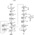
- FIG. 4 is a flow-chart illustrating the receiving and informing operation according to the present invention.
- Step S101 in FIG. 4 When the radio modem 10 is inserted into the carrying case 30 (Step S101 in FIG. 4), it is detected whether or not the socket connectors of the modem 10 is connected to the pin connectors of the case 30 using the connectors CD1 and CD2 (Step S102). If it is detected that the modem 10 are connected to the case 30, the selective calling receiver moves into a receiving mode (Step S103). If it is not detected, it waits for the modem insertion by a user again.
- the radio signal received by the antenna 12 in the radio modem 10 for a computer is demodulated in the radio section 14, and the demodulated signal is waveform-shaped and converted to a digital signal (Step S105).
- the decoder 16 compares an assigned calling number in the calling number memory 18 with a received calling number included in the digital signal (Step S106), and sends a detection signal to the CPU 22 when both of the calling number coincide (Step S107).
- the CPU 22 may be a model TEC 1000 made by Texas Instruments. If the assigned calling number does not coincide with the received calling number, the selective calling receiver returns to the receiving mode.
- the decoder 16 After sending the detection signal, the decoder 16 sends a received message signal to the message memory 20 (Step S108) and the PCMCIA interface 24. In response, the PCMCIA interface 24 sends the received message signal to the controller 34 in the carrying case 30 via the connection parts 50a and 50b (Step S109).
- the connectors Ds of the connection parts 50a and 50b are used for the received message signal.
- the controller 34 informs the user of a signal reception by driving one of the informing portion 38 (Step S110) and drives the LCD driver 40 to display the received message on the LCD 42 (Step S111). If the set switch 52 (FIG. 2) in the operating portion 32 is depressed by the user (Step S112), the controller 34 stops displaying the received message and informing the user of the signal reception (Step S113). If the set switch 52 is not depressed, the received message display and informing operation is continued.
- FIG. 5 is a flow-chart illustrating the operations of displaying the stored messages and of deleting an unwanted message.
- Step S201 in FIG. 5 When the set switch 52 (FIG. 2) is depressed (Step S201 in FIG. 5), it becomes a display mode (Step S202) and a message display instruction signal is sent to the CPU 22 from the controller 34 via connectors As of the connection parts 50a and 50b and the interface 24 (Step S203). In response, the CPU 22 causes a first stored message in the message memory 20 to send to the controller 34 via the interface 25 and connectors Ds of the connection parts 50a and 50b and to display the first message on the display 36 (Step S204).
- Step S205 If the displayed first message is not a desired message for the user, i.e., the select switch 56 is depressed (Step S205), a message select signal is sent from the controller 34 to the CPU 22 via the connectors As and the interface 24 (Step S206). In response, the CPU 22 causes the next message signal to send the controller 34 similar to the first message signal and to display the second message on the display 36 (Step S207). These steps S205 to S207 are repeated until the desired message is displayed.
- Step S208 the controller 34 sends a display stop signal to the CPU 22 via the connectors As and the interface 24 and the message display operation is stopped (Step S209).
- Step S210 When the set switch is not depressed in Step S208, it is detected whether the mode switch 54 is depressed or not (Step S210). If the mode switch 54 is depressed (Step S210), i.e, the displayed message is an unwanted message, the display mode is changed to the message deletion mode (Step S211). If the mode switch 54 is not depressed, the step returns to Step S208.
- the message deletion mode when the set switch 52 is depressed (Step S212), the controller 34 sends a message deletion signal to the CPU 22 via the connectors As and the interface 24 (Step S213). In response, the CPU 20 deletes the displayed message from the message memory 20 (Step S214).
- Step S209 After the displayed message is deleted, a deletion finish signal is sent from a memory in the controller 34 to the display 36, and a message indicating the deletion finish is displayed on the display 36 (Step S215). If the set switch 52 is depressed after the message deletion (Step S216), the step follows Step S209.
- Step 212 if the set switch 52 is not depressed, it is detected whether or not a predetermined time t elapsed (Step S217).
- the predetermined time t elapsed from entering the deletion mode the step follows Step S209.
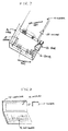
- FIGs. 6(a) and 6(b) illustrate external views of an another preferred embodiment according to the present invention.
- a shape of a carrying case 70 is different from that of the carrying case 30 shown in FIG. 2.
- the carrying case 70 has a folding mechanism by means of a hinge 60.
- FIG. 6(a) illustrates an external view of condition in which the carrying case 70 is closed and
- FIG. 6(b) illustrates an external view of condition in which the carrying case 70 is opened.
- FIG. 7 illustrates a mechanism of fixing a radio modem to a carrying case.
- the radio modem 10 has a hollow 62 on one side of the radio modem 10.
- the hollow 62 of the radio modem 10 is fixed to a hook 64 of the carrying case 70.
- the hook 64 of the carrying case 70 is provided at a position of fixing with the hollow 62 of the radio modem 10.
- the radio modem 10 is removed from the carrying case 70, the hook 64 is disconnected from the hollow 62 and the radio modem 10 is pushed by a power of springs 66 and 68 of the carrying case 70.
- the springs 66 and 68 are set on a face of pin connectors on the carrying case 70.
- FIG. 8 illustrates a computer and a radio modem thereof.
- a computer 72 has a display 74 and a key board 76.
- a radio modem 10 is inserted in the computer 72.
- connection parts 50a and 50b may be selected freely for communication between the radio modem and the carrying case.
- a radio modem for a computer is installed in a carrying case including a display, it is possible for a user to use the radio modem as a selective calling receiver and to confirm a received message when a user carries the radio modem.
Abstract
A radio modem for a computer receives a calling signal and stores a message included in the calling signal. A case is connected to the radio modem electrically through connection parts. The case is supplied the message from the radio modem via the connection parts and displays the message on the display.
Description
- The present invention relates to a radio communication device, and more particularly, to a radio communication device combinable with a radio modem for a computer.
- The communication to a computer utilizing a paging system is performed by letting the computer receive radio selective calling signals through a small-sized radio modem connected to the computer. The computer takes in the radio selective calling signals with an identification (ID) number which coincides with an ID number assigned to the modem. When a user carries the modem without the computer, the modem receives the radio selective calling signals and stores messages included in the received signals into a built-in memory. In addition, the modem informs the user of receiving the selective calling signals. Such system having a modem with a computer is disclosed in, for example, Japan Laid-Open Patent Application No. 262069/1991 (JP-A-03-262069).
- However, since the modem does not have a display unit, the user cannot confirm the received message when the MODEM is separated from the computer and the selective calling signal is received. As a result, the user must wait until the modem is connected to the computer to see the received message. Moreover, since the modem does not have a message deletion function in addition to lack of the display unit, messages are not stored in the built-in memory of the modem after the memory capacity has been exhausted. Consequently, the user cannot confirm the receipt of some messages.
- Furthermore, the modem has poor portability and insufficient strength due to the fact that connection terminals of the modem have a shape and size, such as in Model No. PCMCIA II, uniquely adaptable for connection to the computer.
- It is therefore an object of the present invention to provide a carrying case combinable with a radio modem for a computer.
- Another object of the present invention is to provide a radio communication device combinable with a radio modem for a computer capable of displaying a received message when a user carries the radio modem.
- It is further object of the present invention to provide a radio communication device combinable with a radio modem for a computer capable of deleting an unwanted massage.
- It is still further object of the present invention to provide a carrying case in which portability of radio modem for a computer is superior.
- According to the present invention, a radio modem for a computer includes a first connection part electrically connected to the computer. A case includes a second connection part electrically connected to the first connection part of the radio modem. The radio modem and the case is operated as a radio communication device when the radio modem and the case are connected electrically. In addition, the case includes an operating portion, a display for displaying a received message, and a controller for controlling the radio modem based on an operation of the operating portion and for supplying a signal from the radio modem to the display via the first and second connection parts.
- The radio modem includes a radio section for receiving a radio signal, a decoder for decoding the radio signal to a decoded signal, a first memory for storing an assigned calling number, a second memory for storing the received message included in the decoded signal, and a CPU for comparing a received calling number included in the decoded signal with the assigned calling number and for communicating with the controller in the case via the first and second connection parts. Moreover, the case includes deleting means for deleting the received message in the second memory in response to the operation of the operating portion.
- The above and other objects, features and advantages of this invention will become more apparent from the following detailed description taken with the accompanying drawings in which:
- FIG. 1 is a block diagram of a preferred embodiment according to the present invention;
- FIGs. 2(a) and 2(b) illustrate external views of a selective calling receiver of the preferred embodiment shown in FIG. 1;
- FIGS. 3(a) and 3(b) illustrate external views of the connection parts shown in FIG. 1;
- FIG. 4 is a flow-chart illustrating the receiving and informing operation according to the present invention;
- FIG. 5 is a flow-chart illustrating the operations of displaying the stored messages and of deleting an unwanted message according to the present invention;
- FIGs. 6(a) and 6(b) illustrate external views of an another preferred embodiment according to the present invention; and
- FIG. 7 illustrates a mechanism of fixing a radio modem to the carrying case shown in FIGs. 6(a) and 6(b); and
- FIG. 8 illustrates a computer and a radio modem inserted into the computer.
- In the drawings, the same reference numerals denote the same structural elements.
- FIG. 1 is a block diagram of a preferred embodiment according to the present invention. In FIG. 1, a selective calling receiver consists of a
radio modem 10 and acarrying case 30 to which themodem 10 is inserted. Themodem 10 and thecarrying case 30 are connected by means ofconnection parts 50a and 50b, such as PCMCIA II connection terminals. - The
radio modem 10 is equipped with an antenna 12, aradio section 14, adecoder 16, a calling number memory 18, amessage memory 20, aCPU 22, an interface for PCMCIA 24, and theconnection part 50a. Thecarrying case 30 is equipped with abattery 28, anoperating portion 32, a-controller 34, adisplay 36, aninforming portion 42, and the connection part 50b. Thedisplay 36 includes an LCD driver 38 and anLCD 40. Theinforming portion 42 includes a speaker 44, an LED 46, and a vibrator 48. Thebattery 28 supplies a power voltage to each of the circuits. - FIG. 2(a) is an external view of the
radio modem 10 and thecarrying case 30 shown in FIG. 1, and FIG. 2(b) is an external view where themodem 10 is inserted into thecarrying case 30. As shown in FIGs. 2(a) and 2(b), the selective calling receiver of the type combinable with a radio modem for computer of the preferred embodiment according to the present invention is formed in the shape of a box. In addition, theradio modem 10 has ahandle 26 to inserting or pulling theradio modem 10 to or from thecarrying case 30. - In FIG. 2, the
carrying case 30 includesswitches operating portion 32 as shown in FIG. 1. Aset switch 52 is used, for example, for stopping an informing operation, a display start, or executing a message deletion. Amode switch 54 is used, for example, for selecting modes. Aselect switch 56 is used, for example, for message selection. - FIGs. 3(a) and 3(b) illustrate external views, respectively, of a
first connection part 50a of theradio modem 10 and a second connection part 50b of thecarrying case 30. Thefirst connection part 50a is constituted by a plurality of socket connectors and the second connection part 50b is constituted by a plurality of pin connectors to which the socket connectors are inserted. - For example, as prescribed for PCMCIA connectors, thirty-four (34) socket connectors are lined up in two files and, similarly, thirty-four (34) pin connectors are lined up in two files. Functions of each pin are shown in the following table 1.


- Connectors Ds are for receiving and sending messages and connectors As are for detecting a switch operation. Connectors CD1 and CD2 are used for detecting a connection between the
radio modem 10 and thecarrying case 30. Connectors VCC are used for a power supply from thebattery 28. - Next, a receiving and informing operation will be described with reference to FIGs. 1 to 4. FIG. 4 is a flow-chart illustrating the receiving and informing operation according to the present invention.
- When the
radio modem 10 is inserted into the carrying case 30 (Step S101 in FIG. 4), it is detected whether or not the socket connectors of themodem 10 is connected to the pin connectors of thecase 30 using the connectors CD1 and CD2 (Step S102). If it is detected that themodem 10 are connected to thecase 30, the selective calling receiver moves into a receiving mode (Step S103). If it is not detected, it waits for the modem insertion by a user again. - In the receiving mode, when a radio signal is received (Step S104), the radio signal received by the antenna 12 in the
radio modem 10 for a computer (not shown) is demodulated in theradio section 14, and the demodulated signal is waveform-shaped and converted to a digital signal (Step S105). Thedecoder 16 compares an assigned calling number in the calling number memory 18 with a received calling number included in the digital signal (Step S106), and sends a detection signal to theCPU 22 when both of the calling number coincide (Step S107). TheCPU 22 may be a model TEC 1000 made by Texas Instruments. If the assigned calling number does not coincide with the received calling number, the selective calling receiver returns to the receiving mode. After sending the detection signal, thedecoder 16 sends a received message signal to the message memory 20 (Step S108) and thePCMCIA interface 24. In response, thePCMCIA interface 24 sends the received message signal to thecontroller 34 in the carryingcase 30 via theconnection parts 50a and 50b (Step S109). Preferably, the connectors Ds of theconnection parts 50a and 50b are used for the received message signal. - The
controller 34 informs the user of a signal reception by driving one of the informing portion 38 (Step S110) and drives theLCD driver 40 to display the received message on the LCD 42 (Step S111). If the set switch 52 (FIG. 2) in the operatingportion 32 is depressed by the user (Step S112), thecontroller 34 stops displaying the received message and informing the user of the signal reception (Step S113). If theset switch 52 is not depressed, the received message display and informing operation is continued. - Next, the operations of displaying the stored message and of deleting an unwanted message will be described with reference to FIGs. 1 to 3 and 5. FIG. 5 is a flow-chart illustrating the operations of displaying the stored messages and of deleting an unwanted message.
- When the set switch 52 (FIG. 2) is depressed (Step S201 in FIG. 5), it becomes a display mode (Step S202) and a message display instruction signal is sent to the
CPU 22 from thecontroller 34 via connectors As of theconnection parts 50a and 50b and the interface 24 (Step S203). In response, theCPU 22 causes a first stored message in themessage memory 20 to send to thecontroller 34 via the interface 25 and connectors Ds of theconnection parts 50a and 50b and to display the first message on the display 36 (Step S204). If the displayed first message is not a desired message for the user, i.e., theselect switch 56 is depressed (Step S205), a message select signal is sent from thecontroller 34 to theCPU 22 via the connectors As and the interface 24 (Step S206). In response, theCPU 22 causes the next message signal to send thecontroller 34 similar to the first message signal and to display the second message on the display 36 (Step S207). These steps S205 to S207 are repeated until the desired message is displayed. - After the desired message is displayed, if the
set switch 52 is depressed (Step S208), thecontroller 34 sends a display stop signal to theCPU 22 via the connectors As and theinterface 24 and the message display operation is stopped (Step S209). - When the set switch is not depressed in Step S208, it is detected whether the
mode switch 54 is depressed or not (Step S210). If themode switch 54 is depressed (Step S210), i.e, the displayed message is an unwanted message, the display mode is changed to the message deletion mode (Step S211). If themode switch 54 is not depressed, the step returns to Step S208. In the message deletion mode, when theset switch 52 is depressed (Step S212), thecontroller 34 sends a message deletion signal to theCPU 22 via the connectors As and the interface 24 (Step S213). In response, theCPU 20 deletes the displayed message from the message memory 20 (Step S214). After the displayed message is deleted, a deletion finish signal is sent from a memory in thecontroller 34 to thedisplay 36, and a message indicating the deletion finish is displayed on the display 36 (Step S215). If theset switch 52 is depressed after the message deletion (Step S216), the step follows Step S209. - In
Step 212, if theset switch 52 is not depressed, it is detected whether or not a predetermined time t elapsed (Step S217). When the predetermined time t elapsed from entering the deletion mode, the step follows Step S209. - FIGs. 6(a) and 6(b) illustrate external views of an another preferred embodiment according to the present invention. In FIG. 6, a shape of a carrying
case 70 is different from that of the carryingcase 30 shown in FIG. 2. The carryingcase 70 has a folding mechanism by means of ahinge 60. FIG. 6(a) illustrates an external view of condition in which the carryingcase 70 is closed and FIG. 6(b) illustrates an external view of condition in which the carryingcase 70 is opened. - FIG. 7 illustrates a mechanism of fixing a radio modem to a carrying case. The
radio modem 10 has a hollow 62 on one side of theradio modem 10. When theradio modem 10 is inserted into the carryingcase 70, the hollow 62 of theradio modem 10 is fixed to ahook 64 of the carryingcase 70. Thehook 64 of the carryingcase 70 is provided at a position of fixing with the hollow 62 of theradio modem 10. When theradio modem 10 is removed from the carryingcase 70, thehook 64 is disconnected from the hollow 62 and theradio modem 10 is pushed by a power ofsprings case 70. Thesprings case 70. - FIG. 8 illustrates a computer and a radio modem thereof. A
computer 72 has adisplay 74 and a key board 76. Aradio modem 10 is inserted in thecomputer 72. - Although the
battery 28 is set in the carryingcase 30 in FIG. 1, the battery is equipped in theradio modem 10. In addition, unused connectors of theconnection parts 50a and 50b may be selected freely for communication between the radio modem and the carrying case. - As described hereinbefore, according to the present invention, since a radio modem for a computer is installed in a carrying case including a display, it is possible for a user to use the radio modem as a selective calling receiver and to confirm a received message when a user carries the radio modem.
- Moreover, it is possible to make an effective use of the limited capacity of a memory in the radio modem by deleting an unwanted message, and prevent the generation of messages that cannot be confirmed.
- Furthermore, it is possible to complement the poor portability and insufficient strength of the radio modem for a computer.
- Although the embodiment has been described with respect to a case in which the modification was based on a specific arrangement, it goes without saying that the present invention is not restricted to this case.
Claims (20)
- A radio communication device, comprising:
a radio modem for a computer having a first connection part electrically connectable to said computer; and
a case having a second connection part electrically connectable to said first connection part of said radio modem;
wherein said radio modem and said case operating as said radio communication device when said radio modem and said case are connected electrically. - The radio communication device as claimed in claim 1, wherein said radio communication device is a paging receiver.
- The radio communication device as claimed in claim 1, wherein said radio modem comprises;
a radio section for receiving a radio signal;
a decoder for decoding said radio signal to a decoded signal;
a first memory for storing an assigned calling number;
a second memory for storing said received message included in said decoded signal; and
a CPU for comparing a received calling number included in said decoded signal with said assigned calling number and for communicating with said controller in said case via said first and second connection parts. - The radio communication device as claimed in claim 1, wherein said case comprises:
an operating portion;
informing means for informing a user of a signal reception;
a display for displaying a received message; and
a controller for controlling said radio modem based on an operation of said operating portion and for supplying a signal from said radio modem to said informing means and said display via said first and second connection parts. - The radio communication device as claimed in claim 4, wherein said radio modem comprises:
a radio section for receiving a radio signal;
a decoder for decoding said radio signal to a decoded signal;
a first memory for storing an assigned calling number;
a second memory for storing said received message included in said decoded signal; and
a CPU for comparing a received calling number included in said decoded signal with said assigned calling number and for communicating with said controller in said case via said first and second connection parts. - The radio communication device as claimed in claim 5, said case further comprising:
deleting means for deleting said received message in said second memory in response to said operation of said operating portion. - The radio communication device as claimed in claim 5, said radio modem further comprising:
an interface for said computer and for sending said decoded signal including said received message to said controller. - The radio communication device as claimed in claim 1, wherein said first connection part comprises a socket connector and said second connection part comprises a pin connector.
- The radio communication device as claimed in claim 4, said case further comprising:
a battery for supplying a power to each circuit in said case and said modem. - A radio communication device combinable with a radio modem for a computer having a first connection part to connect with said computer, comprising:
a second connection part electrically connectable to said first connection part; and
a controller for receiving a signal from said radio modem via said first and second connection parts and for controlling said radio modem through said first and second connection parts. - The radio communication device as claimed in claim 10, said radio communication device further comprising:
an informing means for informing a user of a signal reception;
a display for displaying a received message. - The radio communication device as claimed in claim 10, further comprising:
deleting means for deleting said received message stored in a memory of said radio modem. - A case combinable with a radio modem for a computer, said radio modem being operative to receive a calling signal and to store a received message in a memory therein, said modem being installed in said case when said radio modem is separated from said computer, comprising:
receiving means for receiving said calling signal from said radio modem; and
a display for displaying a message included in said calling signal. - The case as claimed in claim 12, further comprising: deleting means for deleting said message stored in said memory of said radio modem.
- A radio communication device having a first portion and a second portion, said first portion including a first connection part, said second portion including a second connection part, said first connection part and said second connection part being connectable electrically, said first portion comprising:
first receiving means for receiving a calling signal including a calling number and a message;
memory means for storing said message when said calling number coincides with an assigned calling number; and
first control means for supplying said message to said second portion through said first and second connection parts;
said second portion comprising:
second receiving means for receiving said message from said first control means; and
display means for displaying said message. - The radio communication device as claimed in claim 15, said second portion further comprising:
second control means for deleting said message stored in said memory means.
- A method for controlling a message display of a radio communication device, said radio communication device including a radio modem which receives a calling signal and stores a message signal within said calling signal, and a case which displays said message, said radio modem and said case being electrically connectable, the method comprising the steps of:
detecting that said radio modem is connected to said case electrically;
controlling said radio communication device into a signal receiving condition when said radio modem is connected to said case electrically;
storing said received message signal included in said calling signal;
sending said received message signal to said case; and
displaying said received message signal on said display. - A method for controlling a message deletion stored in a memory of a radio communication device, said radio communication device including a radio modem which receives a calling signal and stores a message signal included in said calling signal into said memory, and a case which has a display for displaying said message and has an operating portion, said radio modem and said case being electrically connectable, the method comprising the steps of:
detecting a first operation of said operating portion;
sending a first control signal from said case to said radio modem in response to said first operation detecting step;
sending said message stored in said memory to said case in response to said first control signal;
displaying said message on said display;
detecting a second operation of said operating portion; and
deleting said message displayed on said display from said memory in response to said second operation detecting step. - A method of operating a computer-compatible modem which is detachably connectable to a computer, the method comprising the steps of:
connecting said computer and said modem;
detaching said modem from said computer;
receiving signals by the detached modem and saving messages; and
at least one of (a) connecting said modem to portable case having display and displaying stored messages; and (b) connecting the modem to said computer; and
detecting the stored messages in said computer. - The method of operating a computer-compatible modem as claimed in claim 19, wherein said connecting step is followed by a detecting step.
Applications Claiming Priority (2)
| Application Number | Priority Date | Filing Date | Title |
|---|---|---|---|
| JP32678593 | 1993-12-24 | ||
| JP326785/93 | 1993-12-24 |
Publications (1)
| Publication Number | Publication Date |
|---|---|
| EP0660281A1 true EP0660281A1 (en) | 1995-06-28 |
Family
ID=18191681
Family Applications (1)
| Application Number | Title | Priority Date | Filing Date |
|---|---|---|---|
| EP94120575A Withdrawn EP0660281A1 (en) | 1993-12-24 | 1994-12-23 | Radio communication device combinable with a radio modem for computer |
Country Status (2)
| Country | Link |
|---|---|
| US (1) | US5799240A (en) |
| EP (1) | EP0660281A1 (en) |
Cited By (3)
| Publication number | Priority date | Publication date | Assignee | Title |
|---|---|---|---|---|
| DE19612203C1 (en) * | 1996-03-27 | 1997-12-11 | Siemens Ag | Data interface, e.g. for data communications over mobile telephone network |
| WO1999049434A1 (en) * | 1998-03-24 | 1999-09-30 | Digiplug - S.A.R.L. | Audible alarm for portable telephone or message receiver |
| EP1158753A2 (en) * | 2000-05-25 | 2001-11-28 | Firma Helicom Entwicklungsgesellschaft für Telekommunikation und Medientechnik MBH | Device for transmitting and receiving messages |
Families Citing this family (5)
| Publication number | Priority date | Publication date | Assignee | Title |
|---|---|---|---|---|
| DE29711698U1 (en) * | 1997-07-03 | 1997-09-04 | Dosch & Amand Gmbh & Co Kg | Communication plug-in card |
| US6928301B2 (en) * | 2000-08-11 | 2005-08-09 | Novatel Wireless, Inc. | Distributed architecture wireless RF modem |
| JP3946472B2 (en) * | 2001-08-01 | 2007-07-18 | シャープ株式会社 | Data communication apparatus and data communication computer |
| US7491123B2 (en) * | 2004-07-29 | 2009-02-17 | Nintendo Co., Ltd. | Video game voice chat with amplitude-based virtual ranging |
| US7785197B2 (en) * | 2004-07-29 | 2010-08-31 | Nintendo Co., Ltd. | Voice-to-text chat conversion for remote video game play |
Citations (4)
| Publication number | Priority date | Publication date | Assignee | Title |
|---|---|---|---|---|
| WO1990013213A1 (en) * | 1989-04-14 | 1990-11-01 | Blick Communications Limited | Radio pagers |
| EP0434231A2 (en) * | 1989-12-18 | 1991-06-26 | Hewlett-Packard Company | Paging accessory for portable computing devices |
| US5105189A (en) * | 1989-07-19 | 1992-04-14 | Kabushiki Kaisha Toshiba | Paging apparatus for receiving and displaying messages |
| WO1994009461A1 (en) * | 1992-10-19 | 1994-04-28 | Motorola, Inc. | Computer card data receiver having a foldable antenna |
Family Cites Families (9)
| Publication number | Priority date | Publication date | Assignee | Title |
|---|---|---|---|---|
| JPH0669163B2 (en) * | 1985-09-17 | 1994-08-31 | 日本電気株式会社 | Wireless selective call receiver with display function |
| EP0274279B1 (en) * | 1987-01-08 | 1994-04-27 | Nec Corporation | Holding structure for a paging receiver having extra functions |
| JPH0541686A (en) * | 1991-08-06 | 1993-02-19 | Matsushita Electric Ind Co Ltd | Selection calling receiver |
| US5258751A (en) * | 1991-11-04 | 1993-11-02 | Motorola, Inc. | Method of presenting messages for a selective call receiver |
| JP3014202B2 (en) * | 1992-02-27 | 2000-02-28 | シャープ株式会社 | Pager terminal |
| US5371899A (en) * | 1992-05-29 | 1994-12-06 | Motorola | Communication system capable of reassigning radio receivers |
| US5302947A (en) * | 1992-07-31 | 1994-04-12 | Motorola, Inc. | Method and apparatus for loading a software program from a radio modem into an external computer |
| US5535434A (en) * | 1994-01-24 | 1996-07-09 | Motorola, Inc. | Carry case having paging circuitry section |
| US5550861A (en) * | 1994-09-27 | 1996-08-27 | Novalink Technologies, Inc. | Modular PCMCIA modem and pager |
-
1994
- 1994-12-23 EP EP94120575A patent/EP0660281A1/en not_active Withdrawn
- 1994-12-27 US US08/364,458 patent/US5799240A/en not_active Expired - Lifetime
Patent Citations (4)
| Publication number | Priority date | Publication date | Assignee | Title |
|---|---|---|---|---|
| WO1990013213A1 (en) * | 1989-04-14 | 1990-11-01 | Blick Communications Limited | Radio pagers |
| US5105189A (en) * | 1989-07-19 | 1992-04-14 | Kabushiki Kaisha Toshiba | Paging apparatus for receiving and displaying messages |
| EP0434231A2 (en) * | 1989-12-18 | 1991-06-26 | Hewlett-Packard Company | Paging accessory for portable computing devices |
| WO1994009461A1 (en) * | 1992-10-19 | 1994-04-28 | Motorola, Inc. | Computer card data receiver having a foldable antenna |
Cited By (5)
| Publication number | Priority date | Publication date | Assignee | Title |
|---|---|---|---|---|
| DE19612203C1 (en) * | 1996-03-27 | 1997-12-11 | Siemens Ag | Data interface, e.g. for data communications over mobile telephone network |
| WO1999049434A1 (en) * | 1998-03-24 | 1999-09-30 | Digiplug - S.A.R.L. | Audible alarm for portable telephone or message receiver |
| FR2776801A1 (en) * | 1998-03-24 | 1999-10-01 | Stephane Bohbot | AUDIBLE ALARM FOR MOBILE PHONE OR MESSAGE RECEIVER |
| EP1158753A2 (en) * | 2000-05-25 | 2001-11-28 | Firma Helicom Entwicklungsgesellschaft für Telekommunikation und Medientechnik MBH | Device for transmitting and receiving messages |
| EP1158753A3 (en) * | 2000-05-25 | 2004-03-31 | Firma Helicom Entwicklungsgesellschaft für Telekommunikation und Medientechnik MBH | Device for transmitting and receiving messages |
Also Published As
| Publication number | Publication date |
|---|---|
| US5799240A (en) | 1998-08-25 |
Similar Documents
| Publication | Publication Date | Title |
|---|---|---|
| EP0599244B1 (en) | Portable electronic device | |
| US5550861A (en) | Modular PCMCIA modem and pager | |
| CA2149016C (en) | Power systems for plug-in modules | |
| RU2154902C2 (en) | Method for saving power capacity of portable communication device battery and selective call receiver implementing it | |
| EP0887991A2 (en) | I/O card, electronic equipment using I/O card, and procedure of starting up such electronic equipment | |
| CA2020357A1 (en) | Hand-held data capture system with interchangeable modules | |
| JP2001333441A (en) | Calling unit | |
| JPH1051372A (en) | Portable telephone set | |
| EP0660281A1 (en) | Radio communication device combinable with a radio modem for computer | |
| US5930517A (en) | Data processing system with separable system units | |
| JPH0951303A (en) | Card-type radio receiver | |
| GB2305526A (en) | Wireless separative personal computer card | |
| JP2002251231A (en) | Electronic equipment and extended unit | |
| JPH10271230A (en) | Mobile communication equipment, method and device for supplying power to the equipment, and data terminal connection card device connectable to the equipment | |
| JPH06162279A (en) | Battery pack incorporated type ic card reader/writer | |
| WO1996010229A9 (en) | Methods and apparatus for modular communications device | |
| WO1996010229A1 (en) | Methods and apparatus for modular communications device | |
| JP2859147B2 (en) | Wireless receiver | |
| JP2002237876A (en) | Charger for cellular phone having data storage function | |
| JP2972189B1 (en) | Wireless integrated data card writing adapter | |
| KR200261268Y1 (en) | Recharger for celluar phone equipped with data storage module | |
| JPH06162280A (en) | Portable electronic appliance | |
| KR100391099B1 (en) | A method of control external keyboard for mobile phone | |
| WO2004043109A1 (en) | Control and automatic appartus for swiching circuit using wireless communication | |
| JPH05111022A (en) | Image communication equipment and image communicating portable unit and stationary unit constituting said equipment |
Legal Events
| Date | Code | Title | Description |
|---|---|---|---|
| PUAI | Public reference made under article 153(3) epc to a published international application that has entered the european phase |
Free format text: ORIGINAL CODE: 0009012 |
|
| 17P | Request for examination filed |
Effective date: 19950427 |
|
| AK | Designated contracting states |
Kind code of ref document: A1 Designated state(s): DE GB |
|
| 17Q | First examination report despatched |
Effective date: 19971209 |
|
| STAA | Information on the status of an ep patent application or granted ep patent |
Free format text: STATUS: THE APPLICATION HAS BEEN WITHDRAWN |
|
| 18W | Application withdrawn |
Withdrawal date: 20000818 |