EP0660263B1 - Method for providing electrical signal readout of a multi-digit drum-counter for use in a flow-meter - Google Patents
Method for providing electrical signal readout of a multi-digit drum-counter for use in a flow-meter Download PDFInfo
- Publication number
- EP0660263B1 EP0660263B1 EP94119110A EP94119110A EP0660263B1 EP 0660263 B1 EP0660263 B1 EP 0660263B1 EP 94119110 A EP94119110 A EP 94119110A EP 94119110 A EP94119110 A EP 94119110A EP 0660263 B1 EP0660263 B1 EP 0660263B1
- Authority
- EP
- European Patent Office
- Prior art keywords
- variant
- sensors
- multidigit
- wheel
- segments
- Prior art date
- Legal status (The legal status is an assumption and is not a legal conclusion. Google has not performed a legal analysis and makes no representation as to the accuracy of the status listed.)
- Expired - Lifetime
Links
- 230000003287 optical effect Effects 0.000 claims description 5
- 230000004888 barrier function Effects 0.000 claims description 4
- XLYOFNOQVPJJNP-UHFFFAOYSA-N water Substances O XLYOFNOQVPJJNP-UHFFFAOYSA-N 0.000 claims description 3
- 230000005611 electricity Effects 0.000 claims description 2
- 239000004020 conductor Substances 0.000 claims 1
- 230000005693 optoelectronics Effects 0.000 description 2
- 230000005540 biological transmission Effects 0.000 description 1
- 238000001514 detection method Methods 0.000 description 1
- 230000001939 inductive effect Effects 0.000 description 1
- 230000003068 static effect Effects 0.000 description 1
Images


Classifications
-
- G—PHYSICS
- G01—MEASURING; TESTING
- G01F—MEASURING VOLUME, VOLUME FLOW, MASS FLOW OR LIQUID LEVEL; METERING BY VOLUME
- G01F15/00—Details of, or accessories for, apparatus of groups G01F1/00 - G01F13/00 insofar as such details or appliances are not adapted to particular types of such apparatus
- G01F15/07—Integration to give total flow, e.g. using mechanically-operated integrating mechanism
-
- G—PHYSICS
- G01—MEASURING; TESTING
- G01R—MEASURING ELECTRIC VARIABLES; MEASURING MAGNETIC VARIABLES
- G01R11/00—Electromechanical arrangements for measuring time integral of electric power or current, e.g. of consumption
- G01R11/02—Constructional details
- G01R11/16—Adaptations of counters to electricity meters
-
- G—PHYSICS
- G01—MEASURING; TESTING
- G01D—MEASURING NOT SPECIALLY ADAPTED FOR A SPECIFIC VARIABLE; ARRANGEMENTS FOR MEASURING TWO OR MORE VARIABLES NOT COVERED IN A SINGLE OTHER SUBCLASS; TARIFF METERING APPARATUS; MEASURING OR TESTING NOT OTHERWISE PROVIDED FOR
- G01D5/00—Mechanical means for transferring the output of a sensing member; Means for converting the output of a sensing member to another variable where the form or nature of the sensing member does not constrain the means for converting; Transducers not specially adapted for a specific variable
- G01D5/12—Mechanical means for transferring the output of a sensing member; Means for converting the output of a sensing member to another variable where the form or nature of the sensing member does not constrain the means for converting; Transducers not specially adapted for a specific variable using electric or magnetic means
- G01D5/14—Mechanical means for transferring the output of a sensing member; Means for converting the output of a sensing member to another variable where the form or nature of the sensing member does not constrain the means for converting; Transducers not specially adapted for a specific variable using electric or magnetic means influencing the magnitude of a current or voltage
- G01D5/24—Mechanical means for transferring the output of a sensing member; Means for converting the output of a sensing member to another variable where the form or nature of the sensing member does not constrain the means for converting; Transducers not specially adapted for a specific variable using electric or magnetic means influencing the magnitude of a current or voltage by varying capacitance
- G01D5/241—Mechanical means for transferring the output of a sensing member; Means for converting the output of a sensing member to another variable where the form or nature of the sensing member does not constrain the means for converting; Transducers not specially adapted for a specific variable using electric or magnetic means influencing the magnitude of a current or voltage by varying capacitance by relative movement of capacitor electrodes
- G01D5/2412—Mechanical means for transferring the output of a sensing member; Means for converting the output of a sensing member to another variable where the form or nature of the sensing member does not constrain the means for converting; Transducers not specially adapted for a specific variable using electric or magnetic means influencing the magnitude of a current or voltage by varying capacitance by relative movement of capacitor electrodes by varying overlap
- G01D5/2415—Mechanical means for transferring the output of a sensing member; Means for converting the output of a sensing member to another variable where the form or nature of the sensing member does not constrain the means for converting; Transducers not specially adapted for a specific variable using electric or magnetic means influencing the magnitude of a current or voltage by varying capacitance by relative movement of capacitor electrodes by varying overlap adapted for encoders
-
- G—PHYSICS
- G01—MEASURING; TESTING
- G01D—MEASURING NOT SPECIALLY ADAPTED FOR A SPECIFIC VARIABLE; ARRANGEMENTS FOR MEASURING TWO OR MORE VARIABLES NOT COVERED IN A SINGLE OTHER SUBCLASS; TARIFF METERING APPARATUS; MEASURING OR TESTING NOT OTHERWISE PROVIDED FOR
- G01D5/00—Mechanical means for transferring the output of a sensing member; Means for converting the output of a sensing member to another variable where the form or nature of the sensing member does not constrain the means for converting; Transducers not specially adapted for a specific variable
- G01D5/26—Mechanical means for transferring the output of a sensing member; Means for converting the output of a sensing member to another variable where the form or nature of the sensing member does not constrain the means for converting; Transducers not specially adapted for a specific variable characterised by optical transfer means, i.e. using infrared, visible, or ultraviolet light
- G01D5/32—Mechanical means for transferring the output of a sensing member; Means for converting the output of a sensing member to another variable where the form or nature of the sensing member does not constrain the means for converting; Transducers not specially adapted for a specific variable characterised by optical transfer means, i.e. using infrared, visible, or ultraviolet light with attenuation or whole or partial obturation of beams of light
- G01D5/34—Mechanical means for transferring the output of a sensing member; Means for converting the output of a sensing member to another variable where the form or nature of the sensing member does not constrain the means for converting; Transducers not specially adapted for a specific variable characterised by optical transfer means, i.e. using infrared, visible, or ultraviolet light with attenuation or whole or partial obturation of beams of light the beams of light being detected by photocells
- G01D5/347—Mechanical means for transferring the output of a sensing member; Means for converting the output of a sensing member to another variable where the form or nature of the sensing member does not constrain the means for converting; Transducers not specially adapted for a specific variable characterised by optical transfer means, i.e. using infrared, visible, or ultraviolet light with attenuation or whole or partial obturation of beams of light the beams of light being detected by photocells using displacement encoding scales
- G01D5/34776—Absolute encoders with analogue or digital scales
- G01D5/34792—Absolute encoders with analogue or digital scales with only digital scales or both digital and incremental scales
-
- G—PHYSICS
- G01—MEASURING; TESTING
- G01F—MEASURING VOLUME, VOLUME FLOW, MASS FLOW OR LIQUID LEVEL; METERING BY VOLUME
- G01F15/00—Details of, or accessories for, apparatus of groups G01F1/00 - G01F13/00 insofar as such details or appliances are not adapted to particular types of such apparatus
- G01F15/06—Indicating or recording devices
- G01F15/061—Indicating or recording devices for remote indication
- G01F15/063—Indicating or recording devices for remote indication using electrical means
-
- G—PHYSICS
- G06—COMPUTING; CALCULATING OR COUNTING
- G06M—COUNTING MECHANISMS; COUNTING OF OBJECTS NOT OTHERWISE PROVIDED FOR
- G06M1/00—Design features of general application
- G06M1/27—Design features of general application for representing the result of count in the form of electric signals, e.g. by sensing markings on the counter drum
- G06M1/272—Design features of general application for representing the result of count in the form of electric signals, e.g. by sensing markings on the counter drum using photoelectric means
Definitions
- volume meters for gas and water as well Electricity meter for measuring the flow of energy known in which the measured volume or measured energy with a device adapted to the measuring device Transfer the reduction to a mechanical roller counter becomes.
- the roller counter shows the number since the last one Zero position or that since commissioning flowed through amount of. To determine consumption During a certain period, the status of the Roll counter at the beginning and end of this period read.
- a preferred version for the roller counter consists of an axis on which the number rollers can be rotated are attached and the numbers 0 to 9 on their circumference are applied, and from a second axis with it rotatable pinions such that each smaller number roll in the last tenth of a revolution the next higher value via the assigned shift pinion Scroll forward by one tenth of a turn.
- On Roller counter for a measuring device for water can be found at Example in DE 2 244 404 A1.
- the version of the Measuring device is to achieve a large measuring range important with a good measuring accuracy, which drives the Required torque counter as small as possible hold.
- From US 3 732 404 is a solution for electronic reading known a counter in which the continuous Rotation movement of the number rollers in a snap movement is translated. It must be ensured that the for the snapping movement used spring or similar enough energy picks up one position around the entire roller counter to rotate, for example from 19999 to 20000. From the EP 202722 B1 discloses a solution which uses electronic Readout for a needle type counter using mechanical contacts allowed without snap movement. everyone The above solutions have in common that with them an increase that is required to drive the roller counter Torque is connected.
- US-A-4,031,386 describes the optoelectronic reading of roller counters known, the sensors perpendicular to the number roller axis are arranged.
- the vertical arrangement of a Gray code Sensors to a rotating axis is optoelectronic for a weather measuring device from GB-A-2,130,828 and capacitive for machine elements from CH-A-614,776.
- the present invention is based on the object Display status of a roller counter in a measuring device the simplest possible means at any time digitally read out electronically without having to do so necessary means that drive the roller counter required torque is changed significantly.
- the display status is one mechanical roller counter by means of a suitable, fixed arranged contactless sensors electronically read out, without restricting the rotational movement of the Roll counter such as a snap rotation must be fulfilled.
- a suitable, fixed arranged contactless sensors electronically read out
- the sensors pro Revolution of the roller at least 22 different signal states accept. It is possible to change the angle of rotation of everyone Number roll with an uncertainty of less than 18 ° too measure and the relative position of two adjacent roles with an uncertainty of less than 36 ° and thus the display status of the roller counter reliably determine.
- the sensors take pro 30 different signal states, symmetrical distributed with a rotation angle of the number roll of 12 ° each Signal state. With this solution there is mechanical play from number roll to number roll of up to just under 12 ° permissible, regardless of the number of number roles to be read.
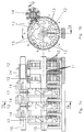
- a first embodiment is in Figure 1a partially cut along line 1a - 1a in Figure 1b and in Figure 1b in cross section along line 1b - 1b in Figure 1a shown.
- Figure 2a shows a second and Figure 2b a third Embodiment.
- Figure 3 shows all possible codes for third embodiment.
- a fourth embodiment is in Figure 4a in view and in Figure 4b in cross section shown.
- Figure 5a shows a fifth embodiment and a sixth exemplary embodiment is shown in FIG. 5b in Partial view and shown in cross section in FIG. 5c.
- the first embodiment works with one-way light barriers, which have optical sensors.
- On a number roll axis 15 are arranged a number of rolls 12, which over Switch pinion 14 are mechanically connected.
- the shift pinion 14 sit on a shift pinion axis 16.
- Die Number rollers 12 are in through an aperture, not shown conventionally visually readable.
- For electronic reading are five light sources on the side of the number rollers 12 10 and on the other hand five sensors or light receivers 11 each with a different radial distance.
- On each number roller 12 is a suitable multi-lane binary code 13 (see Fig. 1b), which consists of translucent and opaque segments (see Figure 1a). This solution poses because of the necessarily small distance of the individual code tracks high demands on accuracy the sensors and the code on the number wheels.
- the Sensors 20 per number roller 12 used as in the first Embodiment are parts of one-way light barriers.
- the Sensors 20 are all on the same sensor print 22 Radial distance on a circular arc around the number roller axis 15 and attached in a radial plane.
- Variants b to k are only for radially symmetrical ones Sensors 30, that is, a distribution with equal angles between the sensors, can be used (see Fig. 2b).
- the codes 21 can also be rotated or mirrored.
- the five sensors 30 are also shown by way of example.
- At One-way light barriers are the segments of the first type Holes formed, the segments of the second type consist of Bridges. It would also be the use of retro-reflective sensors possible, in which case the segments of the first type stand out their reflection properties clearly differ from those of the second type would have to distinguish.
- Design of optical sensors consists of one print 39 arranged parallel to the axis 15 of the number rollers 12 photoelectric elements 40, 41.
- the elements 41 act as Light sources, the light of which is formed by molded light guides 42 is directed to the code-bearing part of the number roller 12 ( Figure 4).
- the elements 40 are optical sensors, e.g. Photoresistors. Place the arrows on the light guides the beam direction of the light.
- FIG. 5a Another inexpensive sensor variant according to a fifth The embodiment is with capacitive sensors 50 equipped ( Figure 5a). Parallel to the number roll is 12 An electrically conductive inner ring 51 with connection 52 near the axis appropriate. The fixed compared to the number rollers 12 Sensors consist of five narrow, among the same Angle spacing arranged with 53 sensor plates electrical connections 54. Inner ring 51 and sensor plate 53 are in a radial plane, preferably on one insulating plate and with a small radial distance to Number roller 12 arranged. The number roller 12 carries one Code disc 55 with three conductive 56 and three not conductive segments 57. To determine the position of a Number roll is the capacity between the inner ring 51 and the individual sensor plates 53 at the connections 52 and 54 measured.
- Figures 5b and 5c show in a sixth Embodiment also with a capacitive variant Radial array sensor 60.
- the Number roller 12 has a side in an annular groove 64 Code cylinder 65 with alternating metallic and non-metallic segments (66, 67). In this case lies the code cylinder 65 is not between sensor plates 63 and Inner ring or cylinder 61, but close enough to the Sensor plate 63 that the measured capacity is sufficient being affected.
Description
Es sind Volumenmessgeräte für Gas und Wasser wie auch
Elektrizitätszähler zur Messung der durchgeströmten Energie
bekannt, in welchen das gemessene Volumen respektive die
gemessene Energie mit einer dem Messgerät angepassten
Untersetzung auf ein mechanisches Rollenzählwerk übertragen
wird. Das Rollenzählwerk zeigt dabei die seit der letzten
Nullstellung respektive die seit der Inbetriebnahme
durchgeflossene Menge an. Zur Bestimmung des Verbrauchs
während einer bestimmten Periode wird der Stand des
Rollenzählwerkes zu Beginn und am Ende dieser Periode
abgelesen. Eine bevorzugte Ausführung für das Rollenzählwerk
besteht aus einer Achse, auf welcher die Zahlenrollen drehbar
angebracht sind und auf deren Umfang die Ziffern 0 bis 9
aufgebracht sind, sowie aus einer zweiten Achse mit darauf
drehbaren Schaltritzeln derart, dass jeweils die
kleinerwertige Zahlenrolle im letzten Zehntel einer Umdrehung
über das zugeordnete Schaltritzel die nächst höherwertige
Rolle um eine Zehntelumdrehung weiterschaltet. Ein
Rollenzählwerk für ein Messgerät für Wasser findet sich zum
Beispiel in der DE 2 244 404 A1. Je nach Ausführung des
Messgerätes ist es zur Erzielung eines grossen Messbereichs
mit einer guten Messgenauigkeit wichtig, das zum Antrieb des
Rollenzählwerkes erforderliche Drehmoment möglichst klein zu
halten.There are volume meters for gas and water as well
Electricity meter for measuring the flow of energy
known in which the measured volume or
measured energy with a device adapted to the measuring device
Transfer the reduction to a mechanical roller counter
becomes. The roller counter shows the number since the last one
Zero position or that since commissioning
flowed through amount of. To determine consumption
During a certain period, the status of the
Roll counter at the beginning and end of this period
read. A preferred version for the roller counter
consists of an axis on which the number rollers can be rotated
are attached and the
Aus US 3 732 404 ist eine Lösung zur elektronischen Auslesung eines Zählwerkes bekannt, in welcher die kontinuierliche Drehbewegung der Zahlenrollen in eine schnappende Bewegung übersetzt wird. Dabei ist sicherzustellen, dass die für die schnappende Bewegung verwendete Feder o.ä. genügend Energie aufnimmt, um das ganze Rollenzählwerk eine Stellung vorwärts zu drehen, beispielsweise von 19999 auf 20000. Aus der EP 202722 B1 ist eine Lösung bekannt, welche die elektronische Auslesung für ein Zählwerk vom Nadeltyp unter der Verwendung von mechanischen Kontakten ohne Schnappbewegung erlaubt. Allen obigen Lösungen ist gemeinsam, dass mit ihnen eine Erhöhung des zum Antrieb des Rollenzählwerkes erforderlichen Drehmomentes verbunden ist.From US 3 732 404 is a solution for electronic reading known a counter in which the continuous Rotation movement of the number rollers in a snap movement is translated. It must be ensured that the for the snapping movement used spring or similar enough energy picks up one position around the entire roller counter to rotate, for example from 19999 to 20000. From the EP 202722 B1 discloses a solution which uses electronic Readout for a needle type counter using mechanical contacts allowed without snap movement. Everyone The above solutions have in common that with them an increase that is required to drive the roller counter Torque is connected.
Aus US-A-4,031,386 ist die optoelektronische Auslesung von Rollenzählwerken bekannt, wobei die Sensoren senkrecht zur Zahlenrollenachse angeordnet sind. US-A-4,031,386 describes the optoelectronic reading of roller counters known, the sensors perpendicular to the number roller axis are arranged.
Die senkrechte Anordnung von einen Gray-Code liefernden Sensoren zu einer sich drehenden Achse ist optoelektronisch für eine Wettermeßeinrichtung aus GB-A-2,130,828 und kapazitiv für Maschinenelemente aus CH-A-614,776 bekannt.The vertical arrangement of a Gray code Sensors to a rotating axis is optoelectronic for a weather measuring device from GB-A-2,130,828 and capacitive for machine elements from CH-A-614,776.
Der vorliegenden Erfindung liegt die Aufgabe zu Grunde, den Anzeigestand eines Rollenzählwerkes in einem Messgerät mit möglichst einfachen Mitteln zu einem beliebigen Zeitpunkt digital elektronisch auszulesen, ohne dass durch die dazu notwendigen Mittel das zum Antrieb des Rollenzählwerkes erforderliche Drehmoment wesentlich verändert wird.The present invention is based on the object Display status of a roller counter in a measuring device the simplest possible means at any time digitally read out electronically without having to do so necessary means that drive the roller counter required torque is changed significantly.
Diese Aufgabe wird durch das Rollenzählwerk gemäß Patentanspruch 1 gelost.This object is achieved by the roller counter according to claim 1.
Gemäss vorliegender Erfindung wird der Anzeigestand eines mechanischen Rollenzählwerkes mittels geeigneter, fest angeordneter berührungsloser Sensoren elektronisch ausgelesen, ohne dass einschränkende Bedingungen an die Drehbewegung des Rollenzählwerkes wie zum Beispiel eine schnappende Drehung erfüllt sein müssen. Um die Anzeige eines nicht schnappenden Rollenzählwerkes in allen Stellungen und unter Berücksichtigung des mechanisch notwendigen Spiels des Rollengetriebes mit statischen Sensoren zuverlässig auszulesen, ist es erforderlich, dass die Sensoren pro Umdrehung der Rolle mindestens 22 verschiedene Signalzustände annehmen. Damit ist es möglich, den Drehwinkel jeder Zahlenrolle mit einer Unsicherheit von weniger als 18° zu messen und die relative Stellung zweier benachbarter Rollen mit einer Unsicherheit von weniger als 36° festzustellen und somit den Anzeigestand des Rollenzählwerkes zuverlässig zu ermitteln. In einer Vorzugslösung nehmen die Sensoren pro Umdrehung 30 unterschiedliche Signalzustände an, symmetrisch verteilt mit einem Drehwinkel der Zahlenrolle von 12° pro Signalzustand. Bei dieser Lösung ist ein mechanisches Spiel von Zahlenrolle zu Zahlenrolle von bis zu knapp 12° zulässig, unabhängig von der Anzahl der auszulesenden Zahlenrollen. According to the present invention, the display status is one mechanical roller counter by means of a suitable, fixed arranged contactless sensors electronically read out, without restricting the rotational movement of the Roll counter such as a snap rotation must be fulfilled. To display a non-snap Roller counter in all positions and under Consideration of the mechanically necessary play of the Roller transmission with static sensors reliable read out, it is necessary that the sensors pro Revolution of the roller at least 22 different signal states accept. It is possible to change the angle of rotation of everyone Number roll with an uncertainty of less than 18 ° too measure and the relative position of two adjacent roles with an uncertainty of less than 36 ° and thus the display status of the roller counter reliably determine. In a preferred solution, the sensors take pro 30 different signal states, symmetrical distributed with a rotation angle of the number roll of 12 ° each Signal state. With this solution there is mechanical play from number roll to number roll of up to just under 12 ° permissible, regardless of the number of number roles to be read.
Eine aus Anwendungen zur Detektion einer mechanischen Position mit mehreren Sensoren allgemein bekannte Anforderung an die Signalzustände ist, dass in der Art eines Gray-Codes von Zustand zu Zustand jeweils nur ein Signal ändert.One from mechanical position detection applications with several sensors commonly known requirement for the Signal states is that in the manner of a gray code of State to state changes only one signal at a time.
Mehrere Ausführungsbeispiele der Erfindung sind in der
Zeichnung dargestellt und in der nachfolgenden Beschreibung
näher erläutert. Ein erstes Ausführungsbeispiel ist in Figur
1a teilgeschnitten gemäss Linie 1a - 1a in Figur 1b und in
Figur 1b im Querschnitt gemäss Linie 1b - 1b in Figur 1a
gezeigt. Figur 2a zeigt ein zweites und Figur 2b ein drittes
Ausführungsbeispiel. Figur 3 zeigt alle möglichen Codes zum
dritten Ausführungsbeispiel. Ein viertes Ausführungsbeispiel
ist in Figur 4a in Ansicht und in Figur 4b im Querschnitt
gezeigt. Figur 5a zeigt ein fünftes Ausführungsbeispiel und
ein sechstes Ausführungsbeispiel ist in Figur 5b in
Teilansicht und in Figur 5c im Querschnitt gezeigt.Several embodiments of the invention are in the
Drawing shown and in the description below
explained in more detail. A first embodiment is in Figure
1a partially cut along
Das erste Ausführungsbeispiel arbeitet mit Einweglichtschranken,
die optische Sensoren aufweisen. Auf einer Zahlenrollenachse
15 sind mehrere Zahlenrollen 12 angeordnet, die über
Schaltritzel 14 mechanisch miteinander in Verbindung stehen.
Die Schaltritzel 14 sitzen auf einer Schaltritzelachse 16. Die
Zahlenrollen 12 sind durch eine nicht dargestellte Blende in
herkömmlicher Weise visuell ablesbar. Zum elektronischen Auslesen
sind seitlich der Zahlenrollen 12 einerseits fünf Lichtquellen
10 und andererseits fünf Sensoren oder Lichtempfänger
11 mit jeweils unterschiedlichem Radialabstand angeordnet. An
jeder Zahlenrolle 12 befindet sich ein geeigneter mehrspuriger
binärer Code 13 (siehe Fig. 1b), der aus lichtdurchlässigen
und lichtundurchlässigen Segmenten besteht (siehe Figur 1a).
Diese Lösung stellt wegen des zwangsläufig geringen Abstand
der einzelnen Codespuren hohe Anforderungen an die Genauigkeit
der Sensoren und des Codes auf den Zahlenrollen.The first embodiment works with one-way light barriers,
which have optical sensors. On a
Gemäss des zweiten Ausführungsbeispiels werden ebenfalls fünf
Sensoren 20 pro Zahlenrolle 12 verwendet, die wie im ersten
Ausführungsbeispiel Teile von Einweglichtschranken sind. Die
Sensoren 20 sind auf einem Sensorprint 22 alle mit gleichem
Radialabstand auf einem Kreisbogen um die Zahlenrollenachse 15
und in einer radialen Ebene angebracht. Für eine rationelle
Montage ist es vorteilhaft, alle fünf Sensoren 20 möglichst
nahe beieinander in einer Hälfte des Umfangs der Zahlenrollen
12 anzubringen. Dies ist in einer Anordnung mit Winkeln von je
36° zwischen den fünf Sensoren 20 gegeben. (Figur 2 a).According to the second embodiment, there are also five
Für eine möglichst zuverlässige Ausführung des Encoders ist es
vorteilhaft, in den 30 verwendeten Signalzuständen die
Zustände "1 1 1 1 1" (alle Sensoren ein) und "0 0 0 0 0" (alle
Sensoren aus) nicht zu berücksichtigen, so dass ein globaler
Test der Sensorfunktion möglich ist. Dazu sind die fünf
Sensoren 20 über den ganzen Umfang gleichmässig verteilt mit
Winkeln von 72° anzuordnen (Figur 2 b). Andere mögliche
Ausführungen haben die Sensoren 20 mit Winkeln von 72°, 36°,
36°, 72° oder 36°, 72°, 36°, 108° angeordnet.It is for the most reliable execution of the encoder
advantageous in the 30 signal states used
States "1 1 1 1 1" (all sensors on) and "0 0 0 0 0" (all
Sensors off) not to be considered, so a global
Test of the sensor function is possible. The five are
Die möglichen Codes 21 auf den Zahlenrollen 12 sind in den
Figuren 3a, 3b, 3c, 3d, 3e, 3f, 3g, 3h, 3i und 3k dargestellt.
Sie bestehen aus drei Segmenten einer ersten Art 31 und aus
drei Segmenten einer zweiten Art 32. Die sechs Trennlinien
zwischen den Segmenten 31, 32 der Codes 21 sind in folgenden
Winkeln auf den Zahlenrollen 12 angeordnet:
Die Varianten b bis k sind nur für radialsymmetrisch verteilte
Sensoren 30, das heisst eine Verteilung mit gleichen Winkeln
zwischen den Sensoren, verwendbar (siehe Fig. 2b). Die Codes
21 können auch gedreht oder gespiegelt werden. In Figur 3b
sind beispielhaft auch die fünf Sensoren 30 gezeigt. Bei
Einweglichtschranken werden die Segmente der ersten Art durch
Löcher gebildet, die Segmente der zweiten Art bestehen aus
Stegen. Es wäre auch die Verwendung von Reflexlichtschranken
möglich, wobei dann die Segmente der ersten Art sich durch
ihre Relexionseigenschaften von denen der zweiten Art deutlich
unterscheiden müssten.Variants b to k are only for radially
Eine für die Herstellung grösserer Stückzahlen vorteilhafte
Gestaltung von optischen Sensoren besteht aus auf einem Print
39 parallel zur Achse 15 der Zahlenrollen 12 angeordneten
fotoelektrischen Elementen 40, 41. Die Elemente 41 wirken als
Lichtquellen, deren Licht durch formgepresste Lichtleiter 42
auf den codetragenden Teil der Zahlenrolle 12 gelenkt wird
(Figur 4). Die Elemente 40 sind optische Sensoren, z.B.
Photowiderstände. Die Pfeile auf den Lichtleitern geben
jeweils die Strahlrichtung des Lichts an.An advantageous one for the production of larger quantities
Design of optical sensors consists of one
Eine andere kostengünstige Sensorvariante gemäss einem fünften
Ausführungsbeispiel ist mit kapazitiven Sensoren 50
ausgestattet (Figur 5a). Parallel zur Zahlenrolle 12 ist
achsnah ein elektrisch leitender Innenring 51 mit Anschluss 52
angebracht. Die gegenüber den Zahlenrollen 12 feststehenden
Sensoren bestehen aus fünf schmalen, unter gleichen
Winkelabständen angeordneten Fühlerplättchen 53 mit
elektrischen Anschlüssen 54. Innenring 51 und Fühlerplättchen
53 sind in einer Radialebene, vorzugsweise auf einer
isolierenden Platte und mit geringem Radialabstand zur
Zahlenrolle 12 angeordnet. Die Zahlenrolle 12 trägt eine
Codescheibe 55 mit je drei leitenden 56 und drei nicht
leitenden Segmenten 57. Zur Bestimmung der Stellung einer
Zahlenrolle wird die Kapazität zwischen dem Innenring 51 und
den einzelnen Fühlerplättchen 53 an den Anschlüssen 52 und 54
gemessen. Another inexpensive sensor variant according to a fifth
The embodiment is with capacitive sensors 50
equipped (Figure 5a). Parallel to the number roll is 12
An electrically conductive
Die Figuren 5b und 5c zeigen in einem sechsten
Ausführungsbeispiel ebenfalls eine kapazitive Variante mit
Sensor 60 in Radialanordnung. Die Kapazitäten jeweils zwischen
einem metallischen Innenzylinder 61 und fünf radial davon
beabstandeten schmalen Fühlerplättchen 63 gemessen. Die
Zahlenrolle 12 weist seitlich in einer Ringnut 64 einen
Codezylinder 65 mit abwechselnd metallischen und
nichtmetallischen Segmenten (66, 67) auf. In diesem Fall liegt
der Codezylinder 65 nicht zwischen Fühlerplättchen 63 und
Innenring bzw. -zylinder 61, aber nahe genug bei den
Fühlerplättchen 63, dass die gemessene Kapazität ausreichend
beeinflusst wird.Figures 5b and 5c show in a sixth
Embodiment also with a capacitive variant
Radial array sensor 60. The capacities between each
a metallic
Anstatt der kapazitiven Sensoren können ebensogut auch entsprechend ausgebildete induktive Sensoren verwandt werden.Instead of the capacitive sensors, you can as well appropriately trained inductive sensors can be used.
Claims (7)
- Multidigit counting wheel mechanism for a volume-measuring instrument for gas or water or for an electricity meter, in which of each two counting wheels the higher digit counting wheel is turned further through one tenth of a revolution by way of a "carry" pinion by the lower digit one in the last tenth of its revolution, and wherein contactless sensors (11, 20, 30, 50, 60) for each counting wheel (12) to be read out are mounted on a diameter in a plane perpendicular to the counting wheel axle (15), characterised in that three segments (31, 56, 66) of a first kind with a light-permeable or non-reflective characteristic and three segments (32, 57, 67) of a second kind with a light-blocking or reflective characteristic, which segments produce a binary code (13, 21, 55, 65) through reading by means of five sensors (11, 20, 30, 50, 60), are mounted on the counting wheels (12) in such a manner that the five sensors (11, 20, 30, 50, 60) generate up to thirty-two different signal states in one complete revolution of a counting wheel (12) with at least one variant of the pitch angle of the segment dividing lines, wherein the five sensors (11, 20, 30, 50, 60) are executed as photoelectric elements (40, 41) and mould-pressed optical conductors (42) arranged on a print (39) parallel to the axis (15) of the counting wheels (12).
- Multidigit wheel display mechanism according to claim 1 or 2, characterised in that one of the following variants a-k is present for the pitch angle of the segment dividing lines:Variant a: 18°, 78°, 174°, 198°, 258°, 354°Variant b: 18°, 42°, 78°, 126°, 246°, 354°Variant c: 18°, 42°, 78°, 198°, 318°, 354°Variant d: 18°, 54°, 174°, 258°, 294°, 354°Variant e: 18°, 42°, 150°, 198°, 246°, 354°Variant f: 18°, 54°, 102°, 150°, 258°, 354°Variant g: 18°, 54°, 114°, 150°, 246°, 354°Variant h: 18°, 54°, 150°, 186°, 246°, 354°Variant i: 30°, 78°, 114°, 162°, 270°, 354°Variant k: 30°, 78°, 126°, 162°, 258°, 354°
- Multidigit wheel display mechanism according to claim 1 or 2, characterised in that the code consists of unequally long segments (31, 32; 56, 57, 67), which are arranged on a circular arc.
- Multidigit wheel display mechanism according to one of claims 1 to 3, characterised in that the sensors (11, 20, 30, 50, 60) are all arranged on a circular arc at equal radial spacing from the counting wheel axle (15).
- Multidigit wheel display mechanism according to one of claims 1 to 4, characterised in that the sensors (11, 20, 30) are constructed as optical sensors, in particular as photodetectors, which are part of a one-way light barrier.
- Multidigit wheel display mechanism according to one of claims 1 to 4, characterised in that the sensors (50, 60) are constructed as capacitive sensors.
- Multidigit wheel display mechanism according to claim 6, characterised in that the five capacitive sensors (50, 60) are constructed as narrow metallised sensor platelets (53, 63) and a code disc (55) or a code cylinder (65), either of which has metallic segments (56, 66) and non-metallic segments (57, 67) in alternation, is disposed in the immediate proximity of the sensor platelets (53, 63) and that the capacitance is measured between the sensor platelets (53, 63) and an electrically conductive inner ring (51, 61).
Applications Claiming Priority (3)
| Application Number | Priority Date | Filing Date | Title |
|---|---|---|---|
| CH3854/93 | 1993-12-23 | ||
| CH385493 | 1993-12-23 | ||
| CH385493 | 1993-12-23 |
Publications (2)
| Publication Number | Publication Date |
|---|---|
| EP0660263A1 EP0660263A1 (en) | 1995-06-28 |
| EP0660263B1 true EP0660263B1 (en) | 2000-03-01 |
Family
ID=4264910
Family Applications (1)
| Application Number | Title | Priority Date | Filing Date |
|---|---|---|---|
| EP94119110A Expired - Lifetime EP0660263B1 (en) | 1993-12-23 | 1994-12-05 | Method for providing electrical signal readout of a multi-digit drum-counter for use in a flow-meter |
Country Status (11)
| Country | Link |
|---|---|
| US (1) | US5565861A (en) |
| EP (1) | EP0660263B1 (en) |
| KR (1) | KR100360511B1 (en) |
| CN (1) | CN1076840C (en) |
| AU (1) | AU678078B2 (en) |
| CA (1) | CA2138888C (en) |
| DE (1) | DE59409167D1 (en) |
| DK (1) | DK0660263T3 (en) |
| ES (1) | ES2145805T3 (en) |
| GR (1) | GR3033532T3 (en) |
| PT (1) | PT660263E (en) |
Cited By (3)
| Publication number | Priority date | Publication date | Assignee | Title |
|---|---|---|---|---|
| EP1965180A1 (en) | 2007-02-09 | 2008-09-03 | GWF MessSysteme AG | Method for recognising an exterior action on the counter of a meter for a flowing medium and such a meter |
| EP2023096A1 (en) | 2007-08-09 | 2009-02-11 | GWF MessSysteme AG | Measuring device with lead sealing and method for lead sealing the measuring device for a flowing medium |
| EP2581717A1 (en) | 2011-10-11 | 2013-04-17 | GWF MessSysteme AG | Method for determining the displayed digits of digit rollers of a roller counter |
Families Citing this family (37)
| Publication number | Priority date | Publication date | Assignee | Title |
|---|---|---|---|---|
| US5640007A (en) * | 1995-06-21 | 1997-06-17 | Limitorque Corporation | Optical encoder comprising a plurality of encoder wheels |
| EP0774648B1 (en) * | 1995-11-17 | 2000-07-12 | Leopold Kostal GmbH & Co. KG | Angle sensor |
| US5764164A (en) * | 1997-02-07 | 1998-06-09 | Reality Quest Corp. | Ergonomic hand-attachable controller |
| US5796354A (en) * | 1997-02-07 | 1998-08-18 | Reality Quest Corp. | Hand-attachable controller with direction sensing |
| US6465772B1 (en) * | 1997-10-23 | 2002-10-15 | Nsi Corporation | Optical encoder having multiple thumbwheels with integral encoder patterns |
| ES2304186T3 (en) | 1998-02-27 | 2008-09-16 | Mr Engineering Ag | READING DEVICE FOR A ROLLER COUNTER. |
| EP0939380B1 (en) * | 1998-02-27 | 2008-03-26 | MR Engineering AG | Reading apparatus for a drum counter |
| DE10006503A1 (en) * | 2000-02-14 | 2001-08-16 | Abb Research Ltd | Capacitive counting wheel position determination device for gas meter, measures capacitance change between measurement electrodes arranged between non-conductive sections of counting wheel and fixed electrodes |
| US6674371B1 (en) * | 2000-08-18 | 2004-01-06 | Hersey Meter Company | Utility meter remote reader |
| GB2382768B (en) * | 2001-12-06 | 2004-03-03 | Ofquest Ltd | Folding desk |
| GB2414187B (en) * | 2004-05-21 | 2007-03-07 | Bespak Plc | Dispensing apparatus |
| DE102004055745A1 (en) * | 2004-11-18 | 2006-06-01 | Krones Ag | Rotary encoder and rotary machine |
| WO2007068242A1 (en) * | 2005-12-16 | 2007-06-21 | Flonidan Dc A/S | Method for volumetric measuring of gas and diaphragm gas meter |
| GB0606055D0 (en) * | 2006-03-25 | 2006-05-03 | Scient Generics Ltd | Non-contact wheel encoder |
| WO2007123533A1 (en) * | 2006-04-21 | 2007-11-01 | Flowserve Management Company | Rotary encoder frequency analysis |
| CA2649642C (en) * | 2006-04-21 | 2016-08-09 | Flowserve Management Company | Rotary encoder with built-in-self-test |
| CN102865400B (en) * | 2006-04-21 | 2014-11-12 | 芙罗服务管理公司 | Valve actuator |
| GB0610541D0 (en) | 2006-05-26 | 2006-07-05 | Bespak Plc | Improvements in or relating to dispensing apparatus |
| GB2438396B (en) * | 2006-05-26 | 2008-10-01 | Bespak Plc | Improvements in or relating to dispensing apparatus |
| ES1063614Y (en) * | 2006-07-04 | 2007-02-16 | Eady Jose Manuel Maura | PERFECTED COUNTER DEVICE |
| CN100549629C (en) * | 2007-04-04 | 2009-10-14 | 上海元上电子科技有限公司 | Ternary system clobber-free number wheel code disk sensor |
| CN101319918B (en) * | 2008-07-22 | 2010-06-02 | 陈健 | Tele-metering direct-reading encoder of meter counter |
| DE102009003976A1 (en) | 2009-01-07 | 2010-07-08 | Hengstler Gmbh | Device for the optical scanning of graduations of a mechanical roller counter |
| CN102261940A (en) * | 2011-06-01 | 2011-11-30 | 上海城市水资源开发利用国家工程中心有限公司 | High-reliability electric direct-reading type meter counter |
| CN102306272B (en) * | 2011-08-16 | 2013-08-14 | 成都千嘉科技有限公司 | Encoding method for batching counter |
| CN102661425B (en) * | 2012-03-15 | 2014-06-11 | 沈居富 | Balance valve adjuster, intelligent balance valve adjusting system composed of the same, and method |
| CN103134562A (en) * | 2013-02-06 | 2013-06-05 | 杭州权衡科技有限公司 | Method for directly reading mechanical metering device by utilizing optical path |
| CN103674151A (en) * | 2013-11-15 | 2014-03-26 | 安徽鸿凌智能仪表科技有限公司 | Passive direct-reading remote-transmitting water meter |
| US9441998B2 (en) * | 2014-07-21 | 2016-09-13 | Ecolab Usa Inc. | Oval gear meter |
| CN104501895B (en) * | 2014-11-19 | 2017-11-28 | 湖北泽捷电子科技有限公司 | Optical fiber direct-reading gauge head |
| CN104501896A (en) * | 2014-11-19 | 2015-04-08 | 湖北泽捷电子科技有限公司 | Optical fiber direct-reading water gauge |
| EP3096450A1 (en) * | 2015-05-20 | 2016-11-23 | Aiut Sp. z o.o. | Electric circuit of a generator of oscillations |
| CN106372716B (en) * | 2016-08-30 | 2018-09-04 | 浙江威星智能仪表股份有限公司 | A kind of counter coding extended method based on character wheel counting device |
| CN106650909B (en) * | 2017-02-27 | 2023-05-30 | 中冶华天工程技术有限公司 | Enclosed shell type photoelectric rotary dial counting device |
| CN110569955A (en) * | 2018-06-05 | 2019-12-13 | 金卡智能集团股份有限公司 | character wheel position judging and counting device based on capacitance and metering instrument |
| CN113884154B (en) * | 2020-07-03 | 2023-10-31 | 成都秦川物联网科技股份有限公司 | MCU-based double-path photoelectric sampling method for intelligent gas meter of Internet of things |
| KR20220000415U (en) | 2020-08-10 | 2022-02-17 | 김용 | Circular structure for heating water boiler |
Family Cites Families (7)
| Publication number | Priority date | Publication date | Assignee | Title |
|---|---|---|---|---|
| US3732404A (en) * | 1971-09-20 | 1973-05-08 | Ripley Co Inc | Meter device |
| DE2244404C3 (en) * | 1972-09-09 | 1982-03-25 | E. Wehrle Gmbh, 7743 Furtwangen | Roller counter for liquid meters |
| US4031386A (en) * | 1976-06-15 | 1977-06-21 | Rockwell International Corporation | Optical transducer encoding apparatus |
| CH614776A5 (en) * | 1977-01-05 | 1979-12-14 | Husqvarna Ab | Arrangement for determining and representing the position of a first term compared with a second term in an n-digit code |
| GB2130828B (en) * | 1982-10-23 | 1986-06-18 | Danjay Designs Limited | Weather monitor |
| DE3310208A1 (en) * | 1983-03-21 | 1984-10-04 | Siemens AG, 1000 Berlin und 8000 München | READING DEVICE FOR THE COUNTER READING OF A ROLL COUNTER |
| BE902500A (en) * | 1985-05-24 | 1985-09-16 | Aquacom Sa | Counter-totaliser for metering fluids or electricity - has gear-train division with code wheels carrying switch contacts giving digital output |
-
1994
- 1994-12-05 ES ES94119110T patent/ES2145805T3/en not_active Expired - Lifetime
- 1994-12-05 EP EP94119110A patent/EP0660263B1/en not_active Expired - Lifetime
- 1994-12-05 PT PT94119110T patent/PT660263E/en unknown
- 1994-12-05 DE DE59409167T patent/DE59409167D1/en not_active Expired - Lifetime
- 1994-12-05 DK DK94119110T patent/DK0660263T3/en active
- 1994-12-06 US US08/354,039 patent/US5565861A/en not_active Expired - Lifetime
- 1994-12-20 CN CN94119546A patent/CN1076840C/en not_active Expired - Lifetime
- 1994-12-21 KR KR1019940035710A patent/KR100360511B1/en not_active IP Right Cessation
- 1994-12-21 AU AU81641/94A patent/AU678078B2/en not_active Expired
- 1994-12-22 CA CA002138888A patent/CA2138888C/en not_active Expired - Lifetime
-
2000
- 2000-05-30 GR GR20000401224T patent/GR3033532T3/en not_active IP Right Cessation
Cited By (4)
| Publication number | Priority date | Publication date | Assignee | Title |
|---|---|---|---|---|
| EP1965180A1 (en) | 2007-02-09 | 2008-09-03 | GWF MessSysteme AG | Method for recognising an exterior action on the counter of a meter for a flowing medium and such a meter |
| EP2023096A1 (en) | 2007-08-09 | 2009-02-11 | GWF MessSysteme AG | Measuring device with lead sealing and method for lead sealing the measuring device for a flowing medium |
| EP2581717A1 (en) | 2011-10-11 | 2013-04-17 | GWF MessSysteme AG | Method for determining the displayed digits of digit rollers of a roller counter |
| WO2013053806A1 (en) | 2011-10-11 | 2013-04-18 | Gwf Messsysteme Ag | Method for determining digits of number rollers of a mechanical roller-type counter |
Also Published As
| Publication number | Publication date |
|---|---|
| CN1127351A (en) | 1996-07-24 |
| KR100360511B1 (en) | 2003-02-25 |
| AU8164194A (en) | 1995-06-29 |
| DK0660263T3 (en) | 2000-08-14 |
| CA2138888C (en) | 2005-03-01 |
| GR3033532T3 (en) | 2000-09-29 |
| CA2138888A1 (en) | 1995-06-24 |
| KR950019646A (en) | 1995-07-24 |
| AU678078B2 (en) | 1997-05-15 |
| CN1076840C (en) | 2001-12-26 |
| DE59409167D1 (en) | 2000-04-06 |
| EP0660263A1 (en) | 1995-06-28 |
| ES2145805T3 (en) | 2000-07-16 |
| US5565861A (en) | 1996-10-15 |
| PT660263E (en) | 2000-08-31 |
Similar Documents
| Publication | Publication Date | Title |
|---|---|---|
| EP0660263B1 (en) | Method for providing electrical signal readout of a multi-digit drum-counter for use in a flow-meter | |
| EP0953494B1 (en) | Apparatus for sensing the amount of torsion between two parts | |
| EP2052218B1 (en) | Optoelectronic angle sensor and method for determining a rotation angle around an axis | |
| DE3921756C1 (en) | ||
| DE3526338C2 (en) | ||
| DE102015107908A1 (en) | Device for measuring rotary angles in counters and multistage encoders and associated sensors | |
| DE2339948A1 (en) | DIGITAL MAGNETIC COMPASS | |
| EP1355134A1 (en) | Liquid level meter | |
| EP0633545B1 (en) | Multi-digit roller-counter having an encoder | |
| DE19626654A1 (en) | Multiturn revolution transposer for angular position encoder | |
| EP1688708A2 (en) | Device for determining an absolute rotation angle | |
| DE2758853C2 (en) | Device for measuring the dimension, e.g. the width of a body | |
| DE102018212788A1 (en) | Optical position measuring device | |
| EP0660264B1 (en) | Method for providing electrical signal readout of a multi-digit drum-counter for use in a flow or electricity-meter | |
| EP1770372A2 (en) | Position measuring device | |
| DE1774578B2 (en) | Liquid meter with electronic remote transmission | |
| DE3334400C1 (en) | Photoelectric position-measuring device | |
| DE10230471B4 (en) | Measuring system for absolute value acquisition of angles or paths | |
| DE2553815C3 (en) | Graycode transducer | |
| AT242036B (en) | Registration device on a winding device for yarns or films | |
| DE4428396A1 (en) | Non-contact measuring unit for transmitter wheel rotation speed and its direction | |
| EP0939380B1 (en) | Reading apparatus for a drum counter | |
| DE10006503A1 (en) | Capacitive counting wheel position determination device for gas meter, measures capacitance change between measurement electrodes arranged between non-conductive sections of counting wheel and fixed electrodes | |
| DE19918313A1 (en) | Angle sensing instrument for monitoring position of shaft with limited rotation has codes printed or inscribed on disc and read by optical detector | |
| DE102019207322B4 (en) | Optical reading device for a pointer instrument |
Legal Events
| Date | Code | Title | Description |
|---|---|---|---|
| PUAI | Public reference made under article 153(3) epc to a published international application that has entered the european phase |
Free format text: ORIGINAL CODE: 0009012 |
|
| AK | Designated contracting states |
Kind code of ref document: A1 Designated state(s): BE CH DE DK ES FR GB GR IT LI NL PT |
|
| 17P | Request for examination filed |
Effective date: 19951117 |
|
| 17Q | First examination report despatched |
Effective date: 19981013 |
|
| GRAG | Despatch of communication of intention to grant |
Free format text: ORIGINAL CODE: EPIDOS AGRA |
|
| GRAG | Despatch of communication of intention to grant |
Free format text: ORIGINAL CODE: EPIDOS AGRA |
|
| GRAH | Despatch of communication of intention to grant a patent |
Free format text: ORIGINAL CODE: EPIDOS IGRA |
|
| GRAH | Despatch of communication of intention to grant a patent |
Free format text: ORIGINAL CODE: EPIDOS IGRA |
|
| GRAA | (expected) grant |
Free format text: ORIGINAL CODE: 0009210 |
|
| AK | Designated contracting states |
Kind code of ref document: B1 Designated state(s): BE CH DE DK ES FR GB GR IT LI NL PT |
|
| REG | Reference to a national code |
Ref country code: CH Ref legal event code: EP |
|
| REF | Corresponds to: |
Ref document number: 59409167 Country of ref document: DE Date of ref document: 20000406 |
|
| REG | Reference to a national code |
Ref country code: CH Ref legal event code: NV Representative=s name: INVENTIO AKTIENGESELLSCHAFT |
|
| ITF | It: translation for a ep patent filed |
Owner name: MODIANO & ASSOCIATI S.R.L. |
|
| GBT | Gb: translation of ep patent filed (gb section 77(6)(a)/1977) |
Effective date: 20000503 |
|
| ET | Fr: translation filed | ||
| REG | Reference to a national code |
Ref country code: ES Ref legal event code: FG2A Ref document number: 2145805 Country of ref document: ES Kind code of ref document: T3 |
|
| REG | Reference to a national code |
Ref country code: DK Ref legal event code: T3 |
|
| REG | Reference to a national code |
Ref country code: PT Ref legal event code: SC4A Free format text: AVAILABILITY OF NATIONAL TRANSLATION Effective date: 20000529 |
|
| PGFP | Annual fee paid to national office [announced via postgrant information from national office to epo] |
Ref country code: GR Payment date: 20001129 Year of fee payment: 7 |
|
| PLBE | No opposition filed within time limit |
Free format text: ORIGINAL CODE: 0009261 |
|
| STAA | Information on the status of an ep patent application or granted ep patent |
Free format text: STATUS: NO OPPOSITION FILED WITHIN TIME LIMIT |
|
| 26N | No opposition filed | ||
| PG25 | Lapsed in a contracting state [announced via postgrant information from national office to epo] |
Ref country code: GR Free format text: LAPSE BECAUSE OF NON-PAYMENT OF DUE FEES Effective date: 20011231 |
|
| REG | Reference to a national code |
Ref country code: GB Ref legal event code: IF02 |
|
| PGFP | Annual fee paid to national office [announced via postgrant information from national office to epo] |
Ref country code: DK Payment date: 20131219 Year of fee payment: 20 Ref country code: PT Payment date: 20130606 Year of fee payment: 20 Ref country code: GB Payment date: 20131219 Year of fee payment: 20 Ref country code: CH Payment date: 20131219 Year of fee payment: 20 Ref country code: DE Payment date: 20131220 Year of fee payment: 20 |
|
| PGFP | Annual fee paid to national office [announced via postgrant information from national office to epo] |
Ref country code: IT Payment date: 20131217 Year of fee payment: 20 Ref country code: NL Payment date: 20131219 Year of fee payment: 20 Ref country code: ES Payment date: 20131226 Year of fee payment: 20 |
|
| PGFP | Annual fee paid to national office [announced via postgrant information from national office to epo] |
Ref country code: BE Payment date: 20131219 Year of fee payment: 20 |
|
| PGFP | Annual fee paid to national office [announced via postgrant information from national office to epo] |
Ref country code: FR Payment date: 20131220 Year of fee payment: 20 |
|
| REG | Reference to a national code |
Ref country code: DE Ref legal event code: R071 Ref document number: 59409167 Country of ref document: DE |
|
| REG | Reference to a national code |
Ref country code: DK Ref legal event code: EUP Effective date: 20141205 |
|
| REG | Reference to a national code |
Ref country code: CH Ref legal event code: PL Ref country code: PT Ref legal event code: MM4A Free format text: MAXIMUM VALIDITY LIMIT REACHED Effective date: 20141205 |
|
| REG | Reference to a national code |
Ref country code: NL Ref legal event code: V4 Effective date: 20141205 |
|
| REG | Reference to a national code |
Ref country code: GB Ref legal event code: PE20 Expiry date: 20141204 |
|
| PG25 | Lapsed in a contracting state [announced via postgrant information from national office to epo] |
Ref country code: GB Free format text: LAPSE BECAUSE OF EXPIRATION OF PROTECTION Effective date: 20141204 Ref country code: PT Free format text: LAPSE BECAUSE OF EXPIRATION OF PROTECTION Effective date: 20141215 |
|
| REG | Reference to a national code |
Ref country code: ES Ref legal event code: FD2A Effective date: 20150826 |
|
| PG25 | Lapsed in a contracting state [announced via postgrant information from national office to epo] |
Ref country code: ES Free format text: LAPSE BECAUSE OF EXPIRATION OF PROTECTION Effective date: 20141206 |