EP0660204B1 - Electronic device having wearing band - Google Patents
Electronic device having wearing band Download PDFInfo
- Publication number
- EP0660204B1 EP0660204B1 EP94919849A EP94919849A EP0660204B1 EP 0660204 B1 EP0660204 B1 EP 0660204B1 EP 94919849 A EP94919849 A EP 94919849A EP 94919849 A EP94919849 A EP 94919849A EP 0660204 B1 EP0660204 B1 EP 0660204B1
- Authority
- EP
- European Patent Office
- Prior art keywords
- band
- members
- piece
- fitting band
- electronic apparatus
- Prior art date
- Legal status (The legal status is an assumption and is not a legal conclusion. Google has not performed a legal analysis and makes no representation as to the accuracy of the status listed.)
- Expired - Lifetime
Links
- 239000011248 coating agent Substances 0.000 claims description 19
- 238000000576 coating method Methods 0.000 claims description 19
- 238000005452 bending Methods 0.000 claims description 17
- 238000003780 insertion Methods 0.000 claims description 14
- 230000037431 insertion Effects 0.000 claims description 14
- 230000000670 limiting effect Effects 0.000 claims description 13
- 238000007789 sealing Methods 0.000 claims description 11
- 230000008602 contraction Effects 0.000 claims description 7
- 230000002452 interceptive effect Effects 0.000 claims description 5
- 239000012212 insulator Substances 0.000 claims description 4
- 230000005856 abnormality Effects 0.000 claims description 2
- 210000000707 wrist Anatomy 0.000 description 46
- 230000003247 decreasing effect Effects 0.000 description 26
- 238000013461 design Methods 0.000 description 18
- 239000000463 material Substances 0.000 description 17
- 239000003990 capacitor Substances 0.000 description 16
- 238000012856 packing Methods 0.000 description 15
- 239000010985 leather Substances 0.000 description 11
- 229920005989 resin Polymers 0.000 description 11
- 239000011347 resin Substances 0.000 description 11
- 229920003002 synthetic resin Polymers 0.000 description 10
- 239000000057 synthetic resin Substances 0.000 description 10
- 238000000034 method Methods 0.000 description 9
- 239000004020 conductor Substances 0.000 description 8
- 238000010276 construction Methods 0.000 description 8
- 238000005520 cutting process Methods 0.000 description 8
- 238000009413 insulation Methods 0.000 description 8
- 238000004519 manufacturing process Methods 0.000 description 7
- 230000007423 decrease Effects 0.000 description 6
- 238000006073 displacement reaction Methods 0.000 description 6
- 239000004744 fabric Substances 0.000 description 6
- 239000007769 metal material Substances 0.000 description 6
- 230000001788 irregular Effects 0.000 description 5
- 230000000694 effects Effects 0.000 description 4
- 230000007246 mechanism Effects 0.000 description 4
- 238000003860 storage Methods 0.000 description 4
- 230000008859 change Effects 0.000 description 3
- 230000007797 corrosion Effects 0.000 description 3
- 238000005260 corrosion Methods 0.000 description 3
- 230000006866 deterioration Effects 0.000 description 3
- 229920001971 elastomer Polymers 0.000 description 3
- 239000000806 elastomer Substances 0.000 description 3
- 239000002649 leather substitute Substances 0.000 description 3
- 238000000465 moulding Methods 0.000 description 3
- 239000000758 substrate Substances 0.000 description 3
- 210000004243 sweat Anatomy 0.000 description 3
- XLYOFNOQVPJJNP-UHFFFAOYSA-N water Substances O XLYOFNOQVPJJNP-UHFFFAOYSA-N 0.000 description 3
- 229920000459 Nitrile rubber Polymers 0.000 description 2
- 238000005219 brazing Methods 0.000 description 2
- 229920005549 butyl rubber Polymers 0.000 description 2
- 238000004891 communication Methods 0.000 description 2
- 230000008878 coupling Effects 0.000 description 2
- 238000010168 coupling process Methods 0.000 description 2
- 238000005859 coupling reaction Methods 0.000 description 2
- 230000005611 electricity Effects 0.000 description 2
- 239000000835 fiber Substances 0.000 description 2
- 239000011888 foil Substances 0.000 description 2
- 239000007788 liquid Substances 0.000 description 2
- 229910052751 metal Inorganic materials 0.000 description 2
- 239000002184 metal Substances 0.000 description 2
- 230000002441 reversible effect Effects 0.000 description 2
- 229910000679 solder Inorganic materials 0.000 description 2
- 229920003026 Acene Polymers 0.000 description 1
- WHXSMMKQMYFTQS-UHFFFAOYSA-N Lithium Chemical compound [Li] WHXSMMKQMYFTQS-UHFFFAOYSA-N 0.000 description 1
- XUIMIQQOPSSXEZ-UHFFFAOYSA-N Silicon Chemical compound [Si] XUIMIQQOPSSXEZ-UHFFFAOYSA-N 0.000 description 1
- 229920006311 Urethane elastomer Polymers 0.000 description 1
- 230000015572 biosynthetic process Effects 0.000 description 1
- 230000036772 blood pressure Effects 0.000 description 1
- 230000036760 body temperature Effects 0.000 description 1
- 238000001816 cooling Methods 0.000 description 1
- 238000007599 discharging Methods 0.000 description 1
- 238000009826 distribution Methods 0.000 description 1
- -1 e.g. Polymers 0.000 description 1
- 210000004177 elastic tissue Anatomy 0.000 description 1
- 238000010438 heat treatment Methods 0.000 description 1
- WABPQHHGFIMREM-UHFFFAOYSA-N lead(0) Chemical compound [Pb] WABPQHHGFIMREM-UHFFFAOYSA-N 0.000 description 1
- 229910052744 lithium Inorganic materials 0.000 description 1
- 239000006247 magnetic powder Substances 0.000 description 1
- 230000000873 masking effect Effects 0.000 description 1
- 238000002844 melting Methods 0.000 description 1
- 230000008018 melting Effects 0.000 description 1
- 229910052755 nonmetal Inorganic materials 0.000 description 1
- 238000005498 polishing Methods 0.000 description 1
- 238000010248 power generation Methods 0.000 description 1
- 230000008569 process Effects 0.000 description 1
- 238000011084 recovery Methods 0.000 description 1
- 229910001285 shape-memory alloy Inorganic materials 0.000 description 1
- 229910052710 silicon Inorganic materials 0.000 description 1
- 239000010703 silicon Substances 0.000 description 1
- 238000009751 slip forming Methods 0.000 description 1
- 238000004078 waterproofing Methods 0.000 description 1
- 238000003466 welding Methods 0.000 description 1
Images


Classifications
-
- G—PHYSICS
- G04—HOROLOGY
- G04G—ELECTRONIC TIME-PIECES
- G04G17/00—Structural details; Housings
- G04G17/08—Housings
- G04G17/083—Watches distributed over several housings
-
- G—PHYSICS
- G04—HOROLOGY
- G04G—ELECTRONIC TIME-PIECES
- G04G99/00—Subject matter not provided for in other groups of this subclass
-
- A—HUMAN NECESSITIES
- A44—HABERDASHERY; JEWELLERY
- A44C—PERSONAL ADORNMENTS, e.g. JEWELLERY; COINS
- A44C5/00—Bracelets; Wrist-watch straps; Fastenings for bracelets or wrist-watch straps
- A44C5/0053—Flexible straps
-
- A—HUMAN NECESSITIES
- A44—HABERDASHERY; JEWELLERY
- A44C—PERSONAL ADORNMENTS, e.g. JEWELLERY; COINS
- A44C5/00—Bracelets; Wrist-watch straps; Fastenings for bracelets or wrist-watch straps
- A44C5/14—Bracelets; Wrist-watch straps; Fastenings for bracelets or wrist-watch straps characterised by the way of fastening to a wrist-watch or the like
-
- G—PHYSICS
- G04—HOROLOGY
- G04G—ELECTRONIC TIME-PIECES
- G04G17/00—Structural details; Housings
- G04G17/02—Component assemblies
- G04G17/06—Electric connectors, e.g. conductive elastomers
Definitions
- the present invention relates to an electronic apparatus having a fitting band, and particularly to the construction of an electronic wrist watch containing a battery, a wrist watch having the function to measure the pulse or body temperature or the communicating function, or other electronic apparatus having a conductive member disposed in a fitting band.
- All materials of the bands disclosed in the above publications are non-metallic materials such as natural leather, artificial leather, insulating high-molecular resins, and elastomer fibers.
- the band structures disclosed include a structure in which a magnetic powder is contained in leather, and a metallic piece is added to the widthwise side of a band, a structure in which a flexible metallic plate such as a foil or mesh is contained in leather, a structure in which a conductive high-molecular resin is contained in an insulating high-molecular resin, a structure in which a flexible circuit substrate is contained in a resin, a structure in which a flexible sheet is contained in a synthetic resin to provide a switching function, and a structure in which a wire is contained in a fabric having elasticity and comprising elastomer fibers.
- Japanese Patent Laid-Open Nos. 63-197103 and 1-279603 also disclose a structure in which a conductor is passed zigzag through continuous links of a metallic expansion band.
- the structures for mounting a band on the case of a wrist watch type electronic apparatus include a structure in which a band is mounted by a spring bar, a structure in which a band is mounted by holding it between a case band and a case back, both of which form a case of a wrist watch type electronic apparatus, a structure in which a band is screwed to a case of a wrist watch type electronic apparatus, and a structure in which a case of a wrist watch type electronic apparatus and a band are integrated by holding the case of the wrist watch type electronic apparatus from the upper and lower sides thereof.
- All band mounting portions of the cases of wrist watch type electronic apparatus have a known "Roof-attached Horn style" structure on the case of a wrist watch except a structure in which the band and the case of a wrist type electronic apparatus are integrated by holding the case of a wrist watch type electronic apparatus from the upper and lower sides thereof.
- Some electronic wrist watches have a solar cell or a generating device provided in the case of the watch so as to convert rotation of a oscillating weight into a coil current.
- the electric power generated by the generating device is stored in a secondary battery (for example, a large-capacity capacitor having an electrical double layer) which is contained in the case of the watch so that the driving motor, IC and a display of the watch are driven by the stored electric power.
- Japanese Utility Model Laid-Open Nos. 58-77493 and 3-30892 disclose a structure in which a circuit is contained in a band
- Japanese Utility Model Laid-Open Nos. 59-137588 and 59-137589 disclose a structure in which a piezoelectric element, an electromagnet coil, a rectifying circuit and a battery are contained in a band.
- the material and structure of a band containing a conductive member, which are used for conventional wrist watch type electronic apparatus, the structure for mounting the band on the case of the wrist watch type electronic apparatus, and the structure of the band mounting portion of the case of the wrist watch type electronic apparatus have the problems below to be solved with respect to the property of fitting on an arm, the fitness of the band, strength, durability, limits on design and so on.
- the band material has the problem that although most conventional bands are made of a non-metallic material from the viewpoint of the need to ensure insulating properties, the band design which is important for creating demand can be selected from only a narrow range in view of the present situation where metallic bands are frequently used for wrist watches for the reasons of use environment, durability and design. This is undesirable for the merchandise variation.
- each of the above conventional band mounting structures of the bodies of the wrist watch type electronic apparatus has the following problems:
- the structure of the band mounting portion of the wrist watch type electronic apparatus has the following problems: Although the cases of conventional watches are made of a metal with high rigidity, the bands disclosed in most documents are made of non-metal materials having strength lower than that of the cases. When either the front or the rear of a non-metallic band is fixed to the watch case, the maximum bending moment acts on a portion near the band fixing portion due to bending of the band, and thus the band is easily broken at the position. This causes the need for, as the band mounting structure of the watch case, a "Roof-attached Horn style" structure in which the band is held between a roof portion and a case back. As a result, the very important plane design of the watch case which visually appeals to consumers is significantly limited, thereby causing the fault that the design cannot be made varied.
- An electronic wrist watch containing a battery has the following problems: Although the electronic wrist watch containing a generating device preferably has a secondary battery having as a large capacity as possible, the capacity is limited because the battery is contained in the watch case. In addition, since only a specified secondary battery can be used for satisfying performance such as the allowable number of times of charging and so on, the storage capacity is not sufficient. For example, an ordinary wrist watch can be driven for only a few days in a state where it is removed from an arm. A limiter circuit is contained for preventing the secondary battery from being overcharged by the electric power generated from the generating device so that excess electric power is discarded. For example, when a person with the watch set on the arm normally lives, about half of the electric power generated from the generating device is discarded.
- GB-A-880,121 discloses an electric wrist watch comprising a watch case, which contains the movement, and means for securing the watch to the wrist. The movement, the power source and electric components are contained in separate chambers within the watch assembly.
- JP-A-52004270 discloses an electric watch comprising a connecting piece that electrically and mechanically connects a watch case and a battery case via coupling pins. This arrangement is liable to a deterioration in the conductivity of electrical connections made by the coupling pins.
- the present invention has been achieved in consideration of the above problems, and an object of the present invention is to solve the problems of the band itself or the mounting structure in a wrist watch type electric apparatus having the band containing conductive members therein, and to realise an internal structure of a band which has high durability and which slightly produces breaking of wire and trouble.
- an electronic apparatus with a fitting band comprising a case and a fitting band containing conductive members therein; wherein said fitting band comprises an end piece for engaging said case, and a base connected to said end piece so as to be rotatable in the direction of bending of said fitting band during fastening, characterised in that said conductive members:
- the end piece is preferably fixed to the case.
- Hollow members are preferably provided between the end piece and the base so as to be substantially parallel to the rotation axis thereof, the conductive members being respectively passed through the hollow members.
- each of the hollow members preferably comprises a cylindrical connecting shaft provided between the end piece and the base.
- the base comprises a plurality of piece members which are connected in the direction of expansion of the fitting band so that they can rotate in the direction of bending at the time of fastening of the band, and the hollow members are preferably provided at least between the piece members in which the conductive members are respectively disposed, so as to be substantially parallel to the rotation axis of the piece members, the conductive members being respectively passed through the hollow members.
- the case contains a generating device, a secondary battery for accumulating the electric power generated from the generating device, and an electron device driven by output of the secondary battery, and, in some cases, an auxiliary secondary battery is provided in the fitting band so as to store excess electric power of the electric power generated from the generating device, which cannot be stored in the secondary battery.
- a selective switching circuit is preferably provided with control means for adjusting the charging speed of the secondary battery or intermitting the connection of the auxiliary secondary battery so as to prevent overcharging of the secondary battery on the basis of the charging state of the secondary battery, or control means for cutting off the connection of the auxiliary secondary battery when detecting an abnormality of the auxiliary secondary battery.
- the selection switching circuit is also preferably provided with current limiting means for limiting charging current supplied to the auxiliary secondary battery.
- each of the conductive members may be passed through a insertion hole provided in the case or the fitting band, through an insulating surrounding member comprising an insulator and completely surrounding the conductive member.
- the insulating surrounding member is preferably secured to the case with a gap between the conductive member and the insulating surrounding member, and provided with flexibility which permits deformation of the insulating surrounding member with rotation of the fitting band. It is also preferred to form a projecting seal portion integrally with each of the insulating surrounding members in order to secure sealing between the conductive member and the insertion hole, and provide a conductive member's coating portion integrally with the insulating surrounding member, which is extended along the conductive member.
- the fitting band comprises a housing unit for containing insertion holes for respectively passing the conductive members therethrough and an electronic function member conductively connected through the insertion holes, and a mounting member having through holes corresponding to the insertion holes, and a sealing member for sealing the insertion holes through which the conductive members are respectively passed, the sealing member being held under pressure in narrow portions between the mounting member and the housing unit to hold the conductive members passed through the insertion holes and the through holes.
- the fitting band may, in some cases, comprise a plurality of piece members each of which has openings for passing the conductive members and which are rotatably connected to each other in the direction of extension thereof, and a rotation limiting structure is provided on the piece members so as to limit the angle of rotation with respect to adjacent piece members.
- Each of the piece members includes an inner piece member for passing through the conductive members therethrough, and an outer sheath member for containing the inner piece member so that the inner piece member can rotate for an angle of rotation within the predetermined range.
- an opening is preferably provided in each of the outer sheath member so that the inner piece member can partly be exposed and connected to an adjacent outer sheath member.
- the inner piece member comprises at least a pair of plate members which respectively form the front and rear of the fitting band, and the inner piece member comprises only one plate member which has the opening and is formed by folding into a substantially U-shape at the opening.
- a connecting member for rotatably connecting a pair of adjacent piece members may sometimes be provided.
- the connecting member is preferably connected by a bridge-like portion which is width wisely extended on the front side of the fitting band.
- the connecting member is preferably integrally provided with engaging arms each of which is a bent projection with an engaging ends which engages each of the piece members along the rotational axis thereof.
- each of the conductive members is preferably bent in the direction crossing the direction of extension thereof so as to be able to expand and contract in the direction of extension, and an insulating coating is preferably formed around each of the conductive members without interfering with expansion and contraction.
- the base since the base is rotatably connected to the end piece, the base rotates by its own weight when being set on an arm, the fitting properties are improved.
- the conductive members are held by the end piece, and rotatably disposed with respect to the base, even if the fitting band is deformed, the stress applied to the connection portion between the case and the conductive members can be decreased, and the stress and deformation applied to the internal conductive members can also be decreased, thereby improving electrical durability, reliability and safety.
- the conductive members are not subjected to the deformation and load in the connection portion between the case and the fitting band, and durability of the conductive members can thus be ensured.
- the design of the mounting portion of the case can freely be determined to not only the "Roof-attached Horn style” structure but also a structure “Tow Horn style” or a structure "without a horn", thereby decreasing the limitations on design.
- each of the hollow members comprises a cylindrical connecting shaft so as to have the function to position and support the conductive members and the rotatable connecting function, the connecting structure is simplified, the number of parts is decreased, and the assembly becomes easy.
- the storage capacity can be increased without limiting the housing capacity, and excess electric power which cannot be stored in the secondary battery in the watch case can be stored in the auxiliary secondary battery.
- the operation time with no generation of power can be increased, and the opportunity of discarding electric power in order to prevent overcharging is significantly decreased, as compared with conventional structures.
- connection of the auxiliary secondary battery is intermitted by the selective switching circuit so that the synthetic capacity of the secondary battery and auxiliary secondary battery can be adjusted by an operating member such as an operating button or the like or control means of Claim 8 or 9 if required, and accidents such as cutting of wire, short-circuit and so on on the side of the auxiliary secondary battery can be coped with.
- current limiting means can prevent a voltage drop on the side of the watch case during charging of the auxiliary secondary battery.
- the insulating surrounding members can reliably secure insulating properties in the portions where the conductive members are respectively passed, and prevent the poor insulation caused by adhesion of sweat or water.
- the insulating surrounding members are fixed to the case with a gap between the conductive member and insulating surrounding member, and are provided with flexibility, even if the insulating surrounding members are deformed due to rotation of the fitting band, only a little stress is applied to the conductive members, and it is thus possible to prevent occurrence of poor insulation and disconnection of the conductive members.
- a projecting seal portion is integrally provided so that the insulating surrounding members ensure insulating properties and waterproofness in the portions where the conductive members are respectively passed, it is possible to prevent the poor insulation or deterioration in durability caused by corrosion with a liquid, and facilitate the assembly work in the portions where the conductive members are respectively passed.
- a member's coating portion is integrally provided on each of the insulating surrounding members so as to also function as an insulating coating for each of the conductive members in the direction of extension thereof.
- the ends of the conductive members can be securely connected to an electronic function member in the fitting band without providing enlarged-diameter portions at the ends, such as the insulating surrounding members, sealing portions or terminals, the conductive members can be passed after the fitting band is produced, thereby facilitating the assembly work.
- the conductive members are formed so as to be capable of expansion and contraction in the direction of extension thereof, and the insulating coating is provided without interfering with expansion and contraction, it is possible to prevent damage such as cracks and cutting of the conductive members, which are caused by deformation of the fitting band, and improve the durability.
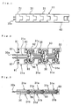
- Figs. 1 to 4 illustrate an electronic apparatus in accordance with Embodiment 1 of the present invention.
- a band 11 comprises a metallic end piece 21, a plurality of piece members 31 which are connected to each other to form a base, and a sensor box 40 attached to the side of the band opposite to the end piece 21.
- the band 11 contains a pair of conductive wires 30 as conductive members which are lead wires each of which is coated with an insulator such as a synthetic resin.
- the end of each of the conductive wires 30 has a ring groove which is formed by circumferentially melting the insulating coating, for example, using a heated trowel, the tip of each of the wires without the insulating coating being fixed by solder.
- the end piece 21 comprises end piece plates 21a and 21b, and each of the piece members 31 comprises piece plates 31a and 31b.
- the end piece plate 21a are formed threaded holes 91 for mounting a case, and threaded holes 92 for fixing the end piece plates, as illustrated in Fig. 2.
- the end piece plate 21b are formed through holes corresponding to the threaded holes 91, and through holes with counterbores (not shown) at positions corresponding to the threaded holes 92.
- Each of the end piece plates 21a and 21b is provided with recessed portions 21c for containing the conductive wires 30 and pipes 50 which will be described below.
- Each of the piece plates 31a has three threaded holes 93, and through holes (not shown) formed at positions corresponding to the threaded holes 93 of each of the piece plates 31b.
- Each of the piece plates 31a and 31b also has recessed portions 31c and 31d for containing the conductive wires 30 and the pipes 50.
- the metallic pipes 50 are contained between the end piece 21 and the piece member 31 and between the respective adjacent piece members 31 so as to be oriented in the direction crossing at right angles the direction of extension of the band 11, the conductive wires 30 being passed through the pipes 50.
- Each of the conductive wires 30 is extended while snaking and passing through the pipes 50 in the band, and conductively connected to a sensor contained in the sensor box 40.
- the pipes 50 are rotatably held between the end piece 21 and the piece members 31 so as to rotatably connect the end piece and the piece member 31 and connect the respective adjacent piece members 31.
- the band 11 is assembled as described below. After the end piece plate 21a, a required number of piece plates 31a and the sensor box 40 are arranged in a plane, the terminal portions of the conductive wires 30 passed through a required number of pipes 50 are respectively set in the recessed portions 21c of the end piece plate 21a. The pipes 50 through which the conductive wires 30 are respectively passed are arranged in the connection portion between the end piece plate 21a and the piece plate 31a, and the end piece plates 21a and 21b are screwed.
- the conductive wires 30 are then set in the recessed portions 31c of each of the piece plates 31a, the pipes 50 through which the conductive wires are respectively passed are arranged in the connection portion between the adjacent piece plates 31a, and the piece plates 31a and 31b are then screwed. The other piece plates are successively screwed in the same way as that described above. Finally, packings (not shown) are set to the other ends of the conductive wires 30, which have the same shape as that of the ends 30a, and the conductive wires 30 are forced into the conducting holes formed in the sensor box 40 together with the packings.
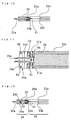
- the wrist watch case comprises a case band 60 and a case back 70, the case band 60 having conducting holes formed in a side thereof so as to contain the ends 30a of the conductive wires 30.
- the lower side of the case band 60 is provided with a groove for containing the packing 84 therein and threaded holes (not shown) for mounting the case back 70.
- the case back 70 has through holes (not shown) for screwing the case back 70 to the case band 60, and through holes (not shown) for mounting the end piece 21.
- the case back 70 is formed at the bottom of the case band 60 so as to partly project from the case band 60 in the directions of 12 o'clock and 6 o'clock of the watch.
- the band is mounted on the wrist watch case by forcing the ends 30a of the conductive wires 30, which project from the end piece 21, into the conducting holes of the case band 60 together with the packings 81 and then fixing the end piece 21 and the case back 70 by screws 80.
- the conductive wires 30 passed through the end piece 21 are preferably pressed by the recessed portions 21c for containing the wires 30 or bonded to the insides of the recessed portions 21c so as to be held in the direction of extension thereof. Since the conductive wires 30 are held in the end piece 21, the ends 30a of the conductive wires 30 introduced into the case band 60 are fixed to the case band 60 even if the band is deformed, thereby ensuring durability of the connection portion of the conductive wires 30.
- the band 11 is mounted on each of the sides of 12 o'clock and 6 o'clock of the wrist watch case, one of the bands is the above band 11 containing the conductive members, and the other band formed as an ordinary band can be provided with a band length adjusting mechanism, for example, using a hair pin or the like.
- a known free adjustment type generally used for wrist watch bands may be used.
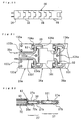
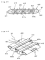
- FIGs. 5 to 7 illustrate Embodiment 2 of the present invention.
- An end piece 22 comprises end piece plate 22a and 22b, the end piece plate 22a having threaded holes 94 corresponding to the through holes (not shown) formed in the end piece plate 22b.
- the end piece plate 22a also has the same recessed portions 22c as those of Embodiment 1, which are formed in the direction of extension of the conductive wires 30 so as to contain the wires 30, and a groove 22d formed at right angles to the recessed portions 22C.
- the end piece plate 22b has the groove 22e formed for containing a spring bar 42.
- the groove 22e is formed for containing the spring bar 42
- the groove 22d is formed for containing the curved portions of the conductive wires 30, which are formed by bypassing the spring bar.
- the end piece 22 is connected to a piece member 32 comprising piece plates 32a and 32b, as described above.
- the piece plate 32a has the same structure as that of the piece plate 31a of Embodiment 1 in which threaded holes 95 corresponding to through holes (not shown formed in the piece plate 32b, which is the same as the piece 31b, are formed and includes recessed portions 32c corresponding to the recessed portions 31c containing the conductive wires 30.
- the wrist watch case comprises a case band 61 and a case back 71, conducting holes for introducing the conductive wires 30 being formed in a side of the case band 61, and the lower surface of the case band 61 has a groove formed for containing a waterproof packing 84.
- the case band 61 has joggle grooves (not shown) formed on the inner side of the case band 61 so as to engage the joggles (not shown) formed on the case back 71, the joggles being fitted in the joggle grooves.
- the band is mounted on the wrist watch case by the method described below.
- the end piece 22 of the band which is assembled by the same method as that in Embodiment 1 except that the spring bar 42 contained in the groove 22e of the end piece plate 22b is held in a "horn" 61a (not shown) of the case band 61 by pushing the ends of the spring bar 42, and is moved along the direction of projection of the "horn” 61a.
- Packings 82 are then set at the ends 30a of the conductive wires 30 which project from the end surface of the end piece 22.
- the ends 30a to which the packings 82 are set and forced into the conducting holes of the case band 61, and the ends of the spring bar 42 are then engaged the "horn holes" of the "horn” 61a.
- the end piece 22 has dimensions which can prevent as much as possible looseness between the side of the case band 61 and the spring bar 42, and that the rotation of the end piece 22 caused by rotation of the band is restricted as much as possible by bringing the upper portion of the end piece plate 22a and the lower portion of the end plate 22b in the direction of thickness of the band into contact with the side of the case band 61.
- Embodiment 3 relates to a band 13 made of a material such as natural leather, artificial leather or a synthetic resin.
- the band 13 has a metallic or non-metallic end piece 23 comprising end piece plates 23a and 23b, and a base 33 made of a material such as natural leather, artificial leather or a synthetic resin and comprising a surface member 33a and a rear member 33b, and a buckle 43.
- each of the end piece plates 23a and 23b are formed recessed portions 23c for containing the conductive wires 30 and pipes 51.
- the end piece plate 23a is provided with threaded holes 96 for mounting on a wrist watch case and threaded holes 97 for fixing the end piece plates
- the end piece plate 23b is provided with through holes corresponding to the threaded holes 96 and through holes with counterbores (not shown) corresponding to the threaded holes 97.
- Each of the surface member 33a and the rear member 33b which form the base 33 is made of a resin, e.g., urethane rubber, and recessed portions 33c for containing the conductive wires 30 and the pipes 51 and a recessed portion for containing a sensor unit (not shown) are formed in molding the base 33.
- the base 33 is formed by setting the pipes 51 through which the conductive wires are passed, the conductive wires 30 and the sensor (not shown) in a molded product of the rear member 33b, and then bonding the surface member 33a to the rear member 33b.
- the pipes 51 and the conductive wires 30 which project from the base 33 are then arranged in the end piece plate 23a, and the end piece plates 23a and 23b are screwed.
- the buckle 43 is attached at the time of bonding the surface member 33a to the rear member 33b.
- the pipes 51 are respectively extended to partions near the widthwise ends of the base 33 so as to sufficiently resist the loads applied to the band, such as twisting moment, tensile force and so on.
- the pipes 51 have notches 51a which are formed on the side opposite to the end piece so as to bend the conductive wires 30 at the notches 51a and dispose the wires 30 in the base 33. This can increase the strength of connection between the end piece 23 and the base 33 and maintain the shape of the connecting portion of the base 33.
- the end piece 23 may be made of either a metallic or non-metallic material.
- the recessed portions 23c and the recessed portions 22c of Embodiment 2 have the same size as that of the recessed portions 21c of Embodiment 1.
- the length of the band is adjusted by selecting a hole formed in another base which engages the buckle 43, as in normal cases.
- Figs. 11 and 12 illustrate Embodiment 4 of the present invention.
- Embodiment 4 is provided with the same base 33 as that of Embodiment 3, Embodiment 4 different from Embodiment 3 in a structure in which a spring bar 42 is passed through an end piece 24.
- the end piece 24 comprises end piece plates 24a and 24b, and the end piece plate 24a has fixing threaded holes 98 which correspond to the through holes (not shown) formed in the end piece plate 24b.
- the end piece plate 24a is also provided with recessed portions 24c for the conductive wires 30, and a groove 24d for containing the carved portions of the conductive wires 30, and the end piece plate 24b is provided with a groove 24e for containing the spring bar 42.
- the structures of other recessed portions for containing the conductive wires, the method of assembling the band and the method of mounting the band on the case are the same as in Embodiment 1 or 3.
- each of the above embodiments relates to the band structure and band mounting structure of, as an example, an electronic wrist watch having a band containing a sensor for measuring the blood pressure, the pulse or the bodily temperature
- the present invention is not limited to this sensor.
- the present invention can be applied to any apparatus having a band containing a conductive member, such as a band where conductive wires are disposed in the band for containing a communication antenna or secondary batter, which will be described below, in the band.
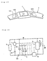
- this embodiment relates to an electronic wrist watch roughly comprising a watch case 1 containing a watch driving device, a generating device and a secondary battery, and a band 2 comprising leather, a resin or a plurality of metallic piece members which are connected to each other.
- secondary batteries 101 and 102 are contained in the band 2 near the watch case, and connected to the watch case by conductive wires 103.
- batteries can be used as the secondary batteries 101 and 102, electric double layer capacitors are preferred from the viewpoint of the allowable number of times of charging and discharging, and polyacene lithium capacitors are preferred from the viewpoints of voltage recovery properties and energy density.
- a single secondary battery may be provided, or any desired number of batteries may be provided according to demand.
- Fig. 14 illustrates the circuit of an electric power supply system of this embodiment.
- a rotor In a generating device G, a rotor is rotated by the torque of a oscillating weight to generate electromotive force in an electromagnetic coil to obtain output current, as described below.
- a limiter circuit L and a reverse current preventing diode D1 are connected in parallel to the generating device G.
- the limiter circuit L is a circuit for preventing overcharging of the secondary batteries.
- a rectifying diode D2 performs half-wave rectification of the AC current generated in the electromagnetic coil and prevents reverse current.
- a large-capacity capacitor SC which is connected in parallel to the generating device G and the limiter circuit L, is a secondary battery contained in the watch case so as to store the electric power generated by the generating device G.
- a control driving circuit P comprises an integrated circuit for driving a driving motor (or a display) R for the watch and controlling the limiter circuit L and a booster circuit B and a selective switching circuit SW, both of which will be described below.
- Reference character CB denotes a backup capacitor for the control driving circuit P.
- An internal band portion T is a portion contained in the band 2 shown in Fig. 13 and comprising internal band capacitors C1 and C2 serving as auxiliary secondary batteries and connected in parallel to the large-capacity capacitor SC contained in the watch case.
- the booster circuit B is a circuit for boosting the electric power generated by the generating circuit G and stored in each of the secondary batteries to the working voltage of the control driving circuit P. Since the output voltage of the capacitor as each of the secondary batteries significantly changes with the charging amount, the voltage on the side of the control driving circuit P and the backup capacitor CB is increased by, for example, 2 or 3 times, in accordance with the output voltage of the capacitor in order to constantly maintain the operation of the control driving circuit P. Typical examples of the configuration of the circuit are disclosed in Japanese Patent Laid-Open Nos. 60-203887 and 61-124887.
- This embodiment is practical in that the storage capacity can be increased by a simple circuit configuration, and can be applied to the configuration of an internal circuit of an ordinary watch case without any change.
- a circuit configuration for ensuring a driving voltage by the booster circuit B is indispensable.
- Fig. 15 illustrates a configuration in which the internal band portion T can be connected and cut off by the selective switching circuit SW.
- the selective switching circuit SW selectively changes the connection state between the circuit part of the watch case and the internal band portion T on the basis of command from the control driving circuit P.
- a simple opening/closing switch which operates by a control signal from the control driving circuit P or a circuit which opens and closes on the basis of the voltage or current detected by itself may be used as the selective switching circuit.
- the selective switching circuit SW is generally provided in the IC of the watch case, it can comprises another IC so as to be provided in the band.
- the control driving circuit P when the large-capacity capacitor SC is charged, the control driving circuit P outputs a closing signal to the selective switching circuit SW in order to prevent overcharging to connect the band internal T to the case circuit.
- the synthetic capacity is increased by connection of the band internal capacitors C1 and C2, thereby preventing overcharging and further charging the capacitor.
- an opening signal is transmitted to the selective switching circuit SW so that the band internal capacitors C1 and C2 are cut off.
- the charging current is detected, and particularly, the charging current at the start of charging is limited to a predetermined value or less to prevent a voltage drop on the case side and prevent consumption of electric power by opening the circuit, for example, when an accident such as short-circuit of the internal band capacitors or band internal wiring occurs.
- an alarm can be given by a display or a sound generator provided on the side of the watch case.
- the auxiliary secondary batteries are cut off by the selective switching circuit for intermitting connection between the band internal T and the circuit portion of the case so that the voltage can be maintained by decreasing the capacity of the secondary batteries.
- the capacity of the secondary batteries is increased by connecting the auxiliary secondary batteries in the band so that the generated electric power can be stored, not discarded. It is also possible to prevent a voltage drop on the case side by cutting off the selective switching circuit during charging, and automatically avoid stop of the function of the watch case by cutting off the selective switching circuit when an accident such as short-circuit occurs in the band.
- the characteristics of this embodiment apply to the modified embodiment shown in Fig. 16.
- the modified embodiment is different from the above embodiment only in the point that selective switching circuits S1 and S2 are connected in series to the corresponding band internal capacitors C1 and C2, respectively, of the band internal T.
- Each of the selective switching circuits S1 an S2 has the same function as that of the selective switching circuit SW, and is generally provided in the IC of the watch case.
- Each of the selective switching circuits S1 and S2 may of course be contained as another IC in the band.
- the modified embodiment improves controllability, particularly, when many auxiliary secondary batteries are disposed in the band, or when each of auxiliary secondary batteries has a large capacity.
- the embodiment is effective in that the voltage on the case side can be maintained by adjusting the capacity of each of the auxiliary secondary batteries, and that only an auxiliary secondary battery of a plurality of auxiliary secondary batteries, which produces an accident, can be cut off.
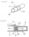
- Fig. 17 illustrates another modified embodiment in which a generating device 111 similar to the generating device G shown in Figs. 14 and 15 is contained together with a secondary battery 104 in the same band 2 as that of the electronic wrist watch shown in Fig. 13.
- the generating device 111 and the secondary battery 104 are connected to each other by conductive wires 112, and the secondary battery 104 and the watch case are connected to each other by conductive wires 105.
- conductive wires 112 As illustrated in Fig.
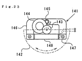
- the generating device 111 comprises a oscillating weight 142 having an eccentric weight distribution, a rotor 145 connected to the oscillating weight 142 through a speed-up gear trains 143 and 144 and magnetized in the rotational direction, a U-shaped plate stator 146 containing the rotor 145 in the through hole thereof, coil core 147 respectively screwed to both ends of the stator 146, and an electromagnetic coil 148 wound around the coil core 147.
- the secondary battery 104 and the generating device 111 are contained in a space provided in the band. When the band itself is made of a conductor, each of the secondary battery 104 and the generating device 111 is contained in an insulating case and disposed in the band.
- Figs. 18 to 22 illustrate the structure of a band suitable for a case where the secondary battery of the above embodiments is contained in the band.
- the band 15 shown in Fig. 18 roughly comprises an end piece 25 which is connected to the watch case and preferably made of a metallic material, and a base 35 which is rotatably connected to the end piece 25, forming a principal portion of the band, and preferably made of leather or synthetic resin.
- the end piece 25 comprises end piece plates 25a and 25b (not shown), and the base 35 comprises a surface member 35a and a rear member 35b (not shown).
- the end piece plate 25a has threaded holes 123a and 123d for fixing to the case, and threaded holes 123b, 123c and 123e for fixing to the end piece plate 25b.
- the end piece plate 25a also has recessed portions 123f for containing the conductive wires 30 and pipes 52.
- the end piece plate 25b has through holes (not shown) and counterbores (for preventing the top of a fastening bolt from projecting from the bottom of the end piece plate 25b, not shown) at positions corresponding to the threaded holes 123b, 123c and 123e of the end piece plate 25a.
- the end piece plate 25b also has the recessed portions formed on the upper side thereof, which are the same as the recessed portions 123f of the end piece plate 25a.
- Each of the conductive wires 30 comprises a lead wire coated with an insulating resin, and has a ring groove formed in the periphery of the insulating coating at the end 30a connected to the watch case in order to engage a packing of the connection portion, the insulating coating at the tip thereof being removed.
- the connecting pipes 52 are rotatably fined in the recessed portions of the end piece 25, and fixed and bonded between the front member 35a and the rear member 35b of the base 35, the conductive wires 30 being respectively passed through the pipes 52.
- the pipes are extended to the side edges of the base 35 in order to connect and reliably support the connection portion of the base 35.
- a notch portion 52a is formed on the side of each pipe 52 opposite to the end of the pieces 25 so that the conductive wires 30 are introduced into the base 35 from the notched portions 52a.
- the conductive wires 30 and the secondary battery 101 are held and bonded.
- a selective switching circuit or opening/closing switch may be contained in a secondary battery 101, or exclusive selective switching circuit may be contained independently in the base. These circuits may of course be contained in the watch case.
- the connecting pipes 52 rotatably connect the end piece 25 and the base 35, and fix the conductive wires 30 in the end piece 25 in the direction of extension thereof so as to prevent application of loads to the ends 30a connected to the watch case.
- the notches 52a permit the conductive wires 30 to slightly move in the direction of extension thereof within the base 35.
- Fig. 20 illustrate en embodiment in which a band 16 has a base comprising a plurality of metallic piece members 36 connected to each other. Since an end piece 26 is the same as the end piece 25, description of the end piece 26 is omitted.
- Each of the piece members 36 comprises piece plates 36a and 36b (not shown), the piece plate 36a has threaded holes 134a, 134b and 134c for fixing to the piece plate 36b, as shown in Fig. 21.
- Recessed portions 134d for containing the conductive wires 30 and pipes 53, and a recessed portion 134e for containing the secondary battery 101 are also formed on each of the piece plates 36a. Similarly, these recessed portions are formed on each of the piece plates 36b.
- Each of the piece plates 36b has through holes (not shown) and counterbores (for preventing the top of a fastening bolt from projecting from the bottom of the rear member 36b (not shown) at positions corresponding to the threaded holes 134a, 134b and 134c of each of the piece plates 36a.
- the cylindrical pipes 53 rotatably engage the recessed portions of the end piece and the piece member to rotatably connect the both.
- the secondary battery 101 is contained an insulating case or contained in the recessed portion 134e to which an insulating sheet is applied.
- Fig. 22 illustrate a connection portion between an end piece 27 which forms a band and a case band 62 of the watch case.
- the band comprises the end piece 27 and a plurality of piece members 37 connected to each other. Since the band is substantially the same as that shown in Fig. 19, description thereof is omitted.
- a side of the case band 62 is provided with conducting holes for introducing the ends 30a of the conductive wires in the connection portion between the end piece 27 and the case nand 62.
- the wires 30 are inserted into the conducting holes, and the ends thereof are connected to connecting terminals in the watch case and fixed in the state where each of the packings 83 is engaged a ring groove.
- a case back 72 of the watch case has a supporting portion 72a sidewardly extended so that the end piece 27 is disposed on the supporting portion 72a and screwed thereto.
- the structure for mounting end piece is not limited to the above fixed structure, the end piece may be indirectly connected through a spring bar.
- the base is rotatably connected to the end piece which is connected to the watch case, and the pipes through which the conductive wires are passed are arranged in parallel to the rotation axis, thereby preventing application of loads to connection points of the conductive wires on the case side and connection points thereof on the side of the secondary battery without interfering with the fitting properties of the band.
- the pipes are used as connecting shafts, the number of parts is decreased, and the assembly becomes easy.
- the present invention is applied to an electronic wrist watch
- the present invention can be applied to any electronic apparatus having a fixing band for fitting to an arm or another part of the human body and having the function as an electronic sphygmomanometer, a communication device or an electronic pocket notebook.
- a solar cell and other known generating mechanisms may of course be used as the generating device.
- Figs. 24 and 25 are drawings illustrating Embodiment 6.
- the insulating surrounding member 150 shown in Fig. 24 is made of an insulating high-molecular material having elasticity, such as IIR (butyl rubber) or NBR (acrylonitrile butadiene rubber).
- the insulating surrounding member 150 is formed as a hollow shape having a through hole portion 150a.
- the insulating surrounding member 150 is used in a state where it covers the periphery of a conductive terminal member 155.
- the conductive terminal member 155 is preferably contained in a mold for forming the insulating surrounding member 150 by insert molding.
- the insulating surrounding member 150 may be formed so that a single conductor is passed therethrough, as shown in the drawing, or a plurality of conductors are covered. In this case, it is preferable for maintaining insulating properties between respective conductors that a plurality of conductors are burned in an insulating resin which is contained in the insulting surrounding member 150.
- Fig. 25 illustrates an embodiment in which the insulating surrounding member 150 and the conductive terminal member 155 are used for connecting a case band 63 of a wrist watch and an end piece 28.
- the case band 63 of the wrist watch is fixed to a case back 73 by screws 85
- the end piece 28 is fixed to the case back 73 by screws 86a and 86b.
- the opposite sides of the case band 63 and end piece 28 which are adjacent to each other have respectively conducting holes formed at opposite positions so that the conductive terminal member 155 provided with the insulating surrounding member 150 is forced into each of the conducting holes.
- the insulating surrounding member 150 is provided with projecting seal portions 151 and 152 which are formed in a ring, as shown in Fig. 24. The projecting seal portions are respectively forced into the conducting holes of the case band 63 and the end piece 28 to seal between the insulating surrounding member 150 and both conducting holes.
- the insulating surrounding member 150 functions as a waterproof packing and an insulating member between conductive members and between the conductive members and the watch case or the band. Since the position between the insulating coating and the packing is previously defined, the assembly is easy, and the production cost can thus be decreased. Since sweat or water does not adhere directly to the conductive terminal member 155, corrosion resistance need not taken into consideration, and the material for the conductive terminal member 155 can be selected on the basis of electrical characteristics alone. In addition, since there is no need to provide another sealing member onto the insulating coating, the diameter of the terminal portion can be decreased, therefore an attempt can be made to thin the case band 63.
- the conductive terminal members 155 When a battery is contained in the end piece 28, the conductive terminal members 155 are connected directly to the electrode or a connecting fitment. When the conductive wires 30 the same as that used in each of the above embodiments are disposed in the band, the conductive terminal member 155 may be connected to each of the conductive wires 30 by solder or the like in the end piece 28, or each of the conductive wires 30 may be passed through the insulating surrounding member 150 in place of the conductive terminal member 155.
- the end piece 28 may be connected rotatable with respect to the case band 63 by using such as a spring bar.
- the insulating surrounding member 150 must be made of a material with sufficient elasticity or flexibility so that it can follow the rotational displacement of the end piece 28.
- a bent portion comprising such as a hinge structure is preferably provided on the conductive terminal members and the conductive wires so as to follow the rotation of the end piece, and a slide structure is provided for absorbing a displacement in the direction of extension of the conductive member caused by the rotation of the end piece.
- Fig. 26 illustrates a structure in accordance with Embodiment 7 of the present invention.
- a case band 64 of a wrist watch and an end piece 29 are connected and fixed to each other by screws 85 and 86 through a case back 74.
- Both ends of a conductive wire 30 are respectively inserted into conductive terminal members 156 and 157, and coated with enlarged-diameter portions 161 and 162 formed at both ends of the insulating surrounding member 160.
- the enlarged-diameter portions 161 and 162 have projecting seal portions 163 and 164, respectively, integrally formed thereon.
- the insulating surrounding member 160 is continuously formed so as to completely coat each of the conductive wires 30 between the enlarged-diameter portions 161 and 162.
- each of the conductive wires 30 coated with the insulating surrounding members 160 are forced into conducting holes formed in the side of the case band 64 and conducting holes formed in a piece member 39 among the constitutive piece members of the band base, which contains a battery, a sensor and so on.
- the end of each of the conductive wires 30 which projects from the tip of the conductive terminal member 156 is brought into pressure contact with an elastic terminal piece 64b connected to the circuit substrate 64a provided in the case band 64.
- Fig. 27 illustrates a modified embodiment of the above embodiment.
- an insulating surrounding member 168 has an inner diameter greater than the outer diameter of the conductive wire 30 and a gap between the conductive wire 30 and the insulating surrounding member 168.
- Each of the insulating surrounding members 168 has a projecting seal portion 166 formed at an end 165 thereof, which is inserted into a conducting hole formed in the side of the watch case band 64.
- the end 165 is held between the inner surface of the conducting hole and a cylindrical fitting member 167 which is forced into the hole from the inside of the case band 64, and secured to the case band 64.
- the fitting member 167 preferably comprises an insulator for preventing poor insulation.
- each of the insulating surrounding members 168 is made of a material having flexibility, and the end piece 29' is rotatably provided on the watch case band 64 by horns 65. When the end piece 29' is rotated, therefore, the insulating surrounding members 168 are deformed in accordance with the direction of movement. In this case, since a gap is present between the conductive wire 30 contained in each of the insulating surrounding members 168 and the insulating surrounding member 168 around the circumference of each of the wires 30, the stress caused by deformation of the insulating surrounding member 168 is decreased.
- the fitting member 167 securely fixes the end 165 of the insulating surrounding member 168, and supports the conductive wire 30 passed therethrough for a predetermined length for preventing bending thereof.
- the lengthwise displacement caused by bending of the conductive wire 30 is absorbed by the elasticity of the elastic terminal piece 64b.
- a hinge structure which permits bending of the conductive wire 30 is provided in the vicinity of the rotational axis of the end piece 29', or a slide structure is provided so as to be slidably overlapped on a portion of the conductive wire 30, whereby absorbing the lengthwise displacement of the conductive wire 30 and canceling stress to bend the conductive wire 30.
- each of the wiring structures shown in Figs. 26 and 27 is suitable for disposing in the band shown in each of Embodiments 1 to 4.
- the insulating surrounding member 160 shown in Fig. 26 is preferably produced by insert molding, as shown in Fig. 28.
- the conductive wire 30 is previously fitted into the conductive terminal members 156 and 157, and then fixed by brazing, welding or caulking.
- Ring grooves 156a and 157a are formed on the surfaces of the conductive terminal members 156 and 157, respectively, and ring recessed portions a and b corresponding to the ring grooves 156a and 157a, respectively, are formed on the cavities of molds A and B.
- a synthetic resin material having elasticity which is the same as that used in Embodiment 6 is injected into the molds and then solidified to form the insulating surrounding member 160 shown in Fig. 26.
- the wiring and terminal portion are coated with the integral insulating surrounding member, the insulation work need not carried out for the terminal portions (or the connecting portion) of the conductive wires 30 during assembly, and the production cost can thus be decreased. Since the projecting seal portion is integrally formed, sufficient waterproofness and insulating properties can securely be provided, and the diameter of the connecting portion can be decreased, thereby permitting an attempt to thin the case band 64.
- each of the pipes preferably comprises a roll-formed plate made of a shape-memory-alloy and having an opening, and is previously treated so that the opening opens in a high temperature phase, and closes in a low temperature phase.
- the wire may be inserted into the opening which is enlarged by heating, and then disposed in the band with the opening closed by cooling.
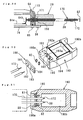
- Fig. 29 illustrates Embodiment 8 of the present invention.
- an insulating surrounding member 170 having the same end structure as that in Embodiment 7 is connected between the case band 64 and the end piece 29.
- the same portions as those in Embodiment 7 are denoted by the same reference numerals, and are not described below.
- the other ends 172 of the insulating surrounding member 170 are terminated in the state where they cover the peripheries of the conductive wires 30, as shown in Fig. 29. As illustrated in Fig.
- the ends are respectively passed through through holes 182 and 183 of a mounting plate 180, through packings 82 as seal members and then inserted into the conducting holes 192 and 193 which are formed in a housing member 190 for a sensor or battery to be contained in the band.
- the mounting plate 180 has fixing holes 181 and 184 through which screws 87 and 88 are respectively screwed into threaded holes 191 and 192 of the housing member 190 so that the conductive wires 30 are fixed to the housing member 190, as shown in Fig. 31.
- the conducting holes 192 and 193 of the housing member 190 have the recessed portions 192a and 193b, respectively, formed at the opening verges thereof for receiving the packings 82.
- the packings 82 which are received in the recessed portions 192a and 193a are held under pressure in narrow portions between the mounting plate 180 and the housing member 190 so as to tightly hold the conductive wires 30 by the deformation caused by pressure.
- the housing member 190 has a recessed portion 190a formed on the side of mounting of the conductive wires 30 so that the mounting plate 180 can be received therein, the recessed portion 190a communicating with a recessed housing portion 190b through the conducting holes 192 and 193.
- An electronic function part such as a sensor or battery is contained in the recessed housing portion 190b.
- a cover member (not shown) is mounted on the upper side of the housing member 190 so as to close the recessed housing portion 190b.
- the cover member is mounted by a known method such as screwing or caulking, and the mounting structure between the cover member and the housing member may be any desired structure such as a structure for holding packing under pressure, or a step-formed structure for engaging both members.
- the housing member 190 may be disposed in a piece member of the band, or the housing member 190 itself may form a piece member of the band or a fastener (buckle) of the band.
- the conductive wires 30 coated with the insulating surrounding members 170 can be inserted into the band after the band structure is completed, thereby facilitating the production.
- the wiring connection to the electronic function part can also be securely performed.
- the conductive wires 30 are reliably fixed to the receiving member 190 by the mounting plate 180, whereby preventing application of a load to the connection points between the conductive wires 30 and the electronic function part.
- a band base comprises a plurality of piece members rotatably connected to each other.
- Embodiment 9 of the present invention which relates to a piece member.
- Embodiment 9 comprises an outer sheath member which forms an outer housing of a piece member, and an inner piece member which is rotatably contained in the outer sheath member and which has the function to connect adjacent outer sheath members.
- the outer sheath member and inner piece member may be made of any desired material such as a metallic or non-metallic material, but both members generally comprise a metallic plate material.
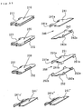
- Fig. 32 is a perspective view illustrating various examples of construction of inner piece members.
- Each of inner piece members 210, 220 and 230 is formed by bending a plate material by press working.
- the inner piece members 21, 220 and 230 have openings 211, 221 and 222, and 231 and 232, respectively, which are formed so as to permit conductive members to pass between plate portions formed by bending a plate material.
- the inner piece member 230 having curved end surfaces is most preferred in view of the fitness to the outer sheath member and rotational characteristics.
- Inner piece members 240 and 250 comprise two plate parts 241 and 242, and 251 and 252, respectively, the plate parts having projection portions 241a and 242a, 251a and 251b. and 252a and 252b, respectively, which are projected in a hook-like form, and which respectively contact the surfaces of the other opposite plate parts to secure the openings and spaces for passing the conductive members therethrough.
- the design of each of the plate parts can easily be changed, for example, uneven portions 241c' and 241c'' can be formed on plate parts 241' and 241'', respectively.
- Fig. 33 illustrates a base structure comprising combination of the above inner piece member 220 and an outer sheath member 310 which can contains the inner piece member 220.
- the outer sheath member 310 is formed by bending a plate material in a square cylinder, and has openings 311 and 312 on the front and rear sides thereof, and open cover portions 313 and 314 on the right and left sides thereof.
- the inner piece member 220 is inserted into the outer sheath member 310 from the open cover portion 313 or 314 so that the rear end having the opening 221 is exposed to the outside from the opening 311. At this time, the inner piece member 220 cannot be removed from the opening 311 due to differences in the width.
- FIG. 34 Another inner piece member 220 is inserted into an adjacent outer sheath member, and the rear end of the other inner piece member 220 which projects from the opening 311 is introduced into the outer sheath member 310 from the front opening 312.
- connecting members 320 are respectively inserted and forced into the right and left open cover portions 313 and 314 to insert, with plays, projecting shafts 321 and 322 of the connecting members 320 between the upper and lower plate parts of the inner piece members 220.
- the outer sheath members 310 are connected to each other through the inner piece members 220, as shown in Fig. 34.
- the band is subjected to barrel polishing to form a mirror surface and washed, and then only the surfaces of the outer sheath members are subjected to, for example, satin finish, to form by a method without a masking work a good design in which the satin finish on the surfaces of the outer sheath members are clearly symmetrical with the mirror surfaces of the inner piece members in recessed portions.
- This band structure is suitable for the present invention in the point that the conductive members can be inserted after assembly.
- wiring can easily be performed by inserting the conductive wires 30 into the openings.
- the angle of rotation between respective piece members can be set on the basis of the relation between the thickness of the inner piece members and the height of the housing inner space of each of the outer sheath members. Namely, the rotation of respective adjacent piece members with bending of the band is limited to an angle where the front and rear ends of an inner piece member contact the upper and lower surfaces of the inside of an outer sheath member. Thus a local large bending angle is not produced in the band, and the deformation fatigue of the conductive members passed through the band can be decreased.
- the ratio between the thickness of an inner piece member and the thickness of an outer sheath member is preferably appropriately set in consideration of a balance of fitting properties, flexibility of the conductive members, and durability.
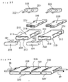
- Fig. 35 illustrates a band structure which uses the inner piece member 240, the outer sheath members 310 and the connecting members 320 being the same as those shown in Fig. 33.
- the assembly method is also the same as that shown in Fig. 33 except that two plate parts 241' and 242 are contained in each of the outer sheath members 310.
- the appearance of the inner piece members which are respectively partly exposed from the outer sheath members 310 can be changed by the irregular portion 241c' formed on the plate parts 241'.
- the recessed portions of the exposed inner piece members which are formed between the respective outer sheath members 310 shown in Fig. 34 can be made plane, as shown in Fig. 36.
- each of the openings 311 and 312 of the outer sheath members 310 shown in Figs. 33 and 35 is not limited to a straight line as shown in the drawings, and the opening verge can easily be formed in various forms such as a wave-like form, an irregular form and so on.
- the appearance can be made varied, and the change in only the shape of the opening verge is advantageous for suppressing an increase in cost.
- Fig. 37 illustrates a band structure comprising combination of the inner piece members 210 and the outer sheath members 330.
- Each of the outer sheath members 330 is provided with a rear opening 331, and a front opening 333 which is formed in the front side of a front receiving portion 332 forwardly projected.
- the inner piece members 210 are respectively inserted into the outer sheath members 330 from an open cover portion 334 or 335, and the verge of the opening 211 is forwardly drawn out from the opening 333 of each of the outer sheath members 330.
- the verge of the opening 211 is introduced into the opening 331 of the adjacent outer sheath member 330 and engaged a projecting shaft 322 of each of the connecting members 320.
- the front receiving portions 332 are respectively combined with the openings 331 of the adjacent outer sheath members 330 to connect the outer sheath members to each other.
- the inner piece members 210 are respectively interposed between the verges of the openings 333 and the conductive members 30 passed therethrough, the verges do not contact directly the conductive members 30. If each of the verges of the openings 333 has a sharp form, no problem occurs, and the openings can be formed by cutting.
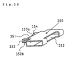
- the functions of the inner piece members 210 and the outer piece members 330 shown in Figs. 37 and 38 are realized by a single member.
- the piece member 350 has tongue-like portions 350a and 350b which rearwardly project and between which an opening 351 is provided, a pair of projections 353 and 354 being formed on the left and right sides of the tongue-like portion 350a.
- the verge of the opening 351 is introduced into an adjacent piece member 350 from a front opening 352 thereof, and engaged the projecting shaft 322 of the connecting member 320 shown in Figs. 37 and 38.
- This structure permits the easy assembly work using a single piece member, and an attempt to decrease the assembly cost.
- this embodiment relates to the case where two conductive members are passed through the band, one conductive member or at least three conductive members may be passed through the band, and a conductive member comprising a laminated foil or a flexible sheet (substrate) in which a wiring pattern is formed on a resin base may be passed through the band.
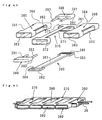
- Fig. 40 illustrates Embodiment 10 of the present invention.
- the Embodiment 10 has a band structure in which respective piece members 360 are connected to each other through connecting members 370.
- Each of the piece members 360 has the form of a square cylinder which is substantially the same as that of the outer sheath members or the piece members of the above Embodiment 9, and is provided with front and rear openings 361 and 362 and open cover portions 363 and 364 on the left and right sides thereof.
- each of the connecting member 370 has, at the center thereof, a bridge-like portion 371 having a length which is substantially the same as the width of the piece members 360, and square cylinder-formed portions 372 and 373 at both ends of the bridge-like portion 371.
- An engaging member 380 having a bridge-like portion 381 and engaging plates 382 and 383 provided at both ends thereof is inserted into the connecting members 370, and a pair of piece members 360 are inserted between the square cylinder-formed portions 372 and 373 of connecting member 370 from the front and rear sides thereof. Since the engaging plates 382 and 383 of the engaging member 380 have engaging ribs 384 and 385, respectively, which are provided on the surfaces thereof, when connecting members 390 are respectively forced into the square cylinder-formed portions 372 and 373 of the connecting members 370, engaging grooves 393 respectively formed on the bottom of the connecting members 390 engage the engaging ribs 384 and 385 of the engaging member 380.
- projecting shafts 391 and 392 of the connecting member 390 engage each of the open cover portions 363 and 364 of the piece members 360 through the square cylinder-formed portions 372 and 373 of connecting member 370 to bring about a state where the piece members 360 and the connecting members 370 are alternately connected, as shown in Fig. 41.
- This band structure is the same as that of the above Embodiment 9 in the point that it comprises two types of members including the piece members 360 and the connecting members 370.
- the limit on the band design can further be decreased, as compared with Embodiment 9.
- Embodiment 10 as shown in Figs. 41 and 42, even if the distance between the piece members 360 is increased, the width of the bridge-like portions 371 can be adjusted so as not to expose the internal conductive wires, thereby facilitating design of the band. It is also apparent that the distance between the piece members 360 can easily be changed by changing the form of the connecting members 370.
- both members can integrally be formed, for example, another bridge-like form may be provided on the lower side of each of the connecting members 370.
- the connecting members 390 may respectively engage directly the square cylinder-formed portions 372 and 373 of each of the connecting members 370 in place of the engagement structure comprising the connecting members 390 and the engaging members 380.
- an irregular portion 360c' can be provided on an exposure surface, as in the piece member 360' shown in Fig. 43, and the design of the verge of each of the openings can variously be changed.
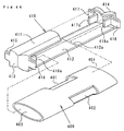
- Figs. 44 to 46 illustrate a structure in accordance with Embodiment 11 of the present invention.
- the Embodiment 11 relates to a band structure in which elliptic cylinder-formed piece members 400 are connected to each other through connecting members 410.
- Each of the piece members 400 has front and rear openings 401 and 402 for passing conductive members therethrough, and open cover portions 403 and 404 on the left and right sides thereof.
- Each of the connecting members 410 has a rectangular frame form comprising an upper frame 411, a lower frame 412 and left and right sides 413 and 414, engaging arms 415 and 416, and 417 and 418 being projected from the sides 413 and 414, respectively.
- the engaging arms 415, 416, 417 and 418 are extended forward or rearward, folded toward the base side and further bent to form engaging ends 415a (not shown), 416a, 417a and 418a, respectively, which are inwardly extended toward the center from the sides 413 and 414.
- each of the connecting members 410 is formed by folding a plate material in a rectangular form, as shown by the presence of a butt portion 412a of the lower frame 412 (Fig. 44).
- the piece members 400 and the connecting members 410 are combined by the method below, as shown in Fig. 45.
- the upper frame 411, the lower frame 412 and the sides 413 and 414 of each of the connecting members 410 are formed by folding.
- the piece members 400 are respectively brought into contact with the connecting members 410 before folding, and the engaging ends 415a (not shown), 416a, 417a and 418a are engaged the open cover portions 403 and 404 of the piece members 400 during formation of the upper frame 411 and the sides 413 and 414 by folding.
- the sides 413 and 414 and the lower frame 412 are finally formed by folding to close the piece members by the bun portions 412a.
- the band structure can comprise only two types of parts including the piece members and the connecting members, and thus has the effect of decreasing the production cost.
- each of the engaging arms has a bent form, the flexibility and elasticity can be adjusted by changing the bent form and the length, and it is possible to apply proper rotational resistance to the band or limit the angle of rotation between the respective piece members for protecting the conductive members passed through the band.
- the distance between adjacent engaging arms can be adjusted so as to create contact force between adjacent piece members by the elasticity of the engaging arms, or prevent contact between adjacent piece members when the band is stretched.
- each of the piece members and connecting members has a high flexibility.
- an irregular portion 400c can be provided on the upper side of each of the piece members 400, or a projecting edge 400d can be provided on the upper and lower portions of the open cover portion of each of the piece members 400, as shown by dotted lines in Fig. 46. This can be applied to the connecting members 410.
- Embodiment 12 comprising different conductive members is described with reference to Figs. 47 and 48.
- a conductive wire with an insulating coating shown in each of the above embodiments is generally used as a conductive member, particularly, when the durability of the conductive member is taken into account, there is the danger that the conductive member is cracked or cut due to the repeated stress caused by deformation of the band. It is thus preferable to use conductive wires 500 which are helically or wavily bent, as shown in Fig. 47.
- each of the conductive wires 500 is provided with elasticity in the direction of extension due to the helical or wavy form thereof, the conductive wires 500 can easily expand and contract in the direction of extension thereof and bend at the time of deformation of the band, the durability to the repeated deformation of the band can be increased.
- Each of the conductive wires 500 is contained in an insulating tube 510 for maintaining the form of the wires so as to permit the wires to follow deformation of the band, and prevent wearing or deflection of the helical or wavy form from occurring due to unnecessary contact in deformation of the band, and is connected to a conductive terminal member 520 exposed from the end of the insulating tube, as shown in Fig. 48.
- the conductive wires 500 are generally helically or wavily bent over the whole length thereof, the wires may be partly bent in the form. Particularly, only a portion subjected to large deformation, e.g.., portions passed through the pipes 50 shown in Fig. 47, may be helically bent. In this way, when only a portion of each of the conductive wires is bent, the production cost can be decreased, and the average diameter of a portion for containing the conductive wires 500 can be decreased, thereby thinning the band.
- an electronic apparatus comprises a fitting band containing conductive members, an end piece engaged a case, and a base rotatably connected to the end piece.
- the fitting properties are thus improved because the base rotates by its own weight when set on an arm.
- the conductive members are held by the end piece, but rotatably disposed with respect to the base, the stress applied to the connection portion between the case and the conductive members can be decreased even if the fitting band is deformed, and the stress applied to the internal conductive members and deformation thereof can also be decreased. It is thus possible to increase electrical durability, reliability and safety.
- the conductive members are not subjected to the deformation and load in the connection portion between the case and the fitting band, and thus durability of the conductive members can be ensured. Since the design of the portion mounted on the case can be freely determined to a "Roof-attached Horn style” structure, a structure “Tow Horn style” or a structure "without a horn", the limitations on design can be decreased.
- the hollow members are arranged along the rotation axis, even if the base is rotated, the deformation of the conductive members respectively passed through the hollow members can be suppressed, and positions of the conductive members in the direction of extension of the fitting band can be maintained. It is thus possible to increase the durability, reliability and safety of the conductive members without applying a local load or a large deformation thereto.
- each of the hollow members comprises a cylindrical connecting shaft so as to further have the function to position and support the conductive members and the rotatable connecting function, the connecting structure is simplified, the number of necessary parts is decreased, and the assembly becomes easy.
- the storage capacity can be increased without limiting the housing capacity, and excess electric power which cannot be stored in the secondary battery in the watch case can be stored in the auxiliary secondary battery, thereby increasing the operating time with no power generation, and significantly decreasing the opportunity that electric power is discarded for preventing overcharging, as compared with a conventional structure.
- the synthetic capacity of the secondary battery and the auxiliary secondary battery can be adjusted by an operating member such as an operating button or the like or control means of Claim 8 or 9 if required, and an accident such as disconnection or short-circuit and so on on the side of the auxiliary secondary battery can thus be coped with.
- the current limiting means can prevent a voltage drop on the side of the watch case during charging of the auxiliary secondary battery.
- the insulating surrounding member can reliably ensure the insulating properties in portions where the conductive members are passed through, and thus prevent the poor insulation caused by adhesion of sweat or water.
- the insulating surrounding members are fixed to the case with a gap between the insulating surrounding members and the conductive members, and is provided with flexibility, the conductive members are slightly stressed even if the insulating surrounding members are deformed by rotation of the fitting band, and it is thus possible to prevent the occurrence of poor insulation and disconnection of the conductive members.
- a projecting seal portion is integrally provided so that the insulating surrounding members ensure insulating properties and waterproofness in the portions where the conductive members are passed through, it is possible to prevent the poor insulation or deterioration in durability caused by corrosion with a liquid, and easily assemble the portions where the conductive wires are passed through.
- member's coating portion are respectively integrally provided on the insulating surrounding members so as to further function as an insulating coating for each of the conductive members in the direction of extension thereof.
- the ends of the conductive members can be securely connected to the electronic function member in the fitting band without increased-diameter portions at the ends, such as insulating surrounding members, sealing portions or terminals, the conductive members can be passed after the fitting band is produced, thereby facilitating the assembly work.
- the connecting portion between the piece members can be coated with a bridge-like portion, the distance between adjacent piece members can be freely changed with preventing exposure of the conductive members.
- engaging arms are integrally provided on a connecting member, the need to prepare other engaging members for connection can be eliminated, and thus an attempt can be made to decrease the number of parts.
- the conductive members are formed so that it can expand and contract in the direction of extension thereof, and an insulating coating is provided on each of the conductive members without interfering with expansion and contraction, it is possible to prevent damage of the conductive members, such as crack or cutting, which is caused by deformation of the fitting band, and thus improve the durability of the conductive members.
Description
Claims (24)
- An electronic apparatus with a fitting band, comprising a case (1) and a fitting band (2, 11) containing conductive members (30) therein; wherein said fitting band comprises an end piece (21 to 24) for engaging said case, and abase (33) connected to said end piece so as to be rotatable in the direction of bending of said fitting band during fastening, characterised in that said conductive members:are contained in a state where they are held to said end piece with at least predetermined strength;are moveable for at least a predetermined amount relative to said base;and each pass as a continuous element from said end piece into said base.
- An electronic apparatus with a fitting band as claimed in claim 1, wherein said end piece is fixed to said case.
- An electronic apparatus with a fitting band as claimed in claim 1, wherein hollow members (50) are provided between said end piece and said base so as to be substantially parallel to the rotational axis, said conductive members being respectively passed through said hollow members.
- An electronic apparatus with a fitting band as claimed in claim 3, wherein each of said hollow members comprises a cylindrical connecting shaft (51) which is mounted between said end piece and said base.
- An electronic apparatus with a fitting band as claimed in claim 3, wherein said base comprises a plurality of piece members (31) which are connected to each other in the direction of extension of said fitting band so that adjacent piece members are connected so as to be rotatable in the direction of bending of said fitting band during fastening, and hollow members are disposed at least between piece members, in which said conductive members are disposed, so as to be substantially parallel to the rotational axis thereof, said conductive members being respectively passed through said hollow members.
- An electronic apparatus with a fitting band as claimed in claim 1, wherein said case contains a generating device, a secondary battery for storing the electric power generated by said generating device, and an electronic device driven by the output from said secondary battery, and said fitting band contains an auxiliary secondary battery (101, 102) for storing excess electric power of the electric power generated by said generating device, which cannot be stored in said secondary battery.
- An electronic apparatus with a fitting band as claimed in claim 6, further comprising a selective switching circuit (sw) for selectively supplying electric power to said auxiliary secondary battery and taking out electric power therefrom.
- An electronic apparatus with a fitting band as claimed in claim 7, wherein said selective switching circuit is provided with control means for intermittent connection of said auxiliary secondary battery on the basis of charging state of said secondary battery in order to adjust the charging speed of said secondary battery or prevent overcharging of said secondary batter.
- An electronic apparatus with a fitting band as claimed in claim 7, wherein said selective switching circuit is provided with control means for intermittent connection of said auxiliary secondary battery when detecting an abnormality of said auxiliary secondary battery.
- An electronic apparatus with a fitting band as claimed in claim 7, wherein said selective switching circuit is provided with current limiting means for limiting a charging current for said auxiliary secondary battery.
- An electronic apparatus with a fitting band as claimed in any preceding claim;
wherein said conductive members are respectively passed through insertion holes provided for passing said conductive members through said case or said fitting band, through an insulating surrounding member (150) comprising an insulator for completely surrounding the periphery of each of said conductive members. - An electronic apparatus with a fitting band as claimed in claim 11, wherein said insulating surrounding member is fixed to said case wit a gap between said insulating surrounding member and each of said conductive members, and is provided with flexibility which permits deformation with rotation of said fitting band.
- An electronic apparatus with a fitting band as claimed in claim 11, wherein a projecting seal portion (151,152) is integrally formed on said surrounding member so as to ensure a sealing property between said conductive member and said insertion hole.
- An electronic apparatus with a fitting band as claimed in claim 11 or claim 13, wherein a member's coating portion is integrally provided on said insulating surrounding member so as to extend along said conductive members.
- An electronic apparatus with a fitting band, as claimed in any preceding claim;
wherein said fitting band contains a housing unit (190) for containing insertion holes for passing said conductive members therethrough and an electronic function member conductively connected through said insertion holes, a mounting member (180) with through holes corresponding to said insertion holes, and a sealing member (82) for sealing portions where said conductive members are respectively passed through said insertion holes, said sealing member being disposed and held under pressure in narrow portions between said mounting member and said housing unit with said conductive members respectively passed through said insertion holes and said through holes. - An electronic apparatus with a fitting band, as claimed in any preceding claim wherein:said fitting band comprises a plurality of piece members each of which has openings for passing said conductive member therethrough in the direction of extension thereof, and which are rotatably connected to each other, said piece members being provided with a structure for limiting rotation for limiting the angle of rotation between adjacent piece members.
- An electronic apparatus with a fitting band as claimed in claim 16, wherein said each of said plurality of piece members comprises an inner piece member through which said conductive members are passed, and an outer sheath member for containing said inner piece member so that said inner piece member can rotate for an angle within a limited range.
- An electronic apparatus with a fitting band as claimed in claim 17, wherein said outer sheath member is provided with an opening for permitting partial exposure of said inner piece member so that the portion of said inner piece member exposed from said opening is connected to an adjacent outer sheath member.
- An electronic apparatus with a fitting band as claimed in claim 17, wherein said inner piece member comprises at least a pair of plate members which respectively form the front and rear sides of said fitting band.
- An electronic apparatus with a fitting band as claimed in claim 17, wherein said inner piece member is formed by folding at an opening a plate member having said opening in a substantially U-shape.
- An electronic apparatus with a fitting band as claimed in claim 16, further comprising a connecting member for rotatably connecting a pair of adjacent piece members.
- An electronic apparatus with a fitting band as claimed in claim 21, wherein said connecting member has a shape in which said connecting member is connected by a bridge-like portion widthwisely extending on the surface side of said fitting band.
- An electronic apparatus with a fitting band as claimed in claim 21, wherein said connecting member is provided with integral engaging arms each of which is a bent projection with an engaging end with engages each of said piece members along the rotational axis thereof.
- An electronic apparatus with a fitting band as claimed in any one of claims 1 to 5, 11, 15 or 16, wherein each of said conductive members is bent in the direction crossing the direction of extension thereof so that it can expand and contract in said direction of extension, and an insulating coating being formed on the periphery of each of said conductive members without interfering with expansion and contraction thereof.
Applications Claiming Priority (7)
| Application Number | Priority Date | Filing Date | Title |
|---|---|---|---|
| JP16574593 | 1993-07-05 | ||
| JP165745/93 | 1993-07-05 | ||
| JP16574593 | 1993-07-05 | ||
| JP197511/93 | 1993-08-09 | ||
| JP19751193 | 1993-08-09 | ||
| JP19751193 | 1993-08-09 | ||
| PCT/JP1994/001087 WO1995002210A1 (en) | 1993-07-05 | 1994-07-04 | Electronic device having wearing band |
Publications (3)
| Publication Number | Publication Date |
|---|---|
| EP0660204A1 EP0660204A1 (en) | 1995-06-28 |
| EP0660204A4 EP0660204A4 (en) | 1998-05-06 |
| EP0660204B1 true EP0660204B1 (en) | 2000-04-12 |
Family
ID=26490363
Family Applications (1)
| Application Number | Title | Priority Date | Filing Date |
|---|---|---|---|
| EP94919849A Expired - Lifetime EP0660204B1 (en) | 1993-07-05 | 1994-07-04 | Electronic device having wearing band |
Country Status (7)
| Country | Link |
|---|---|
| US (1) | US5615179A (en) |
| EP (1) | EP0660204B1 (en) |
| KR (1) | KR960701392A (en) |
| CN (1) | CN1050205C (en) |
| DE (1) | DE69423951T2 (en) |
| HK (1) | HK1016024A1 (en) |
| WO (1) | WO1995002210A1 (en) |
Families Citing this family (40)
| Publication number | Priority date | Publication date | Assignee | Title |
|---|---|---|---|---|
| WO1997002513A1 (en) * | 1995-07-05 | 1997-01-23 | Motorola Inc. | Conformal power supply |
| US5872744A (en) * | 1996-07-31 | 1999-02-16 | Motorola, Inc. | Battery arrangement for a wrist-carried radiotelephone |
| US6151968A (en) * | 1998-01-16 | 2000-11-28 | Chou; Deng-Jeng | Wrist band type electronic sphygmomanometer |
| EP1033636A1 (en) * | 1999-03-04 | 2000-09-06 | Asulab S.A. | Watch with means for introducing electrical connection means into the watch case |
| US6200018B1 (en) * | 1999-03-04 | 2001-03-13 | Asulab S.A. | Watch including means allowing the introduction of electric connecting means inside the watch case |
| FR2793898B1 (en) | 1999-05-17 | 2001-08-10 | Timentel Pty Ltd | ARTICULATED ELECTRONIC WATCH |
| US6212414B1 (en) | 1999-08-24 | 2001-04-03 | Motorola, Inc. | Wrist-carried radiotelephone |
| US6192253B1 (en) * | 1999-10-06 | 2001-02-20 | Motorola, Inc. | Wrist-carried radiotelephone |
| JP2002050997A (en) * | 2000-07-31 | 2002-02-15 | Seiko Instruments Inc | Portable information equipment wearable around arm |
| JP2002041183A (en) * | 2000-07-31 | 2002-02-08 | Seiko Instruments Inc | Linked structure for wrist-portable information equipment |
| US20050062669A1 (en) * | 2001-02-15 | 2005-03-24 | Integral Technologies, Inc. | Low cost antenna devices comprising conductive loaded resin-based materials with conductive threading or stitching |
| US20030063863A1 (en) * | 2001-10-02 | 2003-04-03 | Bruno Nardelli | Multi-component board assembly |
| US6536941B1 (en) * | 2002-04-24 | 2003-03-25 | Huashuay Enterprise Co., Ltd. | Wrist-worn personal flash disk |
| US7006408B2 (en) * | 2002-10-18 | 2006-02-28 | Zhuhai Xonix Electronic Watch Company Limited | Wristwatch capable of storing and transmitting data |
| ATE399375T1 (en) * | 2002-10-28 | 2008-07-15 | Eta Sa Mft Horlogere Suisse | PORTABLE ELECTRONIC DEVICE HAVING AN ELECTRICAL CONNECTION IN THE DEVICE HOUSING |
| US7096048B2 (en) * | 2003-04-01 | 2006-08-22 | Sanders Donald T | Portable communications device |
| US8099794B2 (en) * | 2005-12-19 | 2012-01-24 | Rusl, Llc | Body conforming textile holder for electronic device |
| FI121983B (en) * | 2008-02-22 | 2011-06-30 | Wearfone Oy | Method and arrangement for supplying power to a wristband device |
| WO2011103317A1 (en) * | 2010-02-17 | 2011-08-25 | Art Technology Limited | Timepiece with twist restricted flexible display |
| US20120315776A1 (en) * | 2011-06-08 | 2012-12-13 | Wei-Jia Liang | Connector assembly |
| US8467270B2 (en) * | 2011-10-26 | 2013-06-18 | Google Inc. | Smart-watch with user interface features |
| US8279716B1 (en) | 2011-10-26 | 2012-10-02 | Google Inc. | Smart-watch including flip up display |
| EP2741152B1 (en) * | 2012-12-06 | 2017-09-13 | ETA SA Manufacture Horlogère Suisse | Wristwatch provided with an electrical connector |
| US9977461B2 (en) * | 2013-03-01 | 2018-05-22 | Rufus Labs, Inc. | Wearable mobile device |
| KR102189784B1 (en) | 2013-08-30 | 2020-12-11 | 삼성전자주식회사 | Flexible electronic device |
| FI126623B (en) | 2014-05-30 | 2017-03-15 | Pulseon Oy | Biometric monitor strap |
| CN107111281B (en) * | 2014-11-18 | 2020-12-11 | 索尼公司 | Wearable device |
| US9720376B2 (en) | 2014-11-18 | 2017-08-01 | Sony Corporation | Band type electronic device and substrate arrangement method |
| JP2016168289A (en) * | 2015-03-16 | 2016-09-23 | カシオ計算機株式会社 | Band and electronic equipment |
| US20160363957A1 (en) | 2015-06-09 | 2016-12-15 | Christian Stroetmann | Wearable computer with electronic strap and attachment therefor |
| KR102377290B1 (en) * | 2015-07-23 | 2022-03-23 | 삼성디스플레이 주식회사 | Flexible display device |
| US9461386B1 (en) * | 2015-10-09 | 2016-10-04 | Pebble Technology, Corp. | Spring pin electrical connector |
| WO2017079981A1 (en) * | 2015-11-13 | 2017-05-18 | Zte Corporation | Wearable device band |
| CN113253592B (en) | 2016-02-26 | 2022-11-08 | 株式会社半导体能源研究所 | Connecting member, power supply device, electronic apparatus, and system |
| CN105811560B (en) * | 2016-04-20 | 2018-08-03 | 浙江吉利控股集团有限公司 | Self power generation wearable electronic |
| KR102164002B1 (en) * | 2016-09-02 | 2020-10-12 | 삼성에스디아이 주식회사 | Band assembly |
| CN106773601A (en) * | 2016-12-27 | 2017-05-31 | 刘庆芳 | A kind of Novel multifunctional watch |
| CN110824898A (en) * | 2019-12-16 | 2020-02-21 | 惠州市尼索智能科技有限公司 | Intelligent watch with external antenna |
| TWI751461B (en) * | 2019-12-16 | 2022-01-01 | 仁寶電腦工業股份有限公司 | Wearable physiological signal detecting device |
| CN112558456B (en) * | 2020-12-16 | 2021-12-24 | 珠海保税区派西泰克精密五金制造有限公司 | Polishing auxiliary assembly convenient to watch backshell location is pressed from both sides and is adorned |
Family Cites Families (23)
| Publication number | Priority date | Publication date | Assignee | Title |
|---|---|---|---|---|
| US839538A (en) * | 1906-06-28 | 1906-12-25 | George Becker | Bracelet. |
| US2542284A (en) * | 1945-02-09 | 1951-02-20 | Charles I Matson | Watch bracelet |
| US2695740A (en) * | 1951-06-20 | 1954-11-30 | Kolbe Max | Extensible bracelet |
| GB880121A (en) * | 1958-04-16 | 1961-10-18 | Durowe A G | An electric wristlet watch |
| CH493999A (en) * | 1967-11-28 | 1970-07-31 | Raval Jean | Bracelet |
| US3729923A (en) * | 1971-03-11 | 1973-05-01 | Kuhn F Sa | Wrist watch with dial illuminating |
| JPS51161161U (en) * | 1975-06-17 | 1976-12-22 | ||
| JPS524270A (en) * | 1975-06-28 | 1977-01-13 | Citizen Watch Co Ltd | Electronic watch |
| DE7530609U (en) * | 1975-09-05 | 1977-07-07 | Bbc Ag Brown, Boveri & Cie, Baden (Schweiz) | Electronic wrist watch |
| JPS5426044Y2 (en) * | 1977-02-26 | 1979-08-29 | ||
| JPS56114493U (en) * | 1980-02-01 | 1981-09-03 | ||
| JPS56114493A (en) * | 1980-02-13 | 1981-09-09 | Fujitsu Ltd | Transmission control system for dial pulse signal |
| JPS56151381A (en) * | 1980-04-25 | 1981-11-24 | Mitsubishi Electric Corp | Time imdicator |
| JPS5786492A (en) * | 1980-11-13 | 1982-05-29 | Shinnihon Gomu Kk | Lining structure for hopper, etc. and its execution method |
| JPS5786492U (en) * | 1980-11-17 | 1982-05-28 | ||
| CH657743GA3 (en) * | 1984-12-10 | 1986-09-30 | ||
| JPS62184494A (en) * | 1986-02-10 | 1987-08-12 | 株式会社 ケイウツド商会 | Word processor |
| JPS62184494U (en) * | 1986-05-15 | 1987-11-24 | ||
| US4769656A (en) * | 1987-01-28 | 1988-09-06 | Timex Corporation | Expansion band antenna for a wrist instrument and method of making it |
| JPH0181593U (en) * | 1987-11-21 | 1989-05-31 | ||
| FR2641092A1 (en) * | 1988-12-27 | 1990-06-29 | Camps Robert | Wristwatch with information display |
| JP2720508B2 (en) * | 1989-03-30 | 1998-03-04 | セイコーエプソン株式会社 | Device for fixing antenna band for portable information equipment |
| DE9000899U1 (en) * | 1990-01-27 | 1991-05-23 | Junghans Uhren Gmbh, 7230 Schramberg, De |
-
1994
- 1994-07-04 CN CN94190454A patent/CN1050205C/en not_active Expired - Fee Related
- 1994-07-04 DE DE69423951T patent/DE69423951T2/en not_active Expired - Fee Related
- 1994-07-04 EP EP94919849A patent/EP0660204B1/en not_active Expired - Lifetime
- 1994-07-04 US US08/392,877 patent/US5615179A/en not_active Expired - Lifetime
- 1994-07-04 WO PCT/JP1994/001087 patent/WO1995002210A1/en active IP Right Grant
- 1994-07-04 KR KR1019950700844A patent/KR960701392A/en not_active Application Discontinuation
-
1998
- 1998-12-28 HK HK98115923A patent/HK1016024A1/en not_active IP Right Cessation
Also Published As
| Publication number | Publication date |
|---|---|
| US5615179A (en) | 1997-03-25 |
| EP0660204A1 (en) | 1995-06-28 |
| DE69423951D1 (en) | 2000-05-18 |
| DE69423951T2 (en) | 2000-10-19 |
| WO1995002210A1 (en) | 1995-01-19 |
| CN1111920A (en) | 1995-11-15 |
| CN1050205C (en) | 2000-03-08 |
| KR960701392A (en) | 1996-02-24 |
| EP0660204A4 (en) | 1998-05-06 |
| HK1016024A1 (en) | 1999-10-22 |
Similar Documents
| Publication | Publication Date | Title |
|---|---|---|
| EP0660204B1 (en) | Electronic device having wearing band | |
| US5701067A (en) | Battery charger and solar cells for battery charging | |
| JP4745880B2 (en) | Polymer battery pack and manufacturing method thereof | |
| US6528203B1 (en) | Structure for a strap for portable electronic equipment | |
| US6117576A (en) | Battery device | |
| US7175339B2 (en) | Electronic object of small dimensions capable of being worn on the wrist | |
| JP2005203367A (en) | Secondary battery | |
| CN111244526A (en) | Flexible battery and electronic equipment | |
| CN212517274U (en) | Battery and device using battery | |
| JP3094935B2 (en) | Electronic device having mounting band and chain structure | |
| JP3773814B2 (en) | Pack battery and manufacturing method thereof | |
| CN111180652A (en) | Button cell and electronic product | |
| JP3041955B2 (en) | Electronic device with wearing band | |
| JPH1021890A (en) | Battery pack | |
| JP4598214B2 (en) | battery pack | |
| CN211208518U (en) | Flexible battery pack and flexible connecting piece thereof | |
| JP2003017020A (en) | Battery pack | |
| KR20170072703A (en) | Auxiliary battery | |
| JP2004327378A (en) | Battery pack | |
| JP2000298181A (en) | Band structure of portable electronic equipment | |
| JP3297396B2 (en) | Band structure of portable electronic devices | |
| JP2004335387A (en) | Battery pack | |
| JP2003031201A (en) | Battery | |
| CN111129383B (en) | Flexible battery pack | |
| CN215955386U (en) | Flexible battery watchband and wrist wear equipment |
Legal Events
| Date | Code | Title | Description |
|---|---|---|---|
| PUAI | Public reference made under article 153(3) epc to a published international application that has entered the european phase |
Free format text: ORIGINAL CODE: 0009012 |
|
| AK | Designated contracting states |
Kind code of ref document: A1 Designated state(s): DE FR GB |
|
| 17P | Request for examination filed |
Effective date: 19950706 |
|
| A4 | Supplementary search report drawn up and despatched |
Effective date: 19980318 |
|
| AK | Designated contracting states |
Kind code of ref document: A4 Designated state(s): DE FR GB |
|
| 17Q | First examination report despatched |
Effective date: 19980902 |
|
| GRAG | Despatch of communication of intention to grant |
Free format text: ORIGINAL CODE: EPIDOS AGRA |
|
| GRAG | Despatch of communication of intention to grant |
Free format text: ORIGINAL CODE: EPIDOS AGRA |
|
| GRAH | Despatch of communication of intention to grant a patent |
Free format text: ORIGINAL CODE: EPIDOS IGRA |
|
| GRAH | Despatch of communication of intention to grant a patent |
Free format text: ORIGINAL CODE: EPIDOS IGRA |
|
| GRAA | (expected) grant |
Free format text: ORIGINAL CODE: 0009210 |
|
| AK | Designated contracting states |
Kind code of ref document: B1 Designated state(s): DE FR GB |
|
| REF | Corresponds to: |
Ref document number: 69423951 Country of ref document: DE Date of ref document: 20000518 |
|
| ET | Fr: translation filed | ||
| PLBE | No opposition filed within time limit |
Free format text: ORIGINAL CODE: 0009261 |
|
| STAA | Information on the status of an ep patent application or granted ep patent |
Free format text: STATUS: NO OPPOSITION FILED WITHIN TIME LIMIT |
|
| 26N | No opposition filed | ||
| REG | Reference to a national code |
Ref country code: GB Ref legal event code: IF02 |
|
| PGFP | Annual fee paid to national office [announced via postgrant information from national office to epo] |
Ref country code: DE Payment date: 20080711 Year of fee payment: 15 |
|
| PGFP | Annual fee paid to national office [announced via postgrant information from national office to epo] |
Ref country code: FR Payment date: 20080718 Year of fee payment: 15 |
|
| PGFP | Annual fee paid to national office [announced via postgrant information from national office to epo] |
Ref country code: GB Payment date: 20080709 Year of fee payment: 15 |
|
| GBPC | Gb: european patent ceased through non-payment of renewal fee |
Effective date: 20090704 |
|
| REG | Reference to a national code |
Ref country code: FR Ref legal event code: ST Effective date: 20100331 |
|
| PG25 | Lapsed in a contracting state [announced via postgrant information from national office to epo] |
Ref country code: FR Free format text: LAPSE BECAUSE OF NON-PAYMENT OF DUE FEES Effective date: 20090731 |
|
| PG25 | Lapsed in a contracting state [announced via postgrant information from national office to epo] |
Ref country code: GB Free format text: LAPSE BECAUSE OF NON-PAYMENT OF DUE FEES Effective date: 20090704 |
|
| PG25 | Lapsed in a contracting state [announced via postgrant information from national office to epo] |
Ref country code: DE Free format text: LAPSE BECAUSE OF NON-PAYMENT OF DUE FEES Effective date: 20100202 |