EP0660197B1 - Image forming apparatus equipped with a device to measure a resistance of a transfer sheet - Google Patents
Image forming apparatus equipped with a device to measure a resistance of a transfer sheet Download PDFInfo
- Publication number
- EP0660197B1 EP0660197B1 EP94309364A EP94309364A EP0660197B1 EP 0660197 B1 EP0660197 B1 EP 0660197B1 EP 94309364 A EP94309364 A EP 94309364A EP 94309364 A EP94309364 A EP 94309364A EP 0660197 B1 EP0660197 B1 EP 0660197B1
- Authority
- EP
- European Patent Office
- Prior art keywords
- recording member
- resistance
- transfer sheet
- transfer
- value
- Prior art date
- Legal status (The legal status is an assumption and is not a legal conclusion. Google has not performed a legal analysis and makes no representation as to the accuracy of the status listed.)
- Expired - Lifetime
Links
Images

Classifications
-
- G—PHYSICS
- G03—PHOTOGRAPHY; CINEMATOGRAPHY; ANALOGOUS TECHNIQUES USING WAVES OTHER THAN OPTICAL WAVES; ELECTROGRAPHY; HOLOGRAPHY
- G03G—ELECTROGRAPHY; ELECTROPHOTOGRAPHY; MAGNETOGRAPHY
- G03G15/00—Apparatus for electrographic processes using a charge pattern
- G03G15/50—Machine control of apparatus for electrographic processes using a charge pattern, e.g. regulating differents parts of the machine, multimode copiers, microprocessor control
- G03G15/5029—Machine control of apparatus for electrographic processes using a charge pattern, e.g. regulating differents parts of the machine, multimode copiers, microprocessor control by measuring the copy material characteristics, e.g. weight, thickness
-
- G—PHYSICS
- G03—PHOTOGRAPHY; CINEMATOGRAPHY; ANALOGOUS TECHNIQUES USING WAVES OTHER THAN OPTICAL WAVES; ELECTROGRAPHY; HOLOGRAPHY
- G03G—ELECTROGRAPHY; ELECTROPHOTOGRAPHY; MAGNETOGRAPHY
- G03G15/00—Apparatus for electrographic processes using a charge pattern
- G03G15/14—Apparatus for electrographic processes using a charge pattern for transferring a pattern to a second base
- G03G15/16—Apparatus for electrographic processes using a charge pattern for transferring a pattern to a second base of a toner pattern, e.g. a powder pattern, e.g. magnetic transfer
- G03G15/163—Apparatus for electrographic processes using a charge pattern for transferring a pattern to a second base of a toner pattern, e.g. a powder pattern, e.g. magnetic transfer using the force produced by an electrostatic transfer field formed between the second base and the electrographic recording member, e.g. transfer through an air gap
- G03G15/1635—Apparatus for electrographic processes using a charge pattern for transferring a pattern to a second base of a toner pattern, e.g. a powder pattern, e.g. magnetic transfer using the force produced by an electrostatic transfer field formed between the second base and the electrographic recording member, e.g. transfer through an air gap the field being produced by laying down an electrostatic charge behind the base or the recording member, e.g. by a corona device
- G03G15/1645—Arrangements for controlling the amount of charge
-
- G—PHYSICS
- G03—PHOTOGRAPHY; CINEMATOGRAPHY; ANALOGOUS TECHNIQUES USING WAVES OTHER THAN OPTICAL WAVES; ELECTROGRAPHY; HOLOGRAPHY
- G03G—ELECTROGRAPHY; ELECTROPHOTOGRAPHY; MAGNETOGRAPHY
- G03G2215/00—Apparatus for electrophotographic processes
- G03G2215/00362—Apparatus for electrophotographic processes relating to the copy medium handling
- G03G2215/00535—Stable handling of copy medium
- G03G2215/00717—Detection of physical properties
- G03G2215/00763—Detection of physical properties of sheet resistivity
Definitions
- the present invention relates to an image forming apparatus in which a toner image formed on the surface of a rotating image forming body is transferred onto a transfer sheet sent by a register roller at a transfer position opposed to a transfer charger.
- transfer conditions such as discharging voltage of the transfer charger at which the maximum transfer efficiency can be obtained, etc.
- transfer conditions change when the resistance of the transfer sheet changes. Accordingly, when transfer conditions are constant, there is a problem in which the transfer efficiency is lowered due to the change of resistance of the transfer sheet.
- a transfer sheet conveyance means such as a register roller, by which the transfer sheet is sent to a transfer position, is used for an electrode from which current flows in the direction of the thickness of the transfer sheet or in the direction of conveyance of the transfer sheet so that the resistance of the transfer sheet can be measured.
- charging conditions of the transfer charger or a separation charger are determined so that high transfer efficiency or reliability of sheet separation can be stably obtained, independent of change of moisture content.
- the following image forming apparatus has been disclosed in Japanese Patent Publication Open to Public Inspection JP-A-56 14271.
- a pick-up roller for sending the transfer sheet stacked in a sheet feed cassette is used for an electrode from which current flows in the direction of conveyance of the transfer sheet and the direction of the length, perpendicular to the direction of the conveyance of the transfer sheet so that the resistance of the transfer sheet can be measured.
- charging conditions of the transfer charger or the separation charger are determined.
- An object of the present invention is to provide an image forming apparatus which can measure the resistance of the transfer sheet stably and highly accurately.
- the object of the present invention is also to provide the image forming apparatus in which high transfer efficiency can be stably obtained when charging conditions of the transfer charger, etc., are determined according to the measured information, and only one resistance measuring means is necessary even when a plurality of sheet feeding means of the transfer sheet are adopted in the apparatus.
- the invention provides an image forming apparatus according to Claim 1.
- a transfer sheet resistance measuring apparatus in which the pinch conveyance rollers for sending the transfer sheet to the register roller are used as an electrode for feeding a current in the direction of thickness of the transfer sheet, feeds a current to the transfer sheet so as to measure the resistance of the transfer sheet when the pinch conveyance rollers send the leading edge of the transfer sheet to the register roller and then, the transfer sheet stops. Then, transfer conditions, that is, charging conditions of the transfer charger are determined according to the measured information. Accordingly, stable and high transfer efficiency can be obtained, and only one measuring apparatus is enough to measure the resistance of the transfer sheet even when a plurality of transfer sheet feeding means are provided in the apparatus.
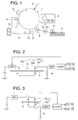
- Fig. 1 is a view showing an outline structure of an example of an image forming apparatus of the present invention.
- Fig. 2 is a circuit diagram for determining charging conditions of a transfer charger according to measured information of the resistance of a transfer sheet.
- Fig. 3 is a circuit diagram for determining charging conditions of the transfer charger according to measured information of the resistance of the transfer sheet.
- Fig. 4 is a timing chart of the control operation according to the present invention by a control apparatus.
- Fig. 5 is a graph showing the relationship between conditions of an electrode roller and an amplifier output.
- Fig. 1 is a view showing an outline structure of an example of an image forming apparatus of the present invention.
- Fig. 2 and Fig. 3 are circuit diagrams for determining charging conditions of a transfer charger according to measured information of the resistance of a transfer sheet.
- Fig. 4 is a timing chart of the control according to the present invention by a control apparatus.
- Fig. 5 is a graph showing the relationship between conditions of an electrode roller and an amplifier output.
- numeral 1 is an image forming body rotating in the arrowed direction.
- Numeral 2 is a cleaning unit for removing residual toners on the surface of the image forming body.
- Numeral 3 is a charger for charging the surface of the cleaned image forming body.
- Numeral 4 is an image exposure light projected onto the uniformly charged surface of the image forming body from a laser beam scanner or a document scanning exposure apparatus.
- Numeral 5 is a developing unit for developing the latent image formed by the image exposure 4 into a toner image.
- Numeral 6 is a sheet feed roller for feeding the uppermost transfer sheet P from a stack of transfer sheets P.
- Numeral 7 are pinch conveyance rollers for sending the transfer sheet P fed by the sheet feed roller 6.
- Numeral 8 is a register roller.
- Pinch conveyance rollers 7 comprise conductive electrode rollers 7a and 7b for feeding a current in the direction of the thickness of the transfer sheet P as shown in Figs. 2 and 3.
- the pinch conveyance rollers 7 temporarily stop when the leading edge of the transfer sheet P comes into contact with the register roller 8, and the transfer sheet P is curved between the pinch conveyance rollers 7 and the register roller 8. After that, the pinch conveyance rollers 7, together with the register roller 8, send the transfer sheet P to a transfer area at which a transfer charger 9 is opposite to the image forming body 1 so that the transfer sheet P is synchronized with the toner image.
- Numeral 10 is a separation charger for separating the transfer sheet P, which has passed through the transfer area and onto which the toner image has been transferred, from the surface of the image forming body 1.
- Numeral 11 is a conveyer for conveying the separated transfer sheet P to a fixing unit 12. The transfer sheet P, onto which the toner image has been fixed by the fixing unit 12, is delivered outside the apparatus.
- One electrode roller 7a of the pinch conveyance rollers 7 shown in Fig. 2 is structured by the first and second electrode rollers 7a1 and 7a2, both having conductive metal surface layers, which are connected with an insulated connecting shaft 7c.
- the other electrode roller 7b has a conductive elastic surface layer made of conductive rubber, etc., wherein the surface layer has enough length to pinch the transfer sheet between the electrode roller 7b and the first and second electrode rollers 7a1 and 7a2, and to convey the transfer sheet.
- One electrode roller 7a of the pinch conveyance rollers 7 shown in Fig. 3 has a metallic surface layer, and the other electrode roller 7b has the conductive elastic surface layer made of conductive rubber, etc. The transfer sheet is pinched between the electrode rollers 7a and 7b, and conveyed.
- a control unit CONT for controlling the overall image forming apparatus turns on a power switch SW of the resistance measuring circuit for a short predetermined period of time.
- the pinch conveyance rollers 7 feed a current in the direction of the thickness of the pinched transfer sheet P.
- This current signal is converted into a voltage signal by the resistance R, and inputted into the control unit CONT through the amplifier AMP.
- the control unit CONT drives the transfer charger 9 and the separation charger 10 through driving circuits D1 and D2 of the transfer charger 9 and the separation charger 10 on the charging conditions in which the maximum transfer efficiency and the separation reliability can be obtained with respect to the resistance of the transfer sheet.
- the control unit CONT may feed a current between electrode rollers 7a and 7b, and may drive the transfer charger 9 and the separation charger 10 according to a signal of the difference between the signal due to the above-described current and the signal obtained when the transfer signal is pinched between the electrode rollers 7a and 7b as shown in Fig.
- the measurement for the resistance is conducted when the conveyance rollers stop.
- the timing chart shown in Fig. 4 shows the above-described control by the control unit CONT and the output from the amplifier AMP to the control unit CONT.
- a period of tl shown in Fig. 5 showing the relationship between conditions of the pinch conveyance roller and the amplifier output while the power switch is on, shows that the transfer sheet P is not pinched between pinch conveyance rollers 7 of the electrode rollers and the rollers 7 stop. Accordingly, the output V1 during the period shows the above-described reference value.
- t1 and t4 respectively show conditions that the pinch conveyance rollers 7 convey the transfer sheet P. Accordingly, outputs V2 and V4 during the periods correspond to the resistance of the transfer sheet obtained by the transfer sheet resistance measuring method disclosed in Japanese Patent Publication Open to Public Inspection JP-A-54 34834.
- Period t3 shows conditions that the pinch conveyance rollers 7 pinch the transfer sheet and stop. Accordingly, output V3 during the period shows the measured value of the resistance of the transfer sheet P. Further,
- the image forming apparatus of the present invention is not limited to the above-described examples, but a light emitting amount of a pre-transfer discharging lamp may also be determined according to the resistance of the transfer sheet P when the pre-transfer discharging lamp is provided between the developing unit 5 and the transfer charger 9. Further, when a transfer sheet guide provided between the sheet feed roller 6 and transfer charger 9 is grounded through a resistor, the resistor may also be switched according to the resistance of the transfer sheet.
- the resistance of the transfer sheet can be stably measured with high accuracy, and charging conditions of the transfer charger and the separation charger are determined according to the measured information. Accordingly, higher transfer efficiency and higher separation reliability can be stably obtained, and only one resistance measuring apparatus for the transfer sheet is enough even when a plurality of sheet feeding means are provided in the apparatus.
Description
Claims (9)
- An image forming apparatus, comprising:a stacking member on which the recording member is stored;processing means for working on a recording member (P) so as to form an image on the recording member;wherein the processing means comprises an image carrying member (1) on which a toner image is formed and transferring means (9) for transferring the toner image onto the recording member,characterized in that,conveying means (7) for conveying the recording member from the stacking member to the processing means along a conveyance passage,registering means (8) for making the recording member temporarily waiting before the recording member is conveyed to the processing means so that the image formation on the recording member is in synchronization with the working of the processing means;measuring means (7, SW, AMP) for measuring a value corresponding to an electric resistance of the recording member,wherein said measuring means has a pair of rollers (7a,7b) in said conveyance passage to convey the recording member in a condition that the recording member is nipped therebetween;said measuring means is adapted to measure a first value corresponding to the resistance in the case that the pair of rollers nip the recording member therebetween and a second value corresponding to the resistance in the case that the pair of rollers do not nip the recording member therebetween, and to obtain the resistance of the recording member on the basis of the first value and the second value;control means (CONT) for determining process conditions to form the image on the recording member on the basis of the resistance of the recording member and for controlling the processing means in accordance with the determined process conditions.
- The apparatus of Claim 1, wherein said measuring means measures the resistance of the recording member on the basis of the difference between the first value and the second value.
- The apparatus of Claim 1, wherein the measuring means measures the value when the conveying means is stopped.
- The apparatus of Claim 1, wherein the measuring means comprises means for applying a current in a direction of the thickness of the recording member.
- The apparatus of Claim 1, wherein the control means determines a transferring condition of the transferring means.
- The apparatus of Claim 5, wherein the transferring condition is a charge condition.
- The apparatus of Claim 1, wherein the processing means further comprises separating means (10) to separate the recording member from the image carrying member.
- The apparatus of Claim 7, wherein the control means determines a separating condition of the separating means.
- The apparatus of Claim 1, wherein the stacking member comprises plural stackers, a common passage is provided for the stackers, and the measuring means is disposed on the common passage.
Applications Claiming Priority (2)
| Application Number | Priority Date | Filing Date | Title |
|---|---|---|---|
| JP320178/93 | 1993-12-20 | ||
| JP5320178A JPH07175350A (en) | 1993-12-20 | 1993-12-20 | Image forming device |
Publications (3)
| Publication Number | Publication Date |
|---|---|
| EP0660197A2 EP0660197A2 (en) | 1995-06-28 |
| EP0660197A3 EP0660197A3 (en) | 1995-08-02 |
| EP0660197B1 true EP0660197B1 (en) | 1998-05-06 |
Family
ID=18118571
Family Applications (1)
| Application Number | Title | Priority Date | Filing Date |
|---|---|---|---|
| EP94309364A Expired - Lifetime EP0660197B1 (en) | 1993-12-20 | 1994-12-14 | Image forming apparatus equipped with a device to measure a resistance of a transfer sheet |
Country Status (3)
| Country | Link |
|---|---|
| US (1) | US5608506A (en) |
| EP (1) | EP0660197B1 (en) |
| JP (1) | JPH07175350A (en) |
Families Citing this family (16)
| Publication number | Priority date | Publication date | Assignee | Title |
|---|---|---|---|---|
| JP3014576B2 (en) * | 1994-02-04 | 2000-02-28 | シャープ株式会社 | Recording medium recognition device |
| EP0775947A1 (en) * | 1995-12-07 | 1997-05-28 | COMPUPRINT S.p.A. | Electrophotographic printing apparatus having a corotron-polarised transfer roller |
| US6058275A (en) * | 1996-11-14 | 2000-05-02 | Minolta Co., Ltd. | Image forming apparatus with controller for controlling image forming conditions according to electrostatic capacitance of standard toner image |
| JP2901560B2 (en) * | 1996-12-24 | 1999-06-07 | 新潟日本電気株式会社 | Color image forming equipment |
| KR100262513B1 (en) * | 1998-05-19 | 2000-08-01 | 윤종용 | Apparatus and method for optimizing transfer environment by detecting the humidity of the printing paper in the electrophotography system |
| KR100317997B1 (en) * | 1999-01-11 | 2001-12-22 | 윤종용 | Method for controlling transfer voltage by paper characteristic resistance in laser beam printer |
| JP2000242089A (en) * | 1999-02-22 | 2000-09-08 | Kyocera Mita Corp | Method for forming image |
| US6243545B1 (en) * | 2000-01-10 | 2001-06-05 | Hewlett-Packard Company | Method and apparatus for controlling a bias of a fixing device |
| US6493523B2 (en) * | 2001-05-11 | 2002-12-10 | Hewlett-Packard Company | Capacitance and resistance monitor for image producing device |
| KR100476971B1 (en) * | 2002-09-12 | 2005-03-16 | 삼성전자주식회사 | Duplex printer and a method of controlling toner image thereby |
| US6804478B2 (en) | 2003-02-18 | 2004-10-12 | Hewlett-Packard Development Company, L.P. | Methods and apparatus for controlling a fuser |
| KR101129003B1 (en) * | 2007-06-21 | 2012-03-23 | 삼성전자주식회사 | Image forming apparatus and method |
| US7957656B2 (en) * | 2008-12-05 | 2011-06-07 | Xerox Corporation | Apparatus, method and system for feedforward of sheet electrostatic tacking parameters to image transfer subsystem in image transfer apparatus |
| US20110311253A1 (en) * | 2010-06-21 | 2011-12-22 | Toshiba Tec Kabushiki Kaisha | Image forming apparatus and image formation processing method |
| JP6840990B2 (en) * | 2016-10-24 | 2021-03-10 | 富士ゼロックス株式会社 | Image forming device |
| JP2022179065A (en) | 2021-05-21 | 2022-12-02 | 富士フイルムビジネスイノベーション株式会社 | Sheet electric resistance measuring unit |
Family Cites Families (11)
| Publication number | Priority date | Publication date | Assignee | Title |
|---|---|---|---|---|
| JPS5357042A (en) * | 1976-11-02 | 1978-05-24 | Fuji Xerox Co Ltd | Trasfer control device |
| JPS5669652A (en) * | 1979-11-13 | 1981-06-11 | Canon Inc | Copying machine provided with copying processing device which is controllable according to environmental change |
| JPS5764270A (en) * | 1980-10-08 | 1982-04-19 | Ricoh Co Ltd | Electrostatic copying method |
| JPS5767969A (en) * | 1980-10-16 | 1982-04-24 | Olympus Optical Co Ltd | Transcription device for electrophotographic copier for copying plural sheets |
| JPS57205761A (en) * | 1981-06-15 | 1982-12-16 | Ricoh Co Ltd | Separation of transfer paper for copying machine |
| JPS57211168A (en) * | 1981-06-22 | 1982-12-24 | Canon Inc | Sheet feeding device |
| JPS5825677A (en) * | 1981-08-07 | 1983-02-15 | Ricoh Co Ltd | Transfer device |
| US5287144A (en) * | 1989-07-05 | 1994-02-15 | Canon Kabushiki Kaisha | Image forming apparatus having transfer charger which is controlled according to ambient conditions |
| JP2964545B2 (en) * | 1990-05-15 | 1999-10-18 | ミノルタ株式会社 | Image forming device |
| JP3264973B2 (en) * | 1991-04-24 | 2002-03-11 | 株式会社リコー | Image forming method |
| JPH04362676A (en) * | 1991-06-10 | 1992-12-15 | Ricoh Co Ltd | Copying machine |
-
1993
- 1993-12-20 JP JP5320178A patent/JPH07175350A/en active Pending
-
1994
- 1994-12-12 US US08/354,507 patent/US5608506A/en not_active Expired - Fee Related
- 1994-12-14 EP EP94309364A patent/EP0660197B1/en not_active Expired - Lifetime
Also Published As
| Publication number | Publication date |
|---|---|
| US5608506A (en) | 1997-03-04 |
| EP0660197A2 (en) | 1995-06-28 |
| JPH07175350A (en) | 1995-07-14 |
| EP0660197A3 (en) | 1995-08-02 |
Similar Documents
| Publication | Publication Date | Title |
|---|---|---|
| EP0660197B1 (en) | Image forming apparatus equipped with a device to measure a resistance of a transfer sheet | |
| US6311039B1 (en) | Sheet conveying apparatus and image forming apparatus provided with the same | |
| US5231452A (en) | Image forming control method using variable state factors and fuzzy computation | |
| US20060056862A1 (en) | Image forming apparatus | |
| US20070041762A1 (en) | Image printing apparatus | |
| US6201937B1 (en) | Image to paper registration utilizing differential transfer | |
| US5455663A (en) | Image forming apparatus including recording material carrying means | |
| US5539508A (en) | Variable length transfer assist apparatus | |
| JP3223004B2 (en) | Image forming device | |
| JP3847875B2 (en) | Image forming apparatus | |
| JP5058649B2 (en) | Fixing device control apparatus and image forming apparatus | |
| JPH05313517A (en) | Image forming device | |
| JPH07187452A (en) | Sheet conveyance device | |
| US5963761A (en) | Area coverage sensor calibration and algorithm for seam detection noise eliminator on a seamed photoreceptor | |
| JP3510008B2 (en) | Printing equipment | |
| KR960038525A (en) | Electrophotographic apparatus and control method thereof | |
| JPH04204149A (en) | Resistance-value measuring device for recording paper in image forming apparatus | |
| JP4225172B2 (en) | Image forming apparatus | |
| JP2825856B2 (en) | Image forming device | |
| JP2019124749A (en) | Controller for power supply for transfer roller, image forming apparatus and multifunction machine, and method for controlling power supply for transfer roller | |
| JP2907960B2 (en) | Transfer device | |
| JPS5860756A (en) | Transfer method | |
| JPS62127770A (en) | Image forming device | |
| JP3264944B2 (en) | Image forming method | |
| CN114355740A (en) | Transfer device and image forming apparatus |
Legal Events
| Date | Code | Title | Description |
|---|---|---|---|
| PUAI | Public reference made under article 153(3) epc to a published international application that has entered the european phase |
Free format text: ORIGINAL CODE: 0009012 |
|
| PUAL | Search report despatched |
Free format text: ORIGINAL CODE: 0009013 |
|
| 17P | Request for examination filed |
Effective date: 19950218 |
|
| AK | Designated contracting states |
Kind code of ref document: A2 Designated state(s): GB |
|
| AK | Designated contracting states |
Kind code of ref document: A3 Designated state(s): DE FR GB IT NL |
|
| 17Q | First examination report despatched |
Effective date: 19950918 |
|
| GRAG | Despatch of communication of intention to grant |
Free format text: ORIGINAL CODE: EPIDOS AGRA |
|
| GRAG | Despatch of communication of intention to grant |
Free format text: ORIGINAL CODE: EPIDOS AGRA |
|
| GRAG | Despatch of communication of intention to grant |
Free format text: ORIGINAL CODE: EPIDOS AGRA |
|
| GRAH | Despatch of communication of intention to grant a patent |
Free format text: ORIGINAL CODE: EPIDOS IGRA |
|
| GRAH | Despatch of communication of intention to grant a patent |
Free format text: ORIGINAL CODE: EPIDOS IGRA |
|
| RBV | Designated contracting states (corrected) |
Designated state(s): GB |
|
| REG | Reference to a national code |
Ref country code: DE Ref legal event code: 8566 |
|
| GRAA | (expected) grant |
Free format text: ORIGINAL CODE: 0009210 |
|
| AK | Designated contracting states |
Kind code of ref document: B1 Designated state(s): GB |
|
| PG25 | Lapsed in a contracting state [announced via postgrant information from national office to epo] |
Ref country code: GB Free format text: LAPSE BECAUSE OF NON-PAYMENT OF DUE FEES Effective date: 19981214 |
|
| PLBE | No opposition filed within time limit |
Free format text: ORIGINAL CODE: 0009261 |
|
| STAA | Information on the status of an ep patent application or granted ep patent |
Free format text: STATUS: NO OPPOSITION FILED WITHIN TIME LIMIT |
|
| 26N | No opposition filed | ||
| GBPC | Gb: european patent ceased through non-payment of renewal fee |
Effective date: 19981214 |