EP0659997A1 - Verbesserungen an Flüssigkeitsfiltergehäusen für Brennkraftmaschinen - Google Patents
Verbesserungen an Flüssigkeitsfiltergehäusen für Brennkraftmaschinen Download PDFInfo
- Publication number
- EP0659997A1 EP0659997A1 EP94402932A EP94402932A EP0659997A1 EP 0659997 A1 EP0659997 A1 EP 0659997A1 EP 94402932 A EP94402932 A EP 94402932A EP 94402932 A EP94402932 A EP 94402932A EP 0659997 A1 EP0659997 A1 EP 0659997A1
- Authority
- EP
- European Patent Office
- Prior art keywords
- tank
- cover
- clamping
- ring
- toothing
- Prior art date
- Legal status (The legal status is an assumption and is not a legal conclusion. Google has not performed a legal analysis and makes no representation as to the accuracy of the status listed.)
- Withdrawn
Links
- 239000007788 liquid Substances 0.000 title claims abstract description 6
- 230000000694 effects Effects 0.000 claims abstract description 7
- 230000014759 maintenance of location Effects 0.000 claims description 11
- 239000004033 plastic Substances 0.000 claims description 6
- 229920003023 plastic Polymers 0.000 claims description 6
- 238000002485 combustion reaction Methods 0.000 claims description 2
- 238000007789 sealing Methods 0.000 description 3
- 230000009975 flexible effect Effects 0.000 description 2
- 238000004519 manufacturing process Methods 0.000 description 2
- 239000000463 material Substances 0.000 description 2
- 239000002184 metal Substances 0.000 description 2
- 229910052751 metal Inorganic materials 0.000 description 2
- 241000731961 Juncaceae Species 0.000 description 1
- 241000735470 Juncus Species 0.000 description 1
- 239000004952 Polyamide Substances 0.000 description 1
- 230000009471 action Effects 0.000 description 1
- 230000000295 complement effect Effects 0.000 description 1
- 230000005489 elastic deformation Effects 0.000 description 1
- 229920001971 elastomer Polymers 0.000 description 1
- 239000000806 elastomer Substances 0.000 description 1
- 238000000034 method Methods 0.000 description 1
- 230000002093 peripheral effect Effects 0.000 description 1
- 229920002647 polyamide Polymers 0.000 description 1
- 230000000717 retained effect Effects 0.000 description 1
Images

Classifications
-
- B—PERFORMING OPERATIONS; TRANSPORTING
- B01—PHYSICAL OR CHEMICAL PROCESSES OR APPARATUS IN GENERAL
- B01D—SEPARATION
- B01D29/00—Filters with filtering elements stationary during filtration, e.g. pressure or suction filters, not covered by groups B01D24/00 - B01D27/00; Filtering elements therefor
- B01D29/11—Filters with filtering elements stationary during filtration, e.g. pressure or suction filters, not covered by groups B01D24/00 - B01D27/00; Filtering elements therefor with bag, cage, hose, tube, sleeve or like filtering elements
- B01D29/114—Filters with filtering elements stationary during filtration, e.g. pressure or suction filters, not covered by groups B01D24/00 - B01D27/00; Filtering elements therefor with bag, cage, hose, tube, sleeve or like filtering elements arranged for inward flow filtration
-
- B—PERFORMING OPERATIONS; TRANSPORTING
- B01—PHYSICAL OR CHEMICAL PROCESSES OR APPARATUS IN GENERAL
- B01D—SEPARATION
- B01D29/00—Filters with filtering elements stationary during filtration, e.g. pressure or suction filters, not covered by groups B01D24/00 - B01D27/00; Filtering elements therefor
- B01D29/88—Filters with filtering elements stationary during filtration, e.g. pressure or suction filters, not covered by groups B01D24/00 - B01D27/00; Filtering elements therefor having feed or discharge devices
- B01D29/90—Filters with filtering elements stationary during filtration, e.g. pressure or suction filters, not covered by groups B01D24/00 - B01D27/00; Filtering elements therefor having feed or discharge devices for feeding
- B01D29/908—Filters with filtering elements stationary during filtration, e.g. pressure or suction filters, not covered by groups B01D24/00 - B01D27/00; Filtering elements therefor having feed or discharge devices for feeding provoking a tangential stream
-
- B—PERFORMING OPERATIONS; TRANSPORTING
- B01—PHYSICAL OR CHEMICAL PROCESSES OR APPARATUS IN GENERAL
- B01D—SEPARATION
- B01D29/00—Filters with filtering elements stationary during filtration, e.g. pressure or suction filters, not covered by groups B01D24/00 - B01D27/00; Filtering elements therefor
- B01D29/88—Filters with filtering elements stationary during filtration, e.g. pressure or suction filters, not covered by groups B01D24/00 - B01D27/00; Filtering elements therefor having feed or discharge devices
- B01D29/92—Filters with filtering elements stationary during filtration, e.g. pressure or suction filters, not covered by groups B01D24/00 - B01D27/00; Filtering elements therefor having feed or discharge devices for discharging filtrate
- B01D29/925—Filters with filtering elements stationary during filtration, e.g. pressure or suction filters, not covered by groups B01D24/00 - B01D27/00; Filtering elements therefor having feed or discharge devices for discharging filtrate containing liquid displacement elements or cores
-
- B—PERFORMING OPERATIONS; TRANSPORTING
- B01—PHYSICAL OR CHEMICAL PROCESSES OR APPARATUS IN GENERAL
- B01D—SEPARATION
- B01D35/00—Filtering devices having features not specifically covered by groups B01D24/00 - B01D33/00, or for applications not specifically covered by groups B01D24/00 - B01D33/00; Auxiliary devices for filtration; Filter housing constructions
- B01D35/14—Safety devices specially adapted for filtration; Devices for indicating clogging
-
- F—MECHANICAL ENGINEERING; LIGHTING; HEATING; WEAPONS; BLASTING
- F02—COMBUSTION ENGINES; HOT-GAS OR COMBUSTION-PRODUCT ENGINE PLANTS
- F02M—SUPPLYING COMBUSTION ENGINES IN GENERAL WITH COMBUSTIBLE MIXTURES OR CONSTITUENTS THEREOF
- F02M37/00—Apparatus or systems for feeding liquid fuel from storage containers to carburettors or fuel-injection apparatus; Arrangements for purifying liquid fuel specially adapted for, or arranged on, internal-combustion engines
- F02M37/22—Arrangements for purifying liquid fuel specially adapted for, or arranged on, internal-combustion engines, e.g. arrangements in the feeding system
- F02M37/32—Arrangements for purifying liquid fuel specially adapted for, or arranged on, internal-combustion engines, e.g. arrangements in the feeding system characterised by filters or filter arrangements
-
- B—PERFORMING OPERATIONS; TRANSPORTING
- B01—PHYSICAL OR CHEMICAL PROCESSES OR APPARATUS IN GENERAL
- B01D—SEPARATION
- B01D2201/00—Details relating to filtering apparatus
- B01D2201/30—Filter housing constructions
- B01D2201/301—Details of removable closures, lids, caps, filter heads
- B01D2201/302—Details of removable closures, lids, caps, filter heads having inlet or outlet ports
-
- B—PERFORMING OPERATIONS; TRANSPORTING
- B01—PHYSICAL OR CHEMICAL PROCESSES OR APPARATUS IN GENERAL
- B01D—SEPARATION
- B01D2201/00—Details relating to filtering apparatus
- B01D2201/30—Filter housing constructions
- B01D2201/301—Details of removable closures, lids, caps, filter heads
- B01D2201/304—Seals or gaskets
-
- B—PERFORMING OPERATIONS; TRANSPORTING
- B01—PHYSICAL OR CHEMICAL PROCESSES OR APPARATUS IN GENERAL
- B01D—SEPARATION
- B01D2201/00—Details relating to filtering apparatus
- B01D2201/40—Special measures for connecting different parts of the filter
-
- B—PERFORMING OPERATIONS; TRANSPORTING
- B01—PHYSICAL OR CHEMICAL PROCESSES OR APPARATUS IN GENERAL
- B01D—SEPARATION
- B01D2201/00—Details relating to filtering apparatus
- B01D2201/40—Special measures for connecting different parts of the filter
- B01D2201/4076—Anti-rotational means
Definitions
- the present invention relates to a liquid filter housing for an internal combustion engine, in particular a diesel filter housing, comprising a tank which is adapted to receive a filter element and which has an opening making it possible to replace said filter element, the housing comprising in addition a removable cover adapted to close said opening, the cover and the tank respectively having two annular bearing surfaces which are arranged opposite one another when the cover closes the opening of the tank and which are adapted to pinch axially between them an annular seal for sealing the opening of the tank, the cover comprising a conduit which passes through it, the tank being intended to be mounted in a fixed position.
- the fixing of the cover to the tank must be done without appreciable rotation of the cover, since the latter comprises a conduit which passes through it, which communicates with the filter element, and which is generally connected to the motor by a flexible hose.
- this fixing of the cover to the tank is done by means of four screws which are distributed around the periphery of the cover, and which pass through an outer rim of the cover and an outer rim of the tank.
- the object of the present invention is in particular to avoid these drawbacks.
- a case of the kind in question is essentially characterized in that it further comprises a rotary clamping ring, which cooperates with the tank and the cover to urge the cover towards the tank by the effect of screwing when the clamping ring is in a so-called angular position of tightening, said ring being able to be placed in a so-called angular position of release, in which the cover can be removed from the opening of the tank, this housing also comprising a retention capable of cooperating with a toothing which extends angularly, this retention member and this toothing being integral one of the ring, the other of the tank or of the cover, the retention member being elastically biased towards the toothing and being adapted to engage in said toothing at least when the tightening ring is in its angular tightening position, to retain said ring as long as it is not subjected to a coupl e exercised it voluntarily.
- clamping ring can act on the cover and the tank in positions radially closer to the annular seal and angularly better distributed than in a screw fixing system, so that a good seal can be obtained by exerting less force on the parts, hence less fatigue of these parts.
- the fact that the clamping ring is retained in its clamping position by the engagement of the retention member in the teeth ensures that the clamping is maintained despite the vibrations of the motor, even if the clamping is not not extremely loud.
- the retention member can engage in said toothing despite the imprecision of its position relative to this toothing at the end of tightening of the ring, since the tightening ring being tightened by means of a predetermined torque, its tightening position may vary slightly from one housing to another, in particular as a function of the differences in friction between the parts and as a function of the differences in wear of the parts.
- diesel filter housing will be described below in the position which is shown in the drawings, that is to say in the vertical position, the cover being directed upwards, but it could possibly be used in another position.
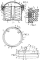
- the liquid filter housing according to the invention which is here a diesel filter housing, comprises a tank 1 adapted to receive a filter element 2, this tank having an opening 3 which allows replacement of the filter element 2, this opening being closed by a cover 4 which is held in place by a clamping ring 9.
- the tank 1, the cover 4 and the ring 9 are made of plastic, for example polyamide 6-6. Other materials could however be envisaged without departing from the scope of the invention.
- the tank 1 has a generally cylindrical shape of revolution about an axis 11, and it is generally intended to be mounted in a fixed position, for example directly on a diesel engine.
- the filter element 2 is simply fitted so removable inside the tank 1.
- This filter element 2 comprises an annular side wall 21 made of a filter material, for example paper, a bottom 22 in the form of a disc which separates the interior of the annular wall 21 with respect to the tank 1, and an upper wall 23 also in the form of a disc which has a central opening 24 and a peripheral rim 25 which is provided with an annular seal 7 made of elastomer.
- a filter material for example paper
- a bottom 22 in the form of a disc which separates the interior of the annular wall 21 with respect to the tank 1
- an upper wall 23 also in the form of a disc which has a central opening 24 and a peripheral rim 25 which is provided with an annular seal 7 made of elastomer.
- the seal 7 is pinched axially between two radial annular surfaces 5 and 6 (FIG. 2) belonging respectively to the tank and to the cover, so as to produce a sealed closure of the opening 3 of the tank by the cover.
- the radial annular surfaces 5 and 6 each comprise an annular ring, respectively 51, 61, the annular seal 7 being clamped axially between the rings 51 and 61. This increases the seal obtained by means of the seal 7, for a given clamping pressure of the cover 4 on the tank 1.
- the liquid to be filtered arrives in the tank 1 through an inlet orifice (not shown), then passes radially through the annular wall 21 of the filter element, and finally flows through the orifice 24 to an outlet duct 8 which is formed in the cover 4, this outlet duct being connected by a flexible pipe (not shown) to the motor supply circuit.
- the seal 7 allows not only a sealed closure of the housing, but also a sealed contact between the tank and the periphery 25 of the upper wall 23 of the filter element, to ensure that all the diesel which passes through the housing passes through the filter wall 21 of the filter element.
- the cover 4 is tightened axially on the seal 7 by means of the clamping ring 9, by a screwing effect.
- the clamping ring 9 has, at its lower axial end, a discontinuous inner flange 15 (Figures 1, 6 and 7) which cooperates with an outer rim 13 also discontinuous of the tank 1 ( Figures 1, 3, 5 and 7), and the clamping ring 9 further comprises, at its upper axial end, ramps clamp 16 ( Figures 1, 6 and 7) which cover complementary clamping ramps 14 ( Figures 1, 4, 5 and 7) disposed at the periphery of the cover 4, cooperating with these clamping ramps to press on the cover 4 .
- the outer rim 13 of the tank has three notches 17 which are angularly distributed regularly at its periphery.
- the outer rim 13 of the tank has at its periphery an elastic tab 10, which extends axially upwards from said rim, and which has at its free end a lug 12 projecting radially outwards, this lug 12 being radially displaceable by elastic deformation of the tab 10.
- the elastic tab 10 is framed by two tabs 19 which extend axially upwards to the same level as the free end of said tab 10.
- the tank 1 comprises, under the external rim 13, a collar 21, which defines with the external rim 13 an annular groove 22.
- the inner flange 15 of the clamping ring 9 has three protruding portions which extend radially inwardly, and which are adapted to each penetrate axially into one of the notches 17 of the outer rim 13 of the tank, to allow mounting of the clamping ring on the tank.
- clamping ramps 16 of the ring 9 are themselves three in number, angularly distributed in a regular manner, but offset from the projecting parts of the inner rim 15.
- clamping ring 9 has internally three toothed zones 11, each formed by a plurality of axial grooves.
- the cover 4 also includes three clamping ramps 14 forming protruding parts radially outwards, thus delimiting three notches 18 between them.
- These indentations 18 are identical to the indentations 17 on the rim of the tank.
- the cover 4 has at its periphery a notch 20 specially shaped to receive the elastic tab 10 and the two tabs 19 which surround it, thereby defining a predetermined angular position of the cover 4 relative to the tank 1.
- the notches 18 of the cover are arranged in correspondence with the notches 17 of the tank, as can be seen in particular in FIG. 5.
- this ring is oriented so that the projecting parts of its inner rim 15 are arranged in correspondence with the notches 17 on the outer rim of the tank, then the clamping ring is axially engaged on the tank by passing the protruding parts of the rim 15 into the notches 17.
- the clamping ring 9 is then rotated (in general by holding the clamping ring in one hand), for example in the direction of screwing, so that the clamping ramps 16 of the ring 9 presses on the clamping ramps 14 of the cover (FIG. 7) at the same time as the discontinuous internal rim 15 of the ring 9 penetrates under the discontinuous external rim 13 of the tank, which allows tightening.
- the elastic tab 10 When the tightening is finished, it is after application of a predetermined tightening torque on the ring 9, the elastic tab 10 is found opposite one of the toothed zones 11, so that the lug 12 engages in one of the grooves in this toothed area, ensuring that the clamping ring 9 remains in its tight position despite the vibrations imparted to the housing by the motor.
- the toothed areas 11 extend angularly enough for the lug 12 to reach one of the toothed areas 11 at the end of tightening, despite the relative imprecision of the final position of the ring after tightening.
Landscapes
- Chemical & Material Sciences (AREA)
- Engineering & Computer Science (AREA)
- Chemical Kinetics & Catalysis (AREA)
- Combustion & Propulsion (AREA)
- Mechanical Engineering (AREA)
- General Engineering & Computer Science (AREA)
- Closures For Containers (AREA)
Applications Claiming Priority (2)
| Application Number | Priority Date | Filing Date | Title |
|---|---|---|---|
| FR9315463 | 1993-12-22 | ||
| FR9315463A FR2714117B1 (fr) | 1993-12-22 | 1993-12-22 | Perfectionnements aux boîtiers de filtres à liquide pour moteur. |
Publications (1)
| Publication Number | Publication Date |
|---|---|
| EP0659997A1 true EP0659997A1 (de) | 1995-06-28 |
Family
ID=9454236
Family Applications (1)
| Application Number | Title | Priority Date | Filing Date |
|---|---|---|---|
| EP94402932A Withdrawn EP0659997A1 (de) | 1993-12-22 | 1994-12-19 | Verbesserungen an Flüssigkeitsfiltergehäusen für Brennkraftmaschinen |
Country Status (2)
| Country | Link |
|---|---|
| EP (1) | EP0659997A1 (de) |
| FR (1) | FR2714117B1 (de) |
Cited By (6)
| Publication number | Priority date | Publication date | Assignee | Title |
|---|---|---|---|---|
| EP0732133A1 (de) * | 1995-03-07 | 1996-09-18 | Lucas Industries Public Limited Company | Fluidbehandlungsapparat |
| DE10118050A1 (de) * | 2001-04-11 | 2002-10-24 | Siemens Ag | Feinfilter für eine Kraftstofffördereinheit |
| WO2010000687A2 (en) * | 2008-07-04 | 2010-01-07 | Ufi Filters S.P.A. | A fuel filter |
| US20120067804A1 (en) * | 2010-09-21 | 2012-03-22 | Zhejiang Qinyuan Water Treatment S. T. Co., Ltd. | Loose-proof structure of a filter cartridge shell |
| WO2018033317A1 (de) * | 2016-08-16 | 2018-02-22 | Mann+Hummel Gmbh | Filterelementanordnung mit dichtelement und filtersystem |
| CN108246024A (zh) * | 2018-03-29 | 2018-07-06 | 四川师范大学 | 一种小型空气过滤器 |
Citations (3)
| Publication number | Priority date | Publication date | Assignee | Title |
|---|---|---|---|---|
| US3322280A (en) * | 1964-06-18 | 1967-05-30 | Fram Corp | Liquid fuel filter and water separator |
| GB2115305A (en) * | 1982-02-24 | 1983-09-07 | Racor Industries Inc | Fuel filter |
| US4857189A (en) * | 1988-10-13 | 1989-08-15 | Everpure, Inc. | Filter cartridge with a lugged concentric closure portion |
-
1993
- 1993-12-22 FR FR9315463A patent/FR2714117B1/fr not_active Expired - Lifetime
-
1994
- 1994-12-19 EP EP94402932A patent/EP0659997A1/de not_active Withdrawn
Patent Citations (3)
| Publication number | Priority date | Publication date | Assignee | Title |
|---|---|---|---|---|
| US3322280A (en) * | 1964-06-18 | 1967-05-30 | Fram Corp | Liquid fuel filter and water separator |
| GB2115305A (en) * | 1982-02-24 | 1983-09-07 | Racor Industries Inc | Fuel filter |
| US4857189A (en) * | 1988-10-13 | 1989-08-15 | Everpure, Inc. | Filter cartridge with a lugged concentric closure portion |
Cited By (11)
| Publication number | Priority date | Publication date | Assignee | Title |
|---|---|---|---|---|
| EP0732133A1 (de) * | 1995-03-07 | 1996-09-18 | Lucas Industries Public Limited Company | Fluidbehandlungsapparat |
| US5914035A (en) * | 1995-03-07 | 1999-06-22 | Lucas Industries Plc | Apparatus for separating water from a fluid |
| DE10118050A1 (de) * | 2001-04-11 | 2002-10-24 | Siemens Ag | Feinfilter für eine Kraftstofffördereinheit |
| DE10118050B4 (de) * | 2001-04-11 | 2004-11-18 | Siemens Ag | Feinfilter für eine Kraftstofffördereinheit |
| WO2010000687A2 (en) * | 2008-07-04 | 2010-01-07 | Ufi Filters S.P.A. | A fuel filter |
| WO2010000687A3 (en) * | 2008-07-04 | 2010-07-15 | Ufi Filters S.P.A. | A fuel filter |
| US20120067804A1 (en) * | 2010-09-21 | 2012-03-22 | Zhejiang Qinyuan Water Treatment S. T. Co., Ltd. | Loose-proof structure of a filter cartridge shell |
| US8623207B2 (en) * | 2010-09-21 | 2014-01-07 | Zhejiang Qinyuan Water Treatment S. T. Co. Ltd. | Loose-proof structure of a filter cartridge shell |
| WO2018033317A1 (de) * | 2016-08-16 | 2018-02-22 | Mann+Hummel Gmbh | Filterelementanordnung mit dichtelement und filtersystem |
| CN108246024A (zh) * | 2018-03-29 | 2018-07-06 | 四川师范大学 | 一种小型空气过滤器 |
| CN108246024B (zh) * | 2018-03-29 | 2020-09-08 | 四川师范大学 | 一种小型空气过滤器 |
Also Published As
| Publication number | Publication date |
|---|---|
| FR2714117B1 (fr) | 1996-03-01 |
| FR2714117A1 (fr) | 1995-06-23 |
Similar Documents
| Publication | Publication Date | Title |
|---|---|---|
| EP1879676B1 (de) | Filterpatrone und montagesystem mit verschlüsselung | |
| CA2503050C (fr) | Dispositif d'assemblage de brides annulaires, en particulier dans une turbomachine | |
| EP0975411B1 (de) | Filter und filterkartusche mit äusserem anschlag für die filtration von flüssigkeiten, die in einem motor oder einer hydraulik zirkulieren | |
| EP3592446B1 (de) | Filter und abnehmbare kartusche mit bypass-ventil | |
| FR2577824A1 (fr) | Cartouche jetable pour separateurs centrifuges | |
| EP2958819A1 (de) | Abgedichtete trommel zum transportieren eines pulverförmigen chemischen produkts | |
| FR2618870A1 (fr) | Collier de serrage pour le raccordement de deux tubes metalliques | |
| FR2860847A1 (fr) | Dispositif de butee de debrayage | |
| FR2488970A1 (fr) | Joint d'etancheite pour paliers de turbochargeur | |
| FR2540955A1 (fr) | Dispositif d'etancheite pour une chambre formee entre des elements interne et externe coaxiaux rotatifs l'un par rapport a l'autre | |
| EP0446538A1 (de) | Vorrichtung und Verfahren zur Befestigung eines Wasserzählers auf einem Sockel | |
| WO2019180353A1 (fr) | Filtre et cartouche amovible, avec deux niveaux d'étanchéité dans un puits de la base du filtre | |
| EP0659997A1 (de) | Verbesserungen an Flüssigkeitsfiltergehäusen für Brennkraftmaschinen | |
| FR2638502A1 (fr) | Vanne a disques pour permettre ou non le passage du fluide | |
| FR2693920A1 (fr) | Perfectionnements aux boîtiers pour filtres à liquide. | |
| FR2716519A1 (fr) | Perfectionnement aux thermostats à boîtier intégré. | |
| EP0663226A1 (de) | Filter und Filterkartusche mit freiem Zentralkern für die Filtration von Motorflüssigkeiten | |
| WO2002028248A1 (fr) | Recipient de travail pour robot menager, comportant un axe d'entrainement rotatif etanche | |
| FR2954712A1 (fr) | Element filtrant a levre d'etancheite destine a un filtre a liquides | |
| FR2549915A1 (fr) | Perfectionnements aux systemes de vissage comprenant un ecrou a embase et aux composants de ces systemes | |
| FR2864910A1 (fr) | Filtre a liquide pour moteur a combustion interne et cartouche filtrante interchangeable pour un tel filtre. | |
| EP1649472B1 (de) | Elektromagnetisches ventil, verfahren zum anbringen einer solenoidspule an dem elektromagnetischen ventil und verfahren zum ablösen der solenoidspule von diesem elektromagnetischen ventil | |
| FR2691505A1 (fr) | Dispositif d'étanchéité d'arbre de moteur à combustion interne, en particulier de véhicule automobile. | |
| FR2480896A1 (fr) | Soupape a siege conique | |
| EP0328433B1 (de) | Gleitringdichtung |
Legal Events
| Date | Code | Title | Description |
|---|---|---|---|
| PUAI | Public reference made under article 153(3) epc to a published international application that has entered the european phase |
Free format text: ORIGINAL CODE: 0009012 |
|
| AK | Designated contracting states |
Kind code of ref document: A1 Designated state(s): DE ES GB IT NL SE |
|
| RAP1 | Party data changed (applicant data changed or rights of an application transferred) |
Owner name: FILTRAUTO |
|
| 17P | Request for examination filed |
Effective date: 19950619 |
|
| 17Q | First examination report despatched |
Effective date: 19960902 |
|
| GRAG | Despatch of communication of intention to grant |
Free format text: ORIGINAL CODE: EPIDOS AGRA |
|
| GRAH | Despatch of communication of intention to grant a patent |
Free format text: ORIGINAL CODE: EPIDOS IGRA |
|
| STAA | Information on the status of an ep patent application or granted ep patent |
Free format text: STATUS: THE APPLICATION IS DEEMED TO BE WITHDRAWN |
|
| 18D | Application deemed to be withdrawn |
Effective date: 19970718 |