EP0659975B1 - Filtre de puits avec diamètre extérieur uniforme - Google Patents
Filtre de puits avec diamètre extérieur uniforme Download PDFInfo
- Publication number
- EP0659975B1 EP0659975B1 EP94118818A EP94118818A EP0659975B1 EP 0659975 B1 EP0659975 B1 EP 0659975B1 EP 94118818 A EP94118818 A EP 94118818A EP 94118818 A EP94118818 A EP 94118818A EP 0659975 B1 EP0659975 B1 EP 0659975B1
- Authority
- EP
- European Patent Office
- Prior art keywords
- screen
- support members
- well
- connecting section
- portions
- Prior art date
- Legal status (The legal status is an assumption and is not a legal conclusion. Google has not performed a legal analysis and makes no representation as to the accuracy of the status listed.)
- Expired - Lifetime
Links
- 239000012530 fluid Substances 0.000 claims description 22
- 230000002093 peripheral effect Effects 0.000 claims description 8
- 239000007789 gas Substances 0.000 description 9
- 239000007787 solid Substances 0.000 description 7
- 238000004519 manufacturing process Methods 0.000 description 6
- 239000002002 slurry Substances 0.000 description 5
- 230000008878 coupling Effects 0.000 description 4
- 238000010168 coupling process Methods 0.000 description 4
- 238000005859 coupling reaction Methods 0.000 description 4
- 238000012856 packing Methods 0.000 description 4
- 239000004576 sand Substances 0.000 description 4
- 238000007789 sealing Methods 0.000 description 3
- 230000015572 biosynthetic process Effects 0.000 description 2
- 230000005484 gravity Effects 0.000 description 2
- 238000003780 insertion Methods 0.000 description 2
- 230000037431 insertion Effects 0.000 description 2
- 239000000463 material Substances 0.000 description 2
- 239000003129 oil well Substances 0.000 description 2
- 238000005067 remediation Methods 0.000 description 2
- 239000000565 sealant Substances 0.000 description 2
- XLYOFNOQVPJJNP-UHFFFAOYSA-N water Substances O XLYOFNOQVPJJNP-UHFFFAOYSA-N 0.000 description 2
- 229910000831 Steel Inorganic materials 0.000 description 1
- 230000018044 dehydration Effects 0.000 description 1
- 238000006297 dehydration reaction Methods 0.000 description 1
- 230000009977 dual effect Effects 0.000 description 1
- 238000001914 filtration Methods 0.000 description 1
- 230000009545 invasion Effects 0.000 description 1
- 238000002955 isolation Methods 0.000 description 1
- 238000000034 method Methods 0.000 description 1
- 239000002245 particle Substances 0.000 description 1
- 239000011148 porous material Substances 0.000 description 1
- 238000007790 scraping Methods 0.000 description 1
- 239000010959 steel Substances 0.000 description 1
- 239000011800 void material Substances 0.000 description 1
- 238000010618 wire wrap Methods 0.000 description 1
Images


Classifications
-
- E—FIXED CONSTRUCTIONS
- E21—EARTH OR ROCK DRILLING; MINING
- E21B—EARTH OR ROCK DRILLING; OBTAINING OIL, GAS, WATER, SOLUBLE OR MELTABLE MATERIALS OR A SLURRY OF MINERALS FROM WELLS
- E21B43/00—Methods or apparatus for obtaining oil, gas, water, soluble or meltable materials or a slurry of minerals from wells
- E21B43/02—Subsoil filtering
- E21B43/08—Screens or liners
- E21B43/088—Wire screens
Definitions
- This invention relates generally to the field of oil well, gas well, water well and subterranean pollution remediation well equipment.
- Wire wrapped screens and prepacked screens are examples of devices used inside a drilled hole.
- the drilled hole may be left open or may have a casing or liner cemented and perforated prior to positioning such a device. Openings in such screens may be designed to stop, or bridge undesirable solids contained in fluids or gases.
- Screens and well liners are often surrounded by filter aids.
- the filter aids consist commonly of gravel.
- the openings in the screens and liners are designed to stop, or bridge the undesirable solids contained in the produced fluids or gases.
- Prepacked screens, porous material filter devices and such are examples of devices that incorporate a filter medial in the screen body. These devices are used for the same purpose and these filter aids commonly consist of gravel.
- Multiple wrapped screens provide two or more concentric wire wrappings which act as multiple filters in one device to prevent intervention of undesirable solids and are often used with filter aids, such as gravel, in the well bore.
- screen units of conventional well screens usually consist of lengths (joints) of from 5 to 10 meters with short lengths of blank (non-screen) pipe at each end.
- the purposes of the short length of blank pipe at each end are (1) to provide a means of connecting the joints together at a well site and (2) to facilitate holding each screen joint in a well-head as the joints are assembled for lowering into the well.
- the length of blank sections at the ends of each joint of screen must be long enough to allow for threads required for connecting the joints, and must be long enough to allow room to hang each joint in the well-head while joints are connected together.
- the total blank length is commonly 0.5 to 1 meter, after two joints have been connected together.
- a screen consisting of screen units which are connected together is commonly lowered, and centrallized, in a well bore to a position adjacent to a fluid or gas productive subterranian formation, wherefrom the fluid or gas can flow radially through the screen.
- the screen prevents entrance of undesirable solid particles and allows flow of fluid or gas inside the screen to be produced to the surface.
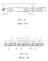
- a problem which arises from the conventional type of well screen installed in-such a high angle well is that, in inserting a screen in a wellbore, the screen is not centrallized as in the case of a screen in a vertical wellbore but the screen is inserted with a side thereof coming into contact with the bottom surface of the wellbore. Therefore, as shown in Fig.
- Another problem arising from a high angle wellbore is that gravel is not packed uniformly due to existence of the blank portion in the screen.
- Gravel is normally packed most tightly in a location in an annulus between the screen and the wellbore where fluid carrying the gravel circulates through the screen. Therefore, gravel cannot be packed so tightly in an annulus about the blank portion as in an annulus about the screen portion.
- gravel can be packed to some degree about the blank portion due to gravity but, in a high angle wellbore, as shown in Fig. 15, gravel h moves toward the bottom side of a wellbore w due to gravity and cannot be packed in a space about a blank portion b, so that a space i which is not packed with gravel is generated in the vicinity of the blank portion b.
- U.S. Patent No. 4,945,991, Jones, L.G., "Methods for Gravel Packing Wells” discloses a screen with substantially rectangular perforated shunt tubes attached to the outside of a screen longitudinally over the entire length of the screen, and connected between all sectional lengths of screens attached together to provide flow paths for the gravel laden fluid to flow into and pack voids or unpacked areas of the screen/wellbore annulus. This device allows the gravel/fluid slurry to enter and flow through multiple flow paths near or above the screen and to thereafter flow both down the screen/wellbore annulus or down one or more of the appendaged perforated shunt tubes.
- connecting section means a threaded tube section provided at an end of each screen unit for connection with an adjacent screen unit and a blank section adjacent to this threaded tube section which has been provided in the screen unit of the conventional Well screen for hanging the screen unit at the well head.
- the outer diameter equalizing means comprises a plurality of support members extending in the axial direction of screen disposed cylindrically at a predetermined interval in the circumferential direction of the screen about at least said one conecting section of at least one of the screen units, and wire means wound on the outer periphery of said support members so as to form slits of a predetermined width, said connecting section being formed with openings which allow flow of fluid between the inside and the outside of said screen unit through the slits of said wire means.
- the surfaces of the adjacent screen units become continuously flush with each other without producing any step in the connecting sections. Accordingly, in inserting the screen into a high angle wellbore, the foremost lower edge portion of each screen unit of the advancing screen does not scrape up the earth of the bottom surface of the wellbore and, therefore, heaping of earth in front of the connecting section of the screen unit can be effectively prevented.
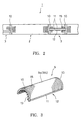
- Figs. 1 to 7 show an embodiment of the well screen according to the invention.
- the outer diameter equalizing means is constructed as a screen jacket which is made of two screen portions each of which includes a plurality of support rods and a wire wound on the outer periphery of the support rods.
- a well screen 1 is made of a plurality of screen units 2 connected in series.
- Each of the screen units 2 has connecting sections 3 provided at both ends and a screen section 4 between the connecting sections 3.
- the screen section 4 of each screen unit 2 includes a pipe 5 formed with fluid intake perforations 5a at a predetermined interval, support rods 6 extending in the axial direction of the screen 1 disposed cylindrically at a predetermined interval in the circumferential direction of the screen 1 and a wire 8 such as a wedge wire wound on the outer periphery of the support rods 6 so as to form slits 7 of a predetermined width.
- the support rods 6 are made of plate-like members which have a predetermined height in the radial direction of the screen 1 and have a substantially triangular cross section at one end.
- the wire 8 is welded to the support rods 6 at respective crossing points between the wire 8 and the support rods 6.
- the connecting section 4 is formed by extending the pipe 5 of the screen section 4 with its diameter being maintained unchanged.
- a male screw 3a is formed on one connecting section 3 of one of the screen units 2 and a female screw 3b is formed on the other connecting section 3 of the screen unit 2.
- the male screw 3a and the female screw 3b of opposite connecting sections of two adjacent screen units 2 are threaded together to connect the screen units 2.
- a screen jacket 9 consisting of two screen portions 9a, 9b each having a semi-circular cross section as shown in Fig. 3 is disposed in such a manner that it will embrace the mutually connected connecting sections 3.
- Each of these screen portions 9a, 9b includes a frame 12 consisting of semi-circular flanges 10, 10 provided at both ends of the screen portion 9a (9b) in the axial direction and straight frame bars 11, 11 provided at both ends of the screen portion 9a (9b) in the circumferential direction, support rods 13 welded to this frame 12, extending in the axial direction and disposed at predetermined interval in the circumferential direction, and a wire 15 wound on the outer periphery of the support rods 13 to form slits 14 of a predetermined width.
- the connecting section 3 is formed with perforations 3c to allow flow of fluid between the outside and the inside of the screen unit 2 through the slits 14 of the wire 15 in the connecting section 3.
- the upper connecting section 3 of a preceding screen unit 2 which is suspended in the wellbore is threaded with the lower connecting section of a following screen unit 2.
- the screen portions 9a, 9b of the screen jacket 9 are mounted on the connecting sections 3 and the screen portions 9a and 9b are welded together at the straight frames 11.
- the screen portions 9a, 9b are also welded at the semi-circular flanges 10 to flanges 16 of adjacent screen sections 4 to seal the screen jacket 9 against invasion of sands from outside.
- Fig. 4 shows another example of connecting two screen portions of the screen jacket 9.
- two screen portions 9a, 9b are connected to each other by means of a hinge 17 at one end in the circumferential direction so that the two screen portions 9a, 9b are openable from a closed state.
- the same components as those in Fig. 1 are designated by the same reference characters and description thereof will be omitted.
- the two screen portions 9a, 9b may be connected to each other by means of bolts and nuts at the straight frame bars 11.
- Fig. 5 shows another example of sealing of the screen jacket 9 mounted on the connecting section 3.
- a small gap is provided between the flanges 10 of the screen portions 9a, 9b of the screen jacket 9 and the flanges 16 of the screen sections 4 and a seal member 18 made of rubber, sealant or the like material is filled in this gap to seal the screen jacket 9 from the outside.
- Fig. 6 shows another example of sealing of the screen jacket 9 mounted on the connecting section 3.
- the flanges 10 of the screen portions 9a, 9b are in abutting engagement with the flanges 16 of the screen sections 4 and the flanges 10 and 16 which are thus in abutting engagement with each other are bound by annular steel bands 19 which is fastened tightly about the flanges 10 and 16 by means of an unillustrated fastening means to provide a seal of the screen jacket 4 from the outside.
- the support rods and the wire wound about these support rods in the connecting section of the screen unit are constructed in the form of the screen jacket consisting of plural screen portions divided circumferentially.
- these support rods and the wire in the connecting section may be constructed as a single cylindrical screen jacket which is not divided circumferentially in plural portions and this screen jacket may be slipped on the connecting sections of two adjacent screen units.
- a gap produced between the screen jacket and the adjacent screen units should desirably be sealed by means of O-rings or other sealing means.
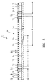
- Fig. 8 shows another embodiment of the well screen made according to the invention.
- support rods 36 and a wire 38 provided in a connecting section 33 of an upper screen unit 30 are formed by extending support rods 36 and a wire 38 wound thereon in a portion other than the connecting section 33, that is, a screen section 34 integrally and continuously over the outer periphery of the connecting section 33 to the end of the connecting section 33.
- a pipe 5 in the connecting section 33 is formed with fluid intake perforations 33c.
- the screen unit 30 of which one end has the above described structure has, at the other end, no support rods or screen wire in a connecting section 31 adjacent to the screen section 34 and has no fluid intake perforations as shown in a lower screen unit 30 of Fig. 8.
- This connecting section 31 is formed with a diametrically opposed pair of perforations 31b for inserting a support member 40 therethrough for suspending the screen unit 30 from the peripheral edge portion of the wellhead.
- the support member 40 is previously inserted through the perforations 31b of the connecting section 31 of the lower screen unit 30 and this screen unit 30 is suspended in the wellbore with the support member 40 crossing the wellbore and supported at the peripheral edge of the wellhead.
- a male screw 33a of the upper screen unit 30 is threaded with a female screw 31a of the lower screen unit 30 until a flange 37 of the upper screen unit 30 is lowered to a position shown by a dotted line in the figure.
- the support member 40 is pulled off the perforations 31b and a gap between flanges 37 and 38 including the perforations 31b is sealed by means of a sealant or the like material.
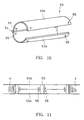
- Figs. 9 to 12 show another embodiment of the invention.
- the outer diameter equalizing means consists of a cylindrical cover plate which is composed of portions having a form obtained by dividing a cylinder in the circumferential direction.
- the cover plate has an outer diameter which is substantially equal to the outer diameter of a screen portion other than the connecting section.
- the same components as those in the embodiment of Figs. 1 to 8 are designated by the same reference characters and description thereof is omitted.
- annular coupling 50 for enlarging the diameter is mounted on one end of a connecting section of a lower screen unit 2.
- the coupling 50 is formed with a female screw 50a on the inner peripheral surface thereof.
- a connecting portion 3 of an upper screen unit 2 is formed with a male screw 51 which can be threaded with the female screw 50a.
- Cylindrical cover plates 53, 53 each of which is made of two plate portions 53a, 53a of a semi-circular cross section which are hingedly connected to each other by means of a hinge 54 are disposed about the mutually connected connecting sections 3, 3 of the upper and lower screen units 2, 2 so as to embrace the connecting sections 3, 3.
- Each of the cover plates 53, 53 is formed at end portions thereof with screw insertion holes 55 and a pipe 5 in the connecting sections 3, 3 is formed at corresponding positions with screw holes 56 (Fig. 12).
- the manner of fixing the cylindrical cover plates 53 is not limited to the above described manner but various other means including those used for fixing the screen jacket in the embodiment of Figs. 1 to 7 may be employed.
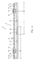
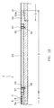
- Fig. 16 shows a still another embodiment of the invention.
- the same components as those in the embodiment of Figs. 1 to 7 are designated by the same reference characters and description thereof is omitted.
- cylindrical cover plates 60, 61 which constitute the outer diameter equalizing means are welded to end portions of support rods 6 to embrace connecting sections 3, 3 of adjacent screen units 2, 2.
- the cover plates 60, 61 are disposed at such location that, when the connecting sections 3, 3 are connected to each other, a part of the outer peripheral surface of the cover plate 60 is in contact with a part of the inner peripheral surface of the cover plate 61.
- one connecting section 3 is rotated for threaded engagement with the other connecting section 3
- one of the cover plates 60, 61 of the rotating connecting section 3 comes into engagement with the other to achieve the structure in which the outer surfaces of the adjacent screen units 2, 2 become flush with respect to each other as shown in Fig. 16.
- cover plates 60, 61 may be replaced by cylindrical screens and the connecting sections 3, 3 may be formed with fluid intake perforations.
- the inner peripheral surface of the cover plate 61 and the outer peripheral surface of the cover plate 60 need not necessarily be in contact with each other but there may be formed a gap between these surfaces.
- This invention is applicable to the well screens having a perforated pipe base as described above and also to a selective isolation type screen disclosed in U.S. Patent No. 4,771,829.
- a spiral wire or a plurality of rings arranged with a predetermined interval in the axial direction of the screen as disclosed in U.S. Patent No. 4,657,079 may be used.
- This invention is also applicable to all types of well screens including a well screen having shunt tubes as disclosed in U.S. Patent No. 4,945,991 and a dual cylinder screen as disclosed in Japanese Patent Application Laid-open No. Hei-5-44386.
Landscapes
- Life Sciences & Earth Sciences (AREA)
- Engineering & Computer Science (AREA)
- Geology (AREA)
- Mining & Mineral Resources (AREA)
- Chemical & Material Sciences (AREA)
- Dispersion Chemistry (AREA)
- Physics & Mathematics (AREA)
- Environmental & Geological Engineering (AREA)
- Fluid Mechanics (AREA)
- General Life Sciences & Earth Sciences (AREA)
- Geochemistry & Mineralogy (AREA)
- Filtration Of Liquid (AREA)
Claims (14)
- Filtre de puits (1) constitué d'une pluralité d'unités de filtrage (2) raccordées en série, chacune desdites unités de filtrage (2) comportant une section de raccordement cylindrique (3a, 3b) au moins à une de ses extrémités et incluant une pluralité d'éléments de support (6) s'étendant dans la direction axiale du filtre (1), disposés selon un cylindre autour d'une section du filtre (1) autre que la section de raccordement (3a, 3b) et espacés d'une distance prédéterminée dans la direction circonférentielle du filtre (1), et également des moyens filaires (8) enroulés sur la périphérie extérieure desdits éléments de support (6) de façon à former des fentes (7) de largeur prédéterminée, celles des sections de raccordement (3a, 3b) qui sont adjacentes auxdites unités de filtrage (2) ayant un diamètre extérieur qui est sensiblement égal au diamètre extérieur des sections de filtre adjacentes (4), caractérisé en ce qu'au moins une section de raccordement (3a, 3b) d'au moins une des unités de filtrage (2, 30) comprend également une pluralité d'éléments de support (13, 36) s'étendant dans la direction axiale du filtre (1), disposés selon un cylindre à une distance prédéterminée dans la direction circonférentielle du filtre (1) autour desdites sections de raccordement (3a, 3b, 33) et des moyens filaires (15, 38) enroulés sur la périphérie extérieure desdits éléments de support (13, 36) de façon à former des fentes (14) de largeur prédéterminée, ladite section de raccordement (3a, 3b, 33) étant formée avec des ouvertures (3c, 33c) qui permettent l'écoulement de fluide entre l'intérieur et l'extérieur de ladite unité de filtrage (2, 30) par les fentes (14) desdits moyens filaires (15, 38).
- Filtre de puits selon la revendication 1 dans lequel lesdits éléments de support (13) disposés dans les sections de raccordement (3) et lesdits moyens filaires (14) enroulés sur la périphérie extérieure desdits éléments de support (13) sont réalisés sous forme d'une chemise de filtre (9) consistant en des portions de filtre (9a, 9b) obtenues en fractionnant un filtre cylindrique dans la direction circonférentielle, lesdites portions de filtre (9a, 9b) étant raccordées entre elles.
- Filtre de puits selon la revendication 2 dans lequel les portions de filtre (9a, 9b) de la chemise de filtre (9) sont soudées entre elles.
- Filtre de puits selon la revendication 2 dans lequel les portions de filtre (9a, 9b) de la chemise de filtre (9) sont raccordées entre elles de façon articulée.
- Filtre de puits selon la revendication 2 dans lequel les portions de filtre (9a, 9b) des chemises de filtre (9) sont raccordées entre elles au moyen de boulons.
- Filtre de puits selon la revendication 2 dans lequel les portions de filtre (9a, 9b) de la chemise de filtre (9) sont raccordées entre elles par liaison par une ceinture.
- Filtre de puits selon la revendication 1 dans lequel lesdits éléments de support (36) disposés dans la section de raccordement (33) et lesdits moyens filaires (38) enroulés sur la périphérie extérieure desdits éléments de support (36) sont formés par prolongement intégral et continu des éléments de support disposés dans la section (34) du filtre (1) autre que la section de raccordement (33), et des moyens filaires enroulés sur la périphérie de celle-ci en direction de la périphérie extérieure de ladite section de raccordement (33).
- Filtre de puits selon la revendication 7 dans lequel une section de raccordement (31) d'une unité de filtrage adjacente (30), se raccordant à ladite section de raccordement (33) dans laquelle lesdits éléments de support (36) et lesdits moyens filaires (38) sont formés par prolongement des éléments de support et des moyens filaires de la section (34) du filtre (1) autre que la section de raccordement (33), comporte une portion dans laquelle il n'y a pas d'éléments de support ni de moyens filaires et qui est formée avec une paire de perforations diamétralement opposées (31b) pour insertion d'un élément de support (40) utilisé pour suspendre l'unité de filtrage adjacente (30) à une portion de bord périphérique d'une tête de puits.
- Filtre de puits (1) composé d'une pluralité d'unités de filtrage (2) raccordées en série, chacune desdites unités de filtrage (2) comportant une section de raccordement cylindrique (3a, 3b) au moins à une de ses extrémités et incluant une pluralité d'éléments de support (6) s'étendant dans la direction axiale du filtre (1) disposés selon un cylindre autour d'une section du filtre (1) autre que la section de raccordement (3a, 3b) et espacés d'une distance prédéterminée dans la direction circonférentielle du filtre (1), et également des moyens filaires (8) enroulés sur la périphérie extérieure desdits éléments de support (6) de façon à former des fentes (7) de largeur prédéterminée, celles des sections de raccordement (3a, 3b) qui sont adjacentes auxdites unités de filtrage (2) ayant un diamètre extérieur qui est sensiblement égal au diamètre extérieur des sections de filtre adjacentes (4), caractérisé en ce que lesdites sections de raccordement (3a, 3b) comprennent une plaque de recouvrement cylindrique (53) qui est constituée de portions (53a, 53b) obtenues en fractionnant un cylindre dans la direction circonférentielle, le diamètre extérieur de ladite plaque de recouvrement (53) étant sensiblement égal au diamètre extérieur de la section (4) de l'unité de filtrage (2) autre que la section de raccordement (3a, 3b).
- Filtre de puits selon la revendication 9 dans lequel les portions (53a, 53b) de la plaque de recouvrement (53) sont raccordées entre elles de façon articulée.
- Filtre de puits selon la revendication 9 dans lequel les portions (53a, 53b) de la plaque de recouvrement (53) sont soudées entre elles.
- Filtre de puits selon la revendication 9 dans lequel les portions (53a, 53b) de la plaque de recouvrement (53) sont raccordées entre elles au moyen de boulons.
- Filtre de puits selon la revendication 9 dans lequel les portions (53a, 53b) de la plaque de recouvrement (53) sont raccordées entre elles au moyen d'une ceinture.
- Filtre de puits (1) composé d'une pluralité d'unités de filtrage (2) raccordées en série, chacune desdites unités de filtrage (2) comportant une section de raccordement cylindrique (3a, 3b) au moins à une de ses extrémités et incluant une pluralité d'éléments de support (6) s'étendant dans la direction axiale du filtre (1), disposés selon un cylindre autour d'une section du filtre (1) autre que la section de raccordement (3a, 3b), et espacés d'une distance prédéterminée dans la direction circonférentielle du filtre (1), et également des moyens filaires (8) enroulés sur la périphérie extérieure desdits éléments de support (6) de façon à former des fentes (7) de largeur prédéterminée, celles des sections de raccordement (3a, 3b) qui sont adjacentes auxdites unités de filtrage (2) ayant un diamètre extérieur qui est sensiblement égal au diamètre extérieur de sections de filtre adjacentes (4) caractérisé en ce que lesdites sections de raccordement adjacentes (3a, 3b) comprennent une paire de plaques de recouvrement cylindriques (60, 61), ou filtres cylindriques, fixées à des portions d'extrémité de deux unités de filtrage adjacentes (2, 2), lesdites plaques de recouvrement (60, 61), ou filtres, étant disposées en un emplacement tel que, lorsque lesdites sections de raccordement (3a, 3b) sont raccordées entre elles, l'une (60) desdites plaques de recouvrement, ou filtres, est située partiellement à l'intérieur de l'autre plaque de recouvrement (61), ou filtre.
Applications Claiming Priority (3)
| Application Number | Priority Date | Filing Date | Title |
|---|---|---|---|
| JP338870/93 | 1993-12-02 | ||
| JP5338870A JPH07158124A (ja) | 1993-12-02 | 1993-12-02 | 均一外径を有する井戸用スクリーン |
| JP33887093 | 1993-12-02 |
Publications (3)
| Publication Number | Publication Date |
|---|---|
| EP0659975A2 EP0659975A2 (fr) | 1995-06-28 |
| EP0659975A3 EP0659975A3 (fr) | 1997-03-12 |
| EP0659975B1 true EP0659975B1 (fr) | 2001-05-30 |
Family
ID=18322172
Family Applications (1)
| Application Number | Title | Priority Date | Filing Date |
|---|---|---|---|
| EP94118818A Expired - Lifetime EP0659975B1 (fr) | 1993-12-02 | 1994-11-30 | Filtre de puits avec diamètre extérieur uniforme |
Country Status (9)
| Country | Link |
|---|---|
| US (1) | US5787980A (fr) |
| EP (1) | EP0659975B1 (fr) |
| JP (1) | JPH07158124A (fr) |
| CN (1) | CN1109548A (fr) |
| AU (1) | AU7906994A (fr) |
| BR (1) | BR9404805A (fr) |
| CA (1) | CA2136694A1 (fr) |
| DE (1) | DE69427338T2 (fr) |
| RU (1) | RU94042229A (fr) |
Cited By (7)
| Publication number | Priority date | Publication date | Assignee | Title |
|---|---|---|---|---|
| US7650944B1 (en) | 2003-07-11 | 2010-01-26 | Weatherford/Lamb, Inc. | Vessel for well intervention |
| US7712523B2 (en) | 2000-04-17 | 2010-05-11 | Weatherford/Lamb, Inc. | Top drive casing system |
| US7730965B2 (en) | 2002-12-13 | 2010-06-08 | Weatherford/Lamb, Inc. | Retractable joint and cementing shoe for use in completing a wellbore |
| US7887103B2 (en) | 2003-05-22 | 2011-02-15 | Watherford/Lamb, Inc. | Energizing seal for expandable connections |
| US7895726B2 (en) | 2003-05-22 | 2011-03-01 | Weatherford/Lamb, Inc. | Tubing connector and method of sealing tubing sections |
| US7938201B2 (en) | 2002-12-13 | 2011-05-10 | Weatherford/Lamb, Inc. | Deep water drilling with casing |
| USRE42877E1 (en) | 2003-02-07 | 2011-11-01 | Weatherford/Lamb, Inc. | Methods and apparatus for wellbore construction and completion |
Families Citing this family (49)
| Publication number | Priority date | Publication date | Assignee | Title |
|---|---|---|---|---|
| US6789822B1 (en) * | 1997-03-21 | 2004-09-14 | Weatherford/Lamb, Inc. | Expandable slotted tubing string and method for connecting such a tubing string |
| US6742596B2 (en) | 2001-05-17 | 2004-06-01 | Weatherford/Lamb, Inc. | Apparatus and methods for tubular makeup interlock |
| GB9817246D0 (en) * | 1998-08-08 | 1998-10-07 | Petroline Wellsystems Ltd | Connector |
| GB2340858A (en) | 1998-08-24 | 2000-03-01 | Weatherford Lamb | Methods and apparatus for facilitating the connection of tubulars using a top drive |
| GB2340859A (en) | 1998-08-24 | 2000-03-01 | Weatherford Lamb | Method and apparatus for facilitating the connection of tubulars using a top drive |
| GB2340857A (en) | 1998-08-24 | 2000-03-01 | Weatherford Lamb | An apparatus for facilitating the connection of tubulars and alignment with a top drive |
| GB2347441B (en) | 1998-12-24 | 2003-03-05 | Weatherford Lamb | Apparatus and method for facilitating the connection of tubulars using a top drive |
| GB2345074A (en) | 1998-12-24 | 2000-06-28 | Weatherford Lamb | Floating joint to facilitate the connection of tubulars using a top drive |
| US6644406B1 (en) | 2000-07-31 | 2003-11-11 | Mobil Oil Corporation | Fracturing different levels within a completion interval of a well |
| US6464007B1 (en) | 2000-08-22 | 2002-10-15 | Exxonmobil Oil Corporation | Method and well tool for gravel packing a long well interval using low viscosity fluids |
| GB0021212D0 (en) | 2000-08-29 | 2000-10-18 | Kier Construction Ltd | Screen assembly for combined sewer overflow weir |
| GB2371319B (en) | 2001-01-23 | 2003-08-13 | Schlumberger Holdings | Completion Assemblies |
| US6644412B2 (en) * | 2001-04-25 | 2003-11-11 | Weatherford/Lamb, Inc. | Flow control apparatus for use in a wellbore |
| US6588506B2 (en) | 2001-05-25 | 2003-07-08 | Exxonmobil Corporation | Method and apparatus for gravel packing a well |
| JP2003314184A (ja) * | 2002-04-26 | 2003-11-06 | Tadayoshi Nagaoka | 長手方向スキッドロッド付円筒状井戸用スクリーン |
| GB0215668D0 (en) * | 2002-07-06 | 2002-08-14 | Weatherford Lamb | Coupling tubulars |
| GB0221220D0 (en) * | 2002-09-13 | 2002-10-23 | Weatherford Lamb | Expanding coupling |
| GB0221585D0 (en) * | 2002-09-17 | 2002-10-23 | Weatherford Lamb | Tubing connection arrangement |
| GB0222321D0 (en) * | 2002-09-25 | 2002-10-30 | Weatherford Lamb | Expandable connection |
| US6981547B2 (en) * | 2002-12-06 | 2006-01-03 | Weatherford/Lamb, Inc. | Wire lock expandable connection |
| US7870898B2 (en) * | 2003-03-31 | 2011-01-18 | Exxonmobil Upstream Research Company | Well flow control systems and methods |
| MXPA05010320A (es) * | 2003-03-31 | 2005-11-17 | Exxonmobil Upstream Res Co | Aparato y metodo para completacion, produccion e inyeccion de sondeo. |
| US7025135B2 (en) * | 2003-05-22 | 2006-04-11 | Weatherford/Lamb, Inc. | Thread integrity feature for expandable connections |
| US7281319B1 (en) | 2004-04-30 | 2007-10-16 | Daniel Allford | Apparatus for manufacturing wire wound filter screens |
| WO2006063207A2 (fr) * | 2004-12-09 | 2006-06-15 | Purolator Facet, Inc. | Tamis d'elimination du sable a mailles non frittees |
| DE102005006839A1 (de) * | 2005-02-14 | 2006-08-17 | Tpr Fiberdur Gmbh & Co. Kg | Filterrohr |
| AU2007327802A1 (en) * | 2006-12-04 | 2008-06-12 | Pall Corporation | Filtering device, especially for use as a well screen filter |
| US8511380B2 (en) * | 2007-10-10 | 2013-08-20 | Schlumberger Technology Corporation | Multi-zone gravel pack system with pipe coupling and integrated valve |
| EP2350423B1 (fr) * | 2008-11-03 | 2017-12-20 | Exxonmobil Upstream Research Company | Systemes et procedes de commande d'ecoulement de puits |
| US20100122810A1 (en) * | 2008-11-19 | 2010-05-20 | Langlais Michael D | Well screens and method of making well screens |
| US20100258302A1 (en) * | 2009-04-08 | 2010-10-14 | Halliburton Energy Services, Inc. | Well Screen With Drainage Assembly |
| US8146662B2 (en) * | 2009-04-08 | 2012-04-03 | Halliburton Energy Services, Inc. | Well screen assembly with multi-gage wire wrapped layer |
| US8251138B2 (en) | 2009-04-09 | 2012-08-28 | Halliburton Energy Services, Inc. | Securing layers in a well screen assembly |
| US8291971B2 (en) | 2010-08-13 | 2012-10-23 | Halliburton Energy Services, Inc. | Crimped end wrapped on pipe well screen |
| ES2355673B1 (es) * | 2010-10-14 | 2011-12-09 | Fundacion Accion Contra El Hambre | Estructura ligera para pozos de agua. |
| SG10201602806RA (en) | 2011-10-12 | 2016-05-30 | Exxonmobil Upstream Res Co | Fluid filtering device for a wellbore and method for completing a wellbore |
| CN103084000A (zh) * | 2011-11-08 | 2013-05-08 | 罗菁 | 一种组合式管井过滤器 |
| JP5920562B2 (ja) * | 2011-11-11 | 2016-05-18 | 株式会社ナガオカ | 取水井の取水口構造 |
| US9010417B2 (en) | 2012-02-09 | 2015-04-21 | Baker Hughes Incorporated | Downhole screen with exterior bypass tubes and fluid interconnections at tubular joints therefore |
| US9638013B2 (en) | 2013-03-15 | 2017-05-02 | Exxonmobil Upstream Research Company | Apparatus and methods for well control |
| WO2014149395A2 (fr) | 2013-03-15 | 2014-09-25 | Exxonmobil Upstream Research Company | Filtre de contrôle du sable à fiabilité améliorée |
| US9580999B2 (en) * | 2013-05-20 | 2017-02-28 | Halliburton Energy Services, Inc. | Gravel packing apparatus having a jumper tube protection assembly |
| US10358897B2 (en) | 2014-05-02 | 2019-07-23 | Superior Energy Services, Llc | Over-coupling screen communication system |
| US10145222B2 (en) | 2014-05-02 | 2018-12-04 | Superior Energy Services, Llc | Over-coupling screen communication system |
| MY188272A (en) * | 2014-09-16 | 2021-11-24 | Halliburton Energy Services Inc | Screened communication connector for a production tubing joint |
| GB2548065B (en) * | 2015-02-13 | 2021-04-07 | Halliburton Energy Services Inc | Sand control screen assemblies with erosion-resistant flow paths |
| US9988884B2 (en) * | 2015-06-29 | 2018-06-05 | Baker Hughes, A Ge Company, Llc | Annular screen communication system |
| US10422203B2 (en) * | 2017-03-22 | 2019-09-24 | Baker Hughes, A Ge Company, Llc | Screen connection area assembly for gravel pack and method |
| EP3604734B1 (fr) * | 2018-08-01 | 2021-10-20 | 3M Innovative Properties Company | Dispositif de séparation et utilisation d'un dispositif de séparation |
Family Cites Families (8)
| Publication number | Priority date | Publication date | Assignee | Title |
|---|---|---|---|---|
| US725117A (en) * | 1903-01-08 | 1903-04-14 | John Morris | Well-strainer. |
| US1367406A (en) * | 1920-03-01 | 1921-02-01 | Mclean Marrs | Well-screen |
| US2353881A (en) * | 1942-12-07 | 1944-07-18 | Shell Dev | Oil well liner screen |
| JPS5832275B2 (ja) * | 1980-12-11 | 1983-07-12 | 永岡金網株式会社 | スクリ−ン |
| US4388968A (en) * | 1981-04-17 | 1983-06-21 | Halliburton Company | Downhole tool suction screen assembly |
| US4771829A (en) * | 1987-12-30 | 1988-09-20 | Sparlin Derry D | Well liner with selective isolation screen |
| US4945991A (en) * | 1989-08-23 | 1990-08-07 | Mobile Oil Corporation | Method for gravel packing wells |
| DE4127249C1 (fr) * | 1991-08-17 | 1993-02-04 | Gd-Anker Gmbh, 3370 Seesen, De |
-
1993
- 1993-12-02 JP JP5338870A patent/JPH07158124A/ja not_active Withdrawn
-
1994
- 1994-11-25 CA CA002136694A patent/CA2136694A1/fr not_active Abandoned
- 1994-11-28 US US08/345,613 patent/US5787980A/en not_active Expired - Fee Related
- 1994-11-28 AU AU79069/94A patent/AU7906994A/en not_active Abandoned
- 1994-11-30 EP EP94118818A patent/EP0659975B1/fr not_active Expired - Lifetime
- 1994-11-30 DE DE69427338T patent/DE69427338T2/de not_active Expired - Fee Related
- 1994-12-01 RU RU94042229/03A patent/RU94042229A/ru unknown
- 1994-12-01 BR BR9404805A patent/BR9404805A/pt not_active Application Discontinuation
- 1994-12-01 CN CN94114083A patent/CN1109548A/zh active Pending
Cited By (7)
| Publication number | Priority date | Publication date | Assignee | Title |
|---|---|---|---|---|
| US7712523B2 (en) | 2000-04-17 | 2010-05-11 | Weatherford/Lamb, Inc. | Top drive casing system |
| US7730965B2 (en) | 2002-12-13 | 2010-06-08 | Weatherford/Lamb, Inc. | Retractable joint and cementing shoe for use in completing a wellbore |
| US7938201B2 (en) | 2002-12-13 | 2011-05-10 | Weatherford/Lamb, Inc. | Deep water drilling with casing |
| USRE42877E1 (en) | 2003-02-07 | 2011-11-01 | Weatherford/Lamb, Inc. | Methods and apparatus for wellbore construction and completion |
| US7887103B2 (en) | 2003-05-22 | 2011-02-15 | Watherford/Lamb, Inc. | Energizing seal for expandable connections |
| US7895726B2 (en) | 2003-05-22 | 2011-03-01 | Weatherford/Lamb, Inc. | Tubing connector and method of sealing tubing sections |
| US7650944B1 (en) | 2003-07-11 | 2010-01-26 | Weatherford/Lamb, Inc. | Vessel for well intervention |
Also Published As
| Publication number | Publication date |
|---|---|
| DE69427338D1 (de) | 2001-07-05 |
| EP0659975A3 (fr) | 1997-03-12 |
| US5787980A (en) | 1998-08-04 |
| DE69427338T2 (de) | 2002-04-25 |
| CN1109548A (zh) | 1995-10-04 |
| CA2136694A1 (fr) | 1995-06-03 |
| AU7906994A (en) | 1995-06-08 |
| RU94042229A (ru) | 1996-10-10 |
| JPH07158124A (ja) | 1995-06-20 |
| EP0659975A2 (fr) | 1995-06-28 |
| BR9404805A (pt) | 1995-08-08 |
Similar Documents
| Publication | Publication Date | Title |
|---|---|---|
| EP0659975B1 (fr) | Filtre de puits avec diamètre extérieur uniforme | |
| US5476143A (en) | Well screen having slurry flow paths | |
| US5355948A (en) | Permeable isolation sectioned screen | |
| US5355949A (en) | Well liner with dual concentric half screens | |
| RU2114285C1 (ru) | Скважинный фильтр (варианты) | |
| US5004049A (en) | Low profile dual screen prepack | |
| US6227303B1 (en) | Well screen having an internal alternate flowpath | |
| RU2079638C1 (ru) | Экран скважины (варианты) | |
| AU737031B2 (en) | Alternate-path well tool having an internal shunt tube | |
| US10072482B2 (en) | Leak-off assembly for gravel pack system | |
| US6125932A (en) | Tortuous path sand control screen and method for use of same | |
| US5083614A (en) | Flexible gravel prepack production system for wells having high dog-leg severity | |
| IE46407B1 (en) | Protected well screen | |
| EP2899364A2 (fr) | Ensemble de fuite pour système de gravillonnage | |
| EP3388618B1 (fr) | Tube de drainage externe pour ensembles de crépine de puits | |
| RU2141028C1 (ru) | Скважинный фильтр с альтернативными путями потока (варианты) | |
| MXPA06006226A (en) | Wellbore gravel packing apparatus and method |
Legal Events
| Date | Code | Title | Description |
|---|---|---|---|
| PUAI | Public reference made under article 153(3) epc to a published international application that has entered the european phase |
Free format text: ORIGINAL CODE: 0009012 |
|
| 17P | Request for examination filed |
Effective date: 19941130 |
|
| AK | Designated contracting states |
Kind code of ref document: A2 Designated state(s): CH DE FR GB LI NL |
|
| PUAL | Search report despatched |
Free format text: ORIGINAL CODE: 0009013 |
|
| AK | Designated contracting states |
Kind code of ref document: A3 Designated state(s): CH DE FR GB LI NL |
|
| 17Q | First examination report despatched |
Effective date: 19990415 |
|
| GRAG | Despatch of communication of intention to grant |
Free format text: ORIGINAL CODE: EPIDOS AGRA |
|
| GRAG | Despatch of communication of intention to grant |
Free format text: ORIGINAL CODE: EPIDOS AGRA |
|
| GRAH | Despatch of communication of intention to grant a patent |
Free format text: ORIGINAL CODE: EPIDOS IGRA |
|
| GRAH | Despatch of communication of intention to grant a patent |
Free format text: ORIGINAL CODE: EPIDOS IGRA |
|
| GRAA | (expected) grant |
Free format text: ORIGINAL CODE: 0009210 |
|
| AK | Designated contracting states |
Kind code of ref document: B1 Designated state(s): CH DE FR GB LI NL |
|
| REG | Reference to a national code |
Ref country code: CH Ref legal event code: EP |
|
| REF | Corresponds to: |
Ref document number: 69427338 Country of ref document: DE Date of ref document: 20010705 |
|
| ET | Fr: translation filed | ||
| REG | Reference to a national code |
Ref country code: CH Ref legal event code: NV Representative=s name: TROESCH SCHEIDEGGER WERNER AG |
|
| REG | Reference to a national code |
Ref country code: GB Ref legal event code: IF02 |
|
| PLBE | No opposition filed within time limit |
Free format text: ORIGINAL CODE: 0009261 |
|
| STAA | Information on the status of an ep patent application or granted ep patent |
Free format text: STATUS: NO OPPOSITION FILED WITHIN TIME LIMIT |
|
| 26N | No opposition filed | ||
| PGFP | Annual fee paid to national office [announced via postgrant information from national office to epo] |
Ref country code: NL Payment date: 20021118 Year of fee payment: 9 |
|
| PGFP | Annual fee paid to national office [announced via postgrant information from national office to epo] |
Ref country code: CH Payment date: 20021122 Year of fee payment: 9 |
|
| PGFP | Annual fee paid to national office [announced via postgrant information from national office to epo] |
Ref country code: DE Payment date: 20021223 Year of fee payment: 9 |
|
| PG25 | Lapsed in a contracting state [announced via postgrant information from national office to epo] |
Ref country code: LI Free format text: LAPSE BECAUSE OF NON-PAYMENT OF DUE FEES Effective date: 20031130 Ref country code: CH Free format text: LAPSE BECAUSE OF NON-PAYMENT OF DUE FEES Effective date: 20031130 |
|
| PG25 | Lapsed in a contracting state [announced via postgrant information from national office to epo] |
Ref country code: NL Free format text: LAPSE BECAUSE OF NON-PAYMENT OF DUE FEES Effective date: 20040601 |
|
| PG25 | Lapsed in a contracting state [announced via postgrant information from national office to epo] |
Ref country code: DE Free format text: LAPSE BECAUSE OF NON-PAYMENT OF DUE FEES Effective date: 20040602 |
|
| REG | Reference to a national code |
Ref country code: CH Ref legal event code: PL |
|
| NLV4 | Nl: lapsed or anulled due to non-payment of the annual fee |
Effective date: 20040601 |
|
| PGFP | Annual fee paid to national office [announced via postgrant information from national office to epo] |
Ref country code: GB Payment date: 20041221 Year of fee payment: 11 Ref country code: FR Payment date: 20041221 Year of fee payment: 11 |
|
| PG25 | Lapsed in a contracting state [announced via postgrant information from national office to epo] |
Ref country code: GB Free format text: LAPSE BECAUSE OF NON-PAYMENT OF DUE FEES Effective date: 20051130 |
|
| GBPC | Gb: european patent ceased through non-payment of renewal fee |
Effective date: 20051130 |
|
| PG25 | Lapsed in a contracting state [announced via postgrant information from national office to epo] |
Ref country code: FR Free format text: LAPSE BECAUSE OF NON-PAYMENT OF DUE FEES Effective date: 20060731 |
|
| REG | Reference to a national code |
Ref country code: FR Ref legal event code: ST Effective date: 20060731 |