EP0659593B1 - Pneumatic tyre - Google Patents
Pneumatic tyre Download PDFInfo
- Publication number
- EP0659593B1 EP0659593B1 EP94309583A EP94309583A EP0659593B1 EP 0659593 B1 EP0659593 B1 EP 0659593B1 EP 94309583 A EP94309583 A EP 94309583A EP 94309583 A EP94309583 A EP 94309583A EP 0659593 B1 EP0659593 B1 EP 0659593B1
- Authority
- EP
- European Patent Office
- Prior art keywords
- tyre
- ground
- groove
- contacting
- circumferential
- Prior art date
- Legal status (The legal status is an assumption and is not a legal conclusion. Google has not performed a legal analysis and makes no representation as to the accuracy of the status listed.)
- Expired - Lifetime
Links
Images


Classifications
-
- B—PERFORMING OPERATIONS; TRANSPORTING
- B60—VEHICLES IN GENERAL
- B60C—VEHICLE TYRES; TYRE INFLATION; TYRE CHANGING; CONNECTING VALVES TO INFLATABLE ELASTIC BODIES IN GENERAL; DEVICES OR ARRANGEMENTS RELATED TO TYRES
- B60C11/00—Tyre tread bands; Tread patterns; Anti-skid inserts
- B60C11/0083—Tyre tread bands; Tread patterns; Anti-skid inserts characterised by the curvature of the tyre tread
-
- B—PERFORMING OPERATIONS; TRANSPORTING
- B60—VEHICLES IN GENERAL
- B60C—VEHICLE TYRES; TYRE INFLATION; TYRE CHANGING; CONNECTING VALVES TO INFLATABLE ELASTIC BODIES IN GENERAL; DEVICES OR ARRANGEMENTS RELATED TO TYRES
- B60C11/00—Tyre tread bands; Tread patterns; Anti-skid inserts
-
- B—PERFORMING OPERATIONS; TRANSPORTING
- B60—VEHICLES IN GENERAL
- B60C—VEHICLE TYRES; TYRE INFLATION; TYRE CHANGING; CONNECTING VALVES TO INFLATABLE ELASTIC BODIES IN GENERAL; DEVICES OR ARRANGEMENTS RELATED TO TYRES
- B60C11/00—Tyre tread bands; Tread patterns; Anti-skid inserts
- B60C11/03—Tread patterns
- B60C11/0306—Patterns comprising block rows or discontinuous ribs
- B60C11/0309—Patterns comprising block rows or discontinuous ribs further characterised by the groove cross-section
-
- B—PERFORMING OPERATIONS; TRANSPORTING
- B60—VEHICLES IN GENERAL
- B60C—VEHICLE TYRES; TYRE INFLATION; TYRE CHANGING; CONNECTING VALVES TO INFLATABLE ELASTIC BODIES IN GENERAL; DEVICES OR ARRANGEMENTS RELATED TO TYRES
- B60C11/00—Tyre tread bands; Tread patterns; Anti-skid inserts
- B60C11/03—Tread patterns
- B60C11/04—Tread patterns in which the raised area of the pattern consists only of continuous circumferential ribs, e.g. zig-zag
- B60C11/042—Tread patterns in which the raised area of the pattern consists only of continuous circumferential ribs, e.g. zig-zag further characterised by the groove cross-section
-
- B—PERFORMING OPERATIONS; TRANSPORTING
- B60—VEHICLES IN GENERAL
- B60C—VEHICLE TYRES; TYRE INFLATION; TYRE CHANGING; CONNECTING VALVES TO INFLATABLE ELASTIC BODIES IN GENERAL; DEVICES OR ARRANGEMENTS RELATED TO TYRES
- B60C11/00—Tyre tread bands; Tread patterns; Anti-skid inserts
- B60C11/03—Tread patterns
- B60C2011/0337—Tread patterns characterised by particular design features of the pattern
- B60C2011/0386—Continuous ribs
- B60C2011/0388—Continuous ribs provided at the equatorial plane
Definitions
- the present invention relates to a pneumatic tyre, particularly a low aspect radial tyre for passenger vehicles, capable of providing higher wet grip performance and reduction of tyre noise and maintaining steering stability.
- the tread of a tyre is generally provided with plural circumferential grooves continuously extending in the circumferential direction of tyre.
- Such a phenomenon is referred to as the columnar resonance, and provides the main source of noise at 800 Hz to 1.2 kHz.
- the wavelength of the columnar resonance sound is approximately constant to give a constant frequency regardless of the tyre's speed, and this increases sound inside and outside an automobile.
- this noise around 1 kHz is a sound easily heard by a human ear, the increase of noise with such a frequency range influences the tyre noise performance greatly.
- the wet grip performance can be increased contrarily by increasing the number or volume of circumferential grooves, a simple increase causes reduction of the dry grip performance, because the ground-contact area is reduced. Also, this causes a reduction of steering stability as the rigidity of the tread pattern is reduced, in addition to the increase in tyre noise. Conventionally, a tyre's performance has been adjusted by sacrificing one or more performances factors.
- a pneumatic tyre comprises a tread part having two circumferential grooves continuously extending in the circumferential direction on either side of the tyre's equator so as to divide the tread part into a pair of shoulder parts, which are located outside outer bottom edges of the circumferential grooves in the axial direction of tyre, and a central part, which is located between inner bottom edges of the circumferential grooves in the axial direction of tyre, characterised in that the central part has a surface comprising successive convex curves composed of a pair of inner groove walls extending inwards, in the axial direction of tyre, along a curve convex outwardly in the radial direction from the inner bottom edges of the circumferential grooves and a central ground-contacting surface smoothly connected between the pair of the inner groove walls, the central ground-contacting surface is substantially in contact with a virtual tread line between outer surfaces of the shoulder parts, and when the tyre is mounted on a regular rim, inflated
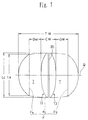
- the circumferential groove forms widened parts as shown in Fig. 7 at the front and the back of a ground-contacting centre Q, when the tyre comes in contact with the ground. Then, these widened parts prevent the columnar resonance and reduce the tyre noise effectively.
- the convex form of the central part contributes to heightening of stiffness of the central part, and since the ground-contacting length Lc of the central part is in a range of 0.9 to 1.1 times the ground-contacting length Ls of the shoulder part, the steering stability is enhanced, and the ground-contacting performance in a limited ground-contacting width is improved.
- the tyre 1 comprises a pair of bead parts B each having a bead core 2, sidewall parts S extending from the bead parts B outwardly in the radial direction of tyre, and a tread part T linking their outer ends.
- a radial carcass 3 extends between the bead parts B.
- the edges of the carcass 3 are folded back from inside to outside one around the bead core 2, and a belt layer 4 is provided above the carcass 3 and radially inwards of the tread part T.
- a rubber bead apex 6 extending radially outward from each bead core 2 is provided between the main part of the carcass 3 and the folded back part thereof so as to maintain the shape and rigidity of the bead part B.
- the belt layer 4 comprises plural belt plies of cords aligned at an angle of 15 to 30 degrees to the tyre equator CL and coated by a topping rubber.
- the belt cords have a high tensile strength, such as steel or aromatic polyamide, and are arranged to cross to each other between the belt plies.
- a high tensile strength such as steel or aromatic polyamide
- organic fibre cords such as nylon, rayon or polyester may be generally employed.
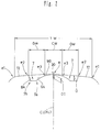
- the tread part T has two wide circumferential grooves 7, which are positioned one at either side of the tyre's equator CL and which continuously extend substantially in the circumferential direction, so that the tread part T is divided into a pair of shoulder parts 8 and a central part 9.
- Each shoulder part 8 is defined as the region outside an outer bottom edge 7b of the circumferential groove 7 in the axial direction of tyre.
- the central part 9 is defined as the region between the inner bottom edges 7a, 7a of the circumferential grooves 7 in the axial direction of tyre.
- the circumferential grooves 7 are positioned symmetrically about the tyre's equatorial surface.
- the two circumferential grooves 7 have the same groove depth D to each other, and this groove depth D is set in a range of 4 to 8% of the ground-contacting width TW of the tread such as 7.5 to 15.0 mm, preferably 8.4 mm for a tyre of 205/55R15 in size.
- the central part 9 has a surface with a smooth convex curve composed of a pair of inner groove walls 9A extending inwards in the axial direction of the tyre along a curve convexed outwardly in the radial direction of tyre from the inner bottom edges 7a of the grooves 7 and a central ground-contacting surface 9B smoothly connected between the inner groove walls 9A, 9A.
- a ground-contacting tread area F is obtained shown by the broken lines where the tread T contacts with the ground.
- the ground-contacting tread area F has a ground-contacting area Fc for the central part 9 having a thin elliptic form and two ground-contacting areas Fs for the shoulder parts 8 each having a semicircular form.
- the central ground-contacting surface 9B is defined as the part of the tread surface between the circumferential lines e3, e3 passing through the axially outer edges of the ground-contacting area Fc.
- the shoulder ground-contacting surface 12 is defined as the part of the tread surface between the circumferential lines e1, e2 passing through the axially outer and inner edges of the ground-contacting area Fs.
- the ground-contacting width TW is defined as an axially length between the circumferental lines e1, e1.
- the shoulder ground-contacting surface 12 is also crossed by an outer groove wall 8a extending radially outwards from the outer bottom edge 7b of the groove 7, thus, the circumferential groove 7 is defined by the groove bottom 7S and inner and outer groove wall 9A, 8A.
- the groove width GW of the circumferential groove 7 is defined as the axial length between the circumferential lines e2, e3.
- the groove bottom edges 7a, 7b may be formed, when the groove bottom 7S is approximately a flat surface as in the embodiment, as bending points between the groove bottom 7S and groove walls 8A, 9A.
- the groove bottom 7S is a concave surface as shown in Figs. 3(A) and 3(B)
- the groove bottom edges 7a, 7b may be formed as bending points or inflection points.
- the central ground-contacting surface 9B is substantially in contacting with a virtual tread line 10 connecting between the shoulder ground-contacting surfaces 12.
- the expression “substantially in contact” means that the minimum distance L between the central ground-contacting surface 9B and the virtual tread line 10 is within 2% of the ground-contacting tread width TW. If it is 2% or more, because the difference between the ground-contacting pressures of the shoulder part and central part is increased, the grip performance is reduced, and the wear resistance is affected. Thus, it should be preferably 1% or less, more preferably 0.5% or less.
- the virtual tread line 10 is defined as the arcuate curve of a single radius of curvature which extends between the axially inner edges Ea, Ea of the shoulder ground-contacting surfaces 12 and is in contact with tangent lines to the shoulder ground-contacting surfaces 12 at the axially inner edges Ea thereof.
- the virtual tread line 10 is formed as a straight line connecting between the inner edges Ea, Ea.
- the convex central part 9 provides a sub-tread having a radius of curvature which is comparatively small and a width sufficiently narrower than the tyre's width in the centre of tyre, thus, the hydroplaning phenomenon is prevented, and the wet grip performance is increased.
- the radius of curvature R2 of the shoulder ground-contacting surface 12 should be comparatively large, preferably 3 or more times the ground-contacting width TW. It is also allowable for the shoulder ground-contacting surface 12 to be approximately a straight line parallel to the tyre's axis.
- Figs. 1 and 2 show an example with the surface of the central part 9 formed by an arc with a radius of curvature R1.
- the radius of curvature R1 is substantially smaller than the radius of curvature R2 of the shoulder part 8, and the convex curve of the central part 9 is inscribed with the virtual tread line 10 in the example.
- the distance L is drawn on purpose to explain the phrase "substantially in contact”.
- the radius of curvature R1 is set within a range of 0.4 to 1.5 times, more preferably 0.45 to 0.55 times the ground-contacting tread width TW. If it is less than 0.4 times, the width CW of the central ground-contacting surface 9B is too small, and the dry grip performance tends to be significantly reduced. If it is more than 1.5 times, the draining effect is insufficient, and the wet grip performance is inferior.
- both radii of curvature R1, R2 have their centres on the tyre's equatorial surface, and the shoulder part 8 is provided with an arcuate part with a radius of curvature smaller than the radius of curvature R2 in the vicinity of the axially outer edge of the ground-contacting tread area F.
- the outer groove wall 8A of the groove 7 is formed by a relatively steep and non-arcuate line such as a straight line, at an angle ⁇ of 0 to 40 degrees, preferably 5 to 25 degrees to a radial line X, so that an edge effect on a road surface is provided at the inner edge Ea of the shoulder part 8 with a high ground-contacting pressure to help maintain the dry grip performance by increasing lateral force, and thereby cornering power.
- the outer groove wall 8A may be formed as a convex curve similar to the inner groove wall 9A, or extended in a zigzag, as shown in Fig. 14, to increase traction.
- a total groove width ratio 2GW/TW of the groove width 2GW of the circumferential grooves 7 to the ground-contact tread width TW affects the cornering power and wet grip performance.
- Fig. 5 shows the result of measuring the cornering power of a tyre 205/55 R15 in size with a central part in the form of a single arc as shown in Fig. 1 and a conventional tyre with four circumferential grooves G as shown in Fig. 15 by changing the total groove width ratio ⁇ GW/TW.
- the value of the ratio 2GW/TW was employed for the embodiment, and the value of the ratio ( ⁇ GW)/TW for the conventional example.
- the cornering power was measured on a drum tester in the normal state. It was shown that the embodiment shows a higher value in comparison with the conventional tyre. This is considered to be because, when the total groove width ratio defined as above is constant, the inner groove wall 9A of the convex curve contributes to increasing the tyre's lateral rigidity.
- Fig. 6 shows the result of measuring, in a similar manner, the hydroplaning inducing speed. It was shown that the hydroplaning phenomenon occurred at a higher speed in the embodiment, compared to the conventional tyre. This is considered to be because the circumferential groove 7 forms a widened part 13 as shown in Fig. 7 at the front and the back of the ground-contacting centre Q, when the tyre comes in contact with the ground.
- the widened part 13 increases the draining performance.
- the value of the ratio ( ⁇ GW)/TW is preferably less than 50%, more preferably less than 45%.
- the widened part 13 prevents occurrence of the columnar resonance in the circumferential groove 7, thereby there is a reduction in tyre noise.
- the groove width GW of the circumferential groove 7 must be 35 mm or more, preferably 40 mm or more. It is known from the result in Fig. 8 showing the measurement of pass-by noise for different groove widths GW at a fixed groove depth of the circumferential groove 7. As shown in Fig. 8, the pass-by noise reaches a peak at a groove width GW of 25 mm, and then drops suddenly, and an excellent low noise characteristic is noted at 35 mm and over. Nevertheless, although the tyre of the invention has a high cornering power as shown in Fig. 5, the increase in the groove width GW causes a decrease in the ground contact area, and then the balance of the ground-contacting stability tends to be lost, thereby lowering steering stability.
- the length Lc of the ground-contacting area Fc in the circumferential direction is defined at 0.9 or more times the length Ls of the ground-contacting area Fs in the circumferential direction as shown in Fig. 7.
- the length Lc of the ground-contacting area Fc of the central part 9 is increased, the directional stability is enhanced, and the ground-contacting performance in a limited ground-contacting width is improved, so that the steering stability may be upgraded.
- the length Lc should be 0.9 to 1.1 times the length Ls.
- This embodiment relates to a symmetrical tread profile having the same groove width GW in the right and left circumferential grooves 7, but it may be asymmetrical by varying the groove width GW, or, as shown in Fig. 9, the central plane KL of the central part 9 may be deviated to a position remote from the equatorial plane of the tyre.
- the surface of the central part 9 is formed by a single arc in the embodiment shown in Fig. 1, it may be formed in an elliptic shape, as shown in Fig. 10, or a curve approximating to an ellipse.
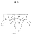
- Fig. 11 shows that the groove wall 9A and the central ground-contacting surface 9B have different radii of curvature R3, R4.
- the radius of curvature R3 is less than the radius of curvature R4 of the central ground-contacting surface 9B and the radius of curvature R2 of the shoulder ground-contacting surface 12, respectively, and the lower limit thereof is preferably 5% or more of the ground-contacting tread width TW. If it is less than 5%, the draining effect tends to be insufficient.
- the higher limit is at a value identical to the radius of curvature R4, and then the central surface is formed by a single arc.
- the radius of curvature R4 can be close to the radius of curvature R2 as far as the wet grip performance is not inferior.
- the radius of the central ground-contacting surface 9B becomes relatively greater.
- the shape of the ground-contacting area Fc approximates to a rectangle, as shown in Fig. 12, thereby increasing the ground-contacting area and improving wear durability and steering stability.
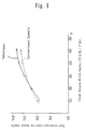
- the central part 9 is provided with radiation grooves 21 heat release as shown in Fig. 4.
- the radiation grooves 21 comprise, in the embodiment, a circumferential radiation groove 20 and a lateral radiation groove 22.
- the circumferential radiation groove 20 is formed as a narrow groove extending continuously substantially along the central plane KL.
- the radiation groove 20 is capable of maintaining the pattern rigidity, while providing a heat radiation effect, by setting the groove depth D1 thereof at 0.4 to 0.9 times the groove depth D of the circumferential groove 7, and the groove width W1 at 5 mm or less. If the groove width W1 is more than 5 mm, and the groove depth D1 is more than 0.9 times the groove depth D, then columnar resonance is caused. If the groove depth D1 is less than 0.4 times the groove depth D, the heat radiation effect is insufficient.
- the lateral radiation groove 22 extends from an inner end spaced from the circumferential radiation groove 20 towards the outside in the axial direction of tyre at an inclination ⁇ of 10 degrees or more to the axial direction of tyre, and has an outer end thereof open into the circumferential groove 7.
- the groove depth D2 of the lateral radiation groove 22 is also 0.4 to 0.9 times the groove depth D. If the groove depth D2 is more than 0.9 times the groove depth D, and the inclination ⁇ is less than 10 degrees, then the pitch noise of the lateral radiation groove 22 is excessively high. If the groove depth D2 is less than 0.4 times the groove depth D, a sufficient heat radiation effect cannot be expected.
- the angle subtended by the groove walls and the normal to the tread surface that is, the inclination gradient of the groove walls is set at 15 degrees or less, more preferably 5 degrees or less, respectively, and thus dimensional change of the radiation grooves 21 as the tyre wears is thereby very limited.
- a shoulder groove 23 is additionally formed in the shoulder part 8.
- Each shoulder groove 23 is an open groove with an inner end thereof open to the circumferential groove 7 and the outer end to the tread edge.
- An average pitch length of a lateral groove in the circumferential direction of tyre is generally about 30 mm, and the resultant primary frequency at a speed of 60 km/h, for example, is 500 to 600 Hz, thus, showing a coincidence with a frequency of noise peak in a tyre with a tread profile having the convex central part 9, as shown in Fig. 13. Therefore, in the embodiment, the average pitch length P1 of the lateral radiation grooves 22 and the average pitch length P2 of the shoulder grooves 23 are preferably set at 40 mm or more, respectively, so that the primary pitch frequencies of the grooves 22, 23 are both different from the noise peak.
- Fig. 14 shows another example of radiation grooves 21 and circumferential grooves 7.
- the groove walls of the circumferential radiation grooves 20 and the groove wall 8A of the circumferential groove 7 may be formed as a zigzag.
- a tyre of 205/55 R15 in size was produced according to specifications shown in Table 1, and measured for steering stability and wear durability. The results of the measurements are shown in the Table.
- the test tyres had the same tread profile, and the balance between the lengths Lc, Ls was changed by changing the width of the belt layer 4, the angle of the belt cords or constructions of bandage layer provided on the belt layer 4.
- the tyres were tested and measured mounted on its regular rim R and inflated with regular internal pressure (2.4 kg/cm 2 ) and with the with normal load (450 kg) applied.
Description
- The present invention relates to a pneumatic tyre, particularly a low aspect radial tyre for passenger vehicles, capable of providing higher wet grip performance and reduction of tyre noise and maintaining steering stability.
- Recently, as automobiles become quieter tyre noise has come to contribute a higher ratio of the total noise level of an automobile, and its reduction is demanded. Such noise reduction is specifically desired in a range around 1 kHz from the peak frequency of tyre noise, and sounds due to a columnar resonance generated by circumferential grooves is one of the main sound sources in such a frequency range.
- On the other hand, in order to maintain the wet grip performance, the tread of a tyre is generally provided with plural circumferential grooves continuously extending in the circumferential direction of tyre.
- In such a tyre, when it is in contact with the ground, a kind of air column is formed by the road surface and the circumferential groove. Then a sound of a specific wavelength, which is double the wave length of the air column is caused by airflow within the column during running.
- Such a phenomenon is referred to as the columnar resonance, and provides the main source of noise at 800 Hz to 1.2 kHz. The wavelength of the columnar resonance sound is approximately constant to give a constant frequency regardless of the tyre's speed, and this increases sound inside and outside an automobile. Incidentally, since this noise around 1 kHz is a sound easily heard by a human ear, the increase of noise with such a frequency range influences the tyre noise performance greatly.
- In order to prevent the columnar resonance, although reduction of the number or volume of the circumferential grooves is known, such reductions lead to a lower wet grip performance.
- On the other hand, although the wet grip performance can be increased contrarily by increasing the number or volume of circumferential grooves, a simple increase causes reduction of the dry grip performance, because the ground-contact area is reduced. Also, this causes a reduction of steering stability as the rigidity of the tread pattern is reduced, in addition to the increase in tyre noise. Conventionally, a tyre's performance has been adjusted by sacrificing one or more performances factors.
- EP-A-0 593 288, document falling under Art. 54(3), shows a similar tyre in which the ratio Lc/Ls of central to shoulder lengths of the footprint is greater than 1.
- It is hence a primary object of the invention to provide a pneumatic tyre having improved wet grip performance without loss of dry grip performance or steering stability, and yet having reduced noise.
- According to the present invention, a pneumatic tyre comprises a tread part having two circumferential grooves continuously extending in the circumferential direction on either side of the tyre's equator so as to divide the tread part into a pair of shoulder parts, which are located outside outer bottom edges of the circumferential grooves in the axial direction of tyre, and a central part, which is located between inner bottom edges of the circumferential grooves in the axial direction of tyre, characterised in that the central part has a surface comprising successive convex curves composed of a pair of inner groove walls extending inwards, in the axial direction of tyre, along a curve convex outwardly in the radial direction from the inner bottom edges of the circumferential grooves and a central ground-contacting surface smoothly connected between the pair of the inner groove walls, the central ground-contacting surface is substantially in contact with a virtual tread line between outer surfaces of the shoulder parts, and when the tyre is mounted on a regular rim, inflated to its regular internal pressure and has applied its normal load, a ground-contacting area Fc where the central part contacts the ground has a length Lc in the tyre's circumferential direction which is 0.9 to 0.96 times a length Ls in the tyre's circumferential direction of a ground-contacting area FS where the shoulder part contacts the ground.
- In the invention, as the groove depth of the circumferential groove is gradually increased toward the outside in the tyre's axial direction because of the surface of the central part formed by a convex curve, the draining performance is increased, thereby improving the wet grip performance. The circumferential groove, also, forms widened parts as shown in Fig. 7 at the front and the back of a ground-contacting centre Q, when the tyre comes in contact with the ground. Then, these widened parts prevent the columnar resonance and reduce the tyre noise effectively. In addition, the convex form of the central part contributes to heightening of stiffness of the central part, and since the ground-contacting length Lc of the central part is in a range of 0.9 to 1.1 times the ground-contacting length Ls of the shoulder part, the steering stability is enhanced, and the ground-contacting performance in a limited ground-contacting width is improved.
- An embodiment of the present invention will now be described, by way of example, referring to the attached diagrammatic drawings, in which:
- Fig. 1 is a sectional view showing an embodiment of the invention;
- Fig. 2 is a enlarged sectional view showing the configuration of the a central part;
- Fig. 3(A) is an enlarged partial sectional view for explanation of the groove bottom ends;
- Fig. 3(B) is another enlarged partial sectional view for explanation of the groove bottom ends;
- Fig. 4 is a partial flat view showing a tread pattern;
- Fig. 5 is a diagram showing the relation between the total groove width ratio and cornering power;
- Fig. 6 is a graph showing the relation between the total groove width ratio and hydroplaning-inducing speed;
- Fig. 7 is a plan view showing the ground-contacting tread area of an embodiment of the invention when a normal load is applied;
- Fig. 8 is a diagram showing the result of a noise test;
- Fig. 9 is a sectional view of a tyre showing another example of a central part configuration;
- Fig. 10 is a sectional view of a tyre showing still another example of a central part configuration;
- Fig. 11 is a sectional view of a tyre showing yet another example of a central part configuration;
- Fig. 12 is a plan view showing the typical ground-contacting tread area of the tyre in Fig.10 and 11;
- Fig. 13 is a graph showing the result of a frequency analysis of tyre noise for an embodiment of the invention;
- Fig. 14 is a partial flat view of a tread pattern showing another example of circumferential grooves and circumferential radiation grooves; and
- Fig. 15 is a sectional view showing a tread profile of a conventional tyre.
- The
tyre 1 comprises a pair of bead parts B each having abead core 2, sidewall parts S extending from the bead parts B outwardly in the radial direction of tyre, and a tread part T linking their outer ends. The aspect ratio is between 0.4 and 0.6 to provide a low aspect tyre for passenger vehicles.
- A
radial carcass 3 extends between the bead parts B. The edges of thecarcass 3 are folded back from inside to outside one around thebead core 2, and a belt layer 4 is provided above thecarcass 3 and radially inwards of the tread part T.
In addition, arubber bead apex 6 extending radially outward from eachbead core 2 is provided between the main part of thecarcass 3 and the folded back part thereof so as to maintain the shape and rigidity of the bead part B. - The belt layer 4 comprises plural belt plies of cords aligned at an angle of 15 to 30 degrees to the tyre equator CL and coated by a topping rubber. The belt cords have a high tensile strength, such as steel or aromatic polyamide, and are arranged to cross to each other between the belt plies. For the carcass cords, in the case of a tyre for passenger vehicles, such organic fibre cords as nylon, rayon or polyester may be generally employed.
- The tread part T has two wide
circumferential grooves 7, which are positioned one at either side of the tyre's equator CL and which continuously extend substantially in the circumferential direction, so that the tread part T is divided into a pair ofshoulder parts 8 and acentral part 9. Eachshoulder part 8 is defined as the region outside anouter bottom edge 7b of thecircumferential groove 7 in the axial direction of tyre. Thecentral part 9 is defined as the region between theinner bottom edges circumferential grooves 7 in the axial direction of tyre. Thecircumferential grooves 7 are positioned symmetrically about the tyre's equatorial surface. The twocircumferential grooves 7 have the same groove depth D to each other, and this groove depth D is set in a range of 4 to 8% of the ground-contacting width TW of the tread such as 7.5 to 15.0 mm, preferably 8.4 mm for a tyre of 205/55R15 in size. - The
central part 9 has a surface with a smooth convex curve composed of a pair ofinner groove walls 9A extending inwards in the axial direction of the tyre along a curve convexed outwardly in the radial direction of tyre from theinner bottom edges 7a of thegrooves 7 and a central ground-contactingsurface 9B smoothly connected between theinner groove walls - Incidentally, when a normal load is applied to the tyre in the normal state, as shown in Fig. 4, a ground-contacting tread area F is obtained shown by the broken lines where the tread T contacts with the ground. The ground-contacting tread area F has a ground-contacting area Fc for the
central part 9 having a thin elliptic form and two ground-contacting areas Fs for theshoulder parts 8 each having a semicircular form. Then, the central ground-contactingsurface 9B is defined as the part of the tread surface between the circumferential lines e3, e3 passing through the axially outer edges of the ground-contacting area Fc. The shoulder ground-contactingsurface 12 is defined as the part of the tread surface between the circumferential lines e1, e2 passing through the axially outer and inner edges of the ground-contacting area Fs. The ground-contacting width TW is defined as an axially length between the circumferental lines e1, e1. The shoulder ground-contactingsurface 12 is also crossed by an outer groove wall 8a extending radially outwards from theouter bottom edge 7b of thegroove 7, thus, thecircumferential groove 7 is defined by the groove bottom 7S and inner andouter groove wall circumferential groove 7 is defined as the axial length between the circumferential lines e2, e3. - The
groove bottom edges groove walls groove bottom edges - The central ground-contacting
surface 9B is substantially in contacting with avirtual tread line 10 connecting between the shoulder ground-contactingsurfaces 12. - Here, the expression "substantially in contact" means that the minimum distance L between the central ground-contacting
surface 9B and thevirtual tread line 10 is within 2% of the ground-contacting tread width TW. If it is 2% or more, because the difference between the ground-contacting pressures of the shoulder part and central part is increased, the grip performance is reduced, and the wear resistance is affected. Thus, it should be preferably 1% or less, more preferably 0.5% or less. - Additionally, the
virtual tread line 10 is defined as the arcuate curve of a single radius of curvature which extends between the axially inner edges Ea, Ea of the shoulder ground-contactingsurfaces 12 and is in contact with tangent lines to the shoulder ground-contactingsurfaces 12 at the axially inner edges Ea thereof. When the tangent is approximately parallel, thevirtual tread line 10 is formed as a straight line connecting between the inner edges Ea, Ea. - In the invention, the convex
central part 9 provides a sub-tread having a radius of curvature which is comparatively small and a width sufficiently narrower than the tyre's width in the centre of tyre, thus, the hydroplaning phenomenon is prevented, and the wet grip performance is increased. - By reducing the radius of curvature of the
central part 9, specifically that of the central ground-contactingsurface 9B, the water draining performance to the outside in both directions is increased, and the water clearing effect on a wet road is enhanced. - Incidentally, in the case where the radius of curvature R2 of the shoulder ground-contacting
surface 12 is also reduced, the grip performance on a dry road and steering stability in cornering are reduced due to a reduction of ground-contacting width. Therefore, the radius of curvature R2 of the shoulder ground-contactingsurface 12 should be comparatively large, preferably 3 or more times the ground-contacting width TW. It is also allowable for the shoulder ground-contactingsurface 12 to be approximately a straight line parallel to the tyre's axis. - Figs. 1 and 2 show an example with the surface of the
central part 9 formed by an arc with a radius of curvature R1. The radius of curvature R1 is substantially smaller than the radius of curvature R2 of theshoulder part 8, and the convex curve of thecentral part 9 is inscribed with thevirtual tread line 10 in the example. In Fig. 1, the distance L is drawn on purpose to explain the phrase "substantially in contact". - It is also preferable that the radius of curvature R1 is set within a range of 0.4 to 1.5 times, more preferably 0.45 to 0.55 times the ground-contacting tread width TW. If it is less than 0.4 times, the width CW of the central ground-contacting
surface 9B is too small, and the dry grip performance tends to be significantly reduced. If it is more than 1.5 times, the draining effect is insufficient, and the wet grip performance is inferior. In the embodiment, both radii of curvature R1, R2 have their centres on the tyre's equatorial surface, and theshoulder part 8 is provided with an arcuate part with a radius of curvature smaller than the radius of curvature R2 in the vicinity of the axially outer edge of the ground-contacting tread area F. - Furthermore, in the
shoulder part 8, it is desirable that theouter groove wall 8A of thegroove 7 is formed by a relatively steep and non-arcuate line such as a straight line, at an angle α of 0 to 40 degrees, preferably 5 to 25 degrees to a radial line X, so that an edge effect on a road surface is provided at the inner edge Ea of theshoulder part 8 with a high ground-contacting pressure to help maintain the dry grip performance by increasing lateral force, and thereby cornering power. Theouter groove wall 8A may be formed as a convex curve similar to theinner groove wall 9A, or extended in a zigzag, as shown in Fig. 14, to increase traction. - Regarding the
circumferential groove 7, it was found that a total groove width ratio 2GW/TW of the groove width 2GW of thecircumferential grooves 7 to the ground-contact tread width TW affects the cornering power and wet grip performance. Fig. 5 shows the result of measuring the cornering power of a tyre 205/55 R15 in size with a central part in the form of a single arc as shown in Fig. 1 and a conventional tyre with four circumferential grooves G as shown in Fig. 15 by changing the total groove width ratio ΣGW/TW. For the total groove width ratio, the value of the ratio 2GW/TW was employed for the embodiment, and the value of the ratio (ΣGW)/TW for the conventional example. The cornering power was measured on a drum tester in the normal state. It was shown that the embodiment shows a higher value in comparison with the conventional tyre. This is considered to be because, when the total groove width ratio defined as above is constant, theinner groove wall 9A of the convex curve contributes to increasing the tyre's lateral rigidity. - Fig. 6 shows the result of measuring, in a similar manner, the hydroplaning inducing speed. It was shown that the hydroplaning phenomenon occurred at a higher speed in the embodiment, compared to the conventional tyre. This is considered to be because the
circumferential groove 7 forms awidened part 13 as shown in Fig. 7 at the front and the back of the ground-contacting centre Q, when the tyre comes in contact with the ground. Thewidened part 13 increases the draining performance. Incidentally, in the case where the value of the ratio (ΣGW)/TW exceeds 50%, the increasing of the inhibitory effect of hydroplaning phenomenon is not expected as shown in Fig. 6, and the cornering power becomes insufficient. Therefore, the value of the ratio (ΣGW)/TW is preferably less than 50%, more preferably less than 45%. - Also, the
widened part 13 prevents occurrence of the columnar resonance in thecircumferential groove 7, thereby there is a reduction in tyre noise. - To further enhance the inhibitory effect of air column resonance, the groove width GW of the
circumferential groove 7 must be 35 mm or more, preferably 40 mm or more. It is known from the result in Fig. 8 showing the measurement of pass-by noise for different groove widths GW at a fixed groove depth of thecircumferential groove 7. As shown in Fig. 8, the pass-by noise reaches a peak at a groove width GW of 25 mm, and then drops suddenly, and an excellent low noise characteristic is noted at 35 mm and over. Nevertheless, although the tyre of the invention has a high cornering power as shown in Fig. 5, the increase in the groove width GW causes a decrease in the ground contact area, and then the balance of the ground-contacting stability tends to be lost, thereby lowering steering stability. - In the invention, therefore, in order to maintain a high steering stability while exhibiting low noise performance and hydroplaning resistance, the length Lc of the ground-contacting area Fc in the circumferential direction is defined at 0.9 or more times the length Ls of the ground-contacting area Fs in the circumferential direction as shown in Fig. 7. Thus, since the length Lc of the ground-contacting area Fc of the
central part 9 is increased, the directional stability is enhanced, and the ground-contacting performance in a limited ground-contacting width is improved, so that the steering stability may be upgraded. Meanwhile, if the length Lc is smaller than 0.9 times the length Ls, the steering stability is insufficient, and if exceeding 1.1 times, the steering stability is enhanced, but the wear rate in thecentral part 9 increases remarkably, and tyre life is shortened. Hence, the length Lc should be 0.9 to 1.1 times the length Ls. - This embodiment relates to a symmetrical tread profile having the same groove width GW in the right and left
circumferential grooves 7, but it may be asymmetrical by varying the groove width GW, or, as shown in Fig. 9, the central plane KL of thecentral part 9 may be deviated to a position remote from the equatorial plane of the tyre. - Incidentally, although the surface of the
central part 9 is formed by a single arc in the embodiment shown in Fig. 1, it may be formed in an elliptic shape, as shown in Fig. 10, or a curve approximating to an ellipse. - Fig. 11 shows that the
groove wall 9A and the central ground-contactingsurface 9B have different radii of curvature R3, R4. The radius of curvature R3 is less than the radius of curvature R4 of the central ground-contactingsurface 9B and the radius of curvature R2 of the shoulder ground-contactingsurface 12, respectively, and the lower limit thereof is preferably 5% or more of the ground-contacting tread width TW. If it is less than 5%, the draining effect tends to be insufficient. The higher limit is at a value identical to the radius of curvature R4, and then the central surface is formed by a single arc. The radius of curvature R4 can be close to the radius of curvature R2 as far as the wet grip performance is not inferior. - Incidentally, when the surface of the
central part 9 is formed in an elliptic shape, as shown in Fig. 10, or a curve approximating to an ellipse by a plurality of arcs, as shown in Fig. 11, the radius of the central ground-contactingsurface 9B becomes relatively greater. As a result, the shape of the ground-contacting area Fc approximates to a rectangle, as shown in Fig. 12, thereby increasing the ground-contacting area and improving wear durability and steering stability. - In the embodiment, also, the
central part 9 is provided withradiation grooves 21 heat release as shown in Fig. 4. Theradiation grooves 21 comprise, in the embodiment, acircumferential radiation groove 20 and alateral radiation groove 22. Thecircumferential radiation groove 20 is formed as a narrow groove extending continuously substantially along the central plane KL. Theradiation groove 20 is capable of maintaining the pattern rigidity, while providing a heat radiation effect, by setting the groove depth D1 thereof at 0.4 to 0.9 times the groove depth D of thecircumferential groove 7, and the groove width W1 at 5 mm or less. If the groove width W1 is more than 5 mm, and the groove depth D1 is more than 0.9 times the groove depth D, then columnar resonance is caused. If the groove depth D1 is less than 0.4 times the groove depth D, the heat radiation effect is insufficient. - The
lateral radiation groove 22 extends from an inner end spaced from thecircumferential radiation groove 20 towards the outside in the axial direction of tyre at an inclination θ of 10 degrees or more to the axial direction of tyre, and has an outer end thereof open into thecircumferential groove 7. - Thus, because the
lateral radiation groove 22 is spaced from thecircumferential radiation groove 20, the rigidity of thecentral part 9 is maintained, and the steering stability is assured. - The groove depth D2 of the
lateral radiation groove 22 is also 0.4 to 0.9 times the groove depth D. If the groove depth D2 is more than 0.9 times the groove depth D, and the inclination θ is less than 10 degrees, then the pitch noise of thelateral radiation groove 22 is excessively high. If the groove depth D2 is less than 0.4 times the groove depth D, a sufficient heat radiation effect cannot be expected. - In the circumferential and
lateral radiation grooves radiation grooves 21 as the tyre wears is thereby very limited. - In the embodiment, a
shoulder groove 23 is additionally formed in theshoulder part 8. Eachshoulder groove 23 is an open groove with an inner end thereof open to thecircumferential groove 7 and the outer end to the tread edge. Thus, by opening it to the circumferential groove, the heat radiation effect is further increased, increase of temperature in theshoulder groove 8 is significantly reduced, and the draining performance is enhanced. - An average pitch length of a lateral groove in the circumferential direction of tyre is generally about 30 mm, and the resultant primary frequency at a speed of 60 km/h, for example, is 500 to 600 Hz, thus, showing a coincidence with a frequency of noise peak in a tyre with a tread profile having the convex
central part 9, as shown in Fig. 13. Therefore, in the embodiment, the average pitch length P1 of thelateral radiation grooves 22 and the average pitch length P2 of theshoulder grooves 23 are preferably set at 40 mm or more, respectively, so that the primary pitch frequencies of thegrooves - Fig. 14 shows another example of
radiation grooves 21 andcircumferential grooves 7. The groove walls of thecircumferential radiation grooves 20 and thegroove wall 8A of thecircumferential groove 7 may be formed as a zigzag. - A tyre of 205/55 R15 in size was produced according to specifications shown in Table 1, and measured for steering stability and wear durability. The results of the measurements are shown in the Table. The test tyres had the same tread profile, and the balance between the lengths Lc, Ls was changed by changing the width of the belt layer 4, the angle of the belt cords or constructions of bandage layer provided on the belt layer 4. The tyres were tested and measured mounted on its regular rim R and inflated with regular internal pressure (2.4 kg/cm2) and with the with normal load (450 kg) applied.
[ Table 1 ] Embodiment Comparative 1 2 3 1 2 Tread Profile Fig.2 Fig.2 Fig.2 Fig.2 Fig.2 Groove Width GW(mm) 42 40 41 42 42 Ground-Contacting Tread Width TW(mm) 166 160 152 170 150 Length Lc(mm) 112 110 122 107 130 Length Ls(mm) 119 115 114 126 113 Ratio Lc/Ls 0.94 0.96 1.07 0.85 1.15 Steering Stability (∗1) 3 3∼3- 3- 3-∼2.5 3-∼2.5 Wear Durability of Central Part (∗2) 94 100 105 92 113 (∗1) Steering Stability was evaluated by the driver's feeling, and indicated as the index 5. The greater figure means the better performance. (∗2) Wear amount after driving was measured, and indicated as the index with the embodiment 2 taken as 100. The greater figure means the worse performance.
Claims (8)
- A pneumatic tyre comprising a tread part (T) having two circumferential grooves (7) continuously extending in the circumferential direction on either side of the tyre's equator (CL) so as to divide the tread part (T) into a pair of shoulder parts (8), which are located outside outer bottom edges (7b) of the circumferential grooves (7) in the axial direction of tyre, and a central part (9), which is located between inner bottom edges (7a) of the circumferential grooves (7) in the axial direction of tyre, characterised in that the central part (9) has a surface comprising successive convex curves composed of a pair of inner groove walls (9A) extending inwards, in the axial direction of tyre, along a curve convex outwardly in the radial direction from the inner bottom edges (7a) of the circumferential grooves (7) and a central ground-contacting surface (9B) smoothly connected between the pair of the inner groove walls (9A), the central ground-contacting surface (9) is substantially in contact with a virtual tread line (10) between outer surfaces (12) of the shoulder parts, and when the tyre is mounted on a regular rim, inflated to its regular internal pressure and has applied its normal load, a ground-contacting area Fc where the central part (9) contacts the ground having a length Lc in the tyre's circumferential direction which is 0.9 to 0.96 times a length Ls in the tyre's circumferential direction of a ground-contacting area FS where the shoulder part contacts the ground.
- A pneumatic tyre according to claim 1, characterised in that the circumferential grooves (7) have a groove width GW in a range of 35 mm or more.
- A pneumatic tyre according to claim 1 or 2, characterised in that the ground-contacting area Fc of the central part has an elliptic shape.
- A pneumatic tyre according to any of claims 1 to 3, characterised in that the ratio Lc/Ls of the length Lc to the length Ls is 0.94 to 0.96.
- A pneumatic tyre according to any of claims 1 to 3, characterised in that the ratio Lc/Ls of the length Lc to the length Ls is 0.94.
- A pneumatic tyre according to any of claims 1 to 5, characterised in that the surface of the central part (9) is composed of an arc of a single radius of curvature R1 being in a range of 0.45 to 0.55 times a ground-contact tread width TW.
- A pneumatic tyre according to any of claims 1 to 6, characterised in that the groove width GW of one of the circumferential grooves (7) differs from the groove width GW of the other of the circumferential grooves (7).
- A pneumatic tyre according to any of claims 1 to 7, characterised in that the central plane (KL) of the central part (9) is deviated to a position remote from the equatorial plane (CL) of the tyre.
Applications Claiming Priority (2)
| Application Number | Priority Date | Filing Date | Title |
|---|---|---|---|
| JP350822/93 | 1993-12-27 | ||
| JP5350822A JP2644970B2 (en) | 1993-12-27 | 1993-12-27 | Pneumatic tire |
Publications (2)
| Publication Number | Publication Date |
|---|---|
| EP0659593A1 EP0659593A1 (en) | 1995-06-28 |
| EP0659593B1 true EP0659593B1 (en) | 1997-09-24 |
Family
ID=18413121
Family Applications (1)
| Application Number | Title | Priority Date | Filing Date |
|---|---|---|---|
| EP94309583A Expired - Lifetime EP0659593B1 (en) | 1993-12-27 | 1994-12-20 | Pneumatic tyre |
Country Status (5)
| Country | Link |
|---|---|
| US (1) | US5688342A (en) |
| EP (1) | EP0659593B1 (en) |
| JP (1) | JP2644970B2 (en) |
| AU (1) | AU673967B2 (en) |
| DE (1) | DE69405848T2 (en) |
Cited By (1)
| Publication number | Priority date | Publication date | Assignee | Title |
|---|---|---|---|---|
| CN102666138A (en) * | 2009-12-25 | 2012-09-12 | 米其林企业总公司 | Pneumatic tire tread |
Families Citing this family (8)
| Publication number | Priority date | Publication date | Assignee | Title |
|---|---|---|---|---|
| US5957179A (en) * | 1993-11-03 | 1999-09-28 | The Goodyear Tire & Rubber Company | Pneumatic tire having improved wet traction |
| US6340041B1 (en) * | 1998-12-11 | 2002-01-22 | Sumitomo Rubber Industries | Pneumatic tire including two wide circumferential grooves |
| JP2006151308A (en) * | 2004-12-01 | 2006-06-15 | Bridgestone Corp | Pneumatic radial tire |
| US7780891B2 (en) * | 2007-05-25 | 2010-08-24 | Bridgestone Americas Tire Operations, Llc | Elliptical tire mold and method for making same |
| JP4813436B2 (en) * | 2007-09-12 | 2011-11-09 | 株式会社ブリヂストン | Pneumatic tire |
| JP5294735B2 (en) * | 2008-07-03 | 2013-09-18 | 株式会社ブリヂストン | Pneumatic tire |
| JP6438768B2 (en) * | 2012-11-30 | 2018-12-19 | 株式会社ブリヂストン | Pneumatic tire |
| JP6425531B2 (en) * | 2013-12-13 | 2018-11-21 | 株式会社ブリヂストン | Pneumatic tire |
Family Cites Families (36)
| Publication number | Priority date | Publication date | Assignee | Title |
|---|---|---|---|---|
| US1664352A (en) * | 1925-02-03 | 1928-03-27 | Coleman Edward William | Wheel tire |
| BE342141A (en) * | 1926-05-19 | |||
| BE384271A (en) * | 1930-11-20 | |||
| GB1255952A (en) * | 1968-01-12 | 1971-12-08 | Dunlop Holdings Ltd | Improvements in or relating to pneumatic tyres |
| JPS533124B2 (en) * | 1974-10-23 | 1978-02-03 | ||
| JPS5850883B2 (en) * | 1979-12-31 | 1983-11-12 | 東洋ゴム工業株式会社 | A pneumatic tire with a tread made of at least two types of rubber |
| JPS6127707A (en) * | 1984-07-17 | 1986-02-07 | Bridgestone Corp | Pneumatic tire for two-wheeled vehicle |
| GB2178380B (en) * | 1985-06-21 | 1989-07-12 | Bridgestone Corp | Pneumatic tire |
| JPH06102401B2 (en) * | 1986-09-30 | 1994-12-14 | 横浜ゴム株式会社 | Pneumatic radial tires |
| DE3643046A1 (en) * | 1986-12-17 | 1988-06-30 | Uniroyal Englebert Gmbh | Pneumatic vehicle tyre |
| JPS63162308A (en) * | 1986-12-26 | 1988-07-05 | Bridgestone Corp | Flat pneumatic radial tire used for high-speed running purpose |
| EP0323519B1 (en) * | 1987-07-08 | 1993-05-19 | Sumitomo Rubber Industries, Co. Ltd | Pneumatic tire |
| US5042546A (en) * | 1987-11-16 | 1991-08-27 | The Goodyear Tire & Rubber Company | Radial ply pneumatic tire with reverse curvature carcass ply |
| JP2650040B2 (en) * | 1988-04-28 | 1997-09-03 | 横浜ゴム株式会社 | Pneumatic tires for passenger cars |
| DE3824898A1 (en) * | 1988-07-22 | 1990-01-25 | Uniroyal Englebert Gmbh | VEHICLE TIRES |
| JPH0245203A (en) * | 1988-08-06 | 1990-02-15 | Bridgestone Corp | Pneumatic tire |
| USD330882S (en) | 1988-11-21 | 1992-11-10 | Sumitomo Rubber Industries, Ltd. | Automobile tire |
| JPH02182505A (en) * | 1989-01-08 | 1990-07-17 | Toyo Tire & Rubber Co Ltd | Tread pattern of automotive tire |
| JPH02267003A (en) * | 1989-04-07 | 1990-10-31 | Yokohama Rubber Co Ltd:The | Pneumatic tire |
| JP2790660B2 (en) * | 1989-07-05 | 1998-08-27 | 株式会社ブリヂストン | Floating vehicle tires |
| JPH0374208A (en) * | 1989-08-16 | 1991-03-28 | Yokohama Rubber Co Ltd:The | Pneumatic tire for automobile |
| JP2824672B2 (en) * | 1989-08-25 | 1998-11-11 | 横浜ゴム株式会社 | Pneumatic tire |
| DE69005784T2 (en) * | 1989-10-19 | 1994-04-28 | Sumitomo Rubber Ind | Radial pneumatic tire. |
| JP2844581B2 (en) * | 1989-10-19 | 1999-01-06 | 住友ゴム工業 株式会社 | Pneumatic radial tire |
| JPH03169719A (en) * | 1989-11-30 | 1991-07-23 | Sumitomo Rubber Ind Ltd | Pneumatic tire |
| JPH03204307A (en) * | 1989-12-29 | 1991-09-05 | Sumitomo Rubber Ind Ltd | Radial tire for passenger car |
| JP3001220B2 (en) * | 1990-02-23 | 2000-01-24 | 株式会社ブリヂストン | Pneumatic tire |
| JP3064345B2 (en) * | 1990-07-24 | 2000-07-12 | 株式会社ブリヂストン | Aircraft tires |
| JP2544528B2 (en) * | 1991-02-15 | 1996-10-16 | 住友ゴム工業株式会社 | High speed heavy duty tire |
| US5327952A (en) * | 1991-03-08 | 1994-07-12 | The Goodyear Tire & Rubber Company | Pneumatic tire having improved wet traction |
| US5337815A (en) * | 1992-10-05 | 1994-08-16 | The Goodyear Tire & Rubber Company | Pneumatic tire having improved wet traction |
| US5595619A (en) * | 1992-10-14 | 1997-01-21 | Sumitomo Rubber Industries, Ltd. | Pneumatic tire including shoulder parts |
| EP0593288B1 (en) * | 1992-10-14 | 1995-12-20 | Sumitomo Rubber Industries Limited | Pneumatic tyre |
| JPH06183208A (en) * | 1992-12-17 | 1994-07-05 | Ohtsu Tire & Rubber Co Ltd :The | Pneumatic tire |
| US5323824A (en) * | 1993-03-11 | 1994-06-28 | The Goodyear Tire & Rubber Company | Tire/vehicle system |
| JP3038408U (en) | 1996-08-06 | 1997-06-20 | 始 染矢 | Shaft with bicycle saddle receiving spring |
-
1993
- 1993-12-27 JP JP5350822A patent/JP2644970B2/en not_active Expired - Fee Related
-
1994
- 1994-12-20 EP EP94309583A patent/EP0659593B1/en not_active Expired - Lifetime
- 1994-12-20 DE DE69405848T patent/DE69405848T2/en not_active Expired - Fee Related
- 1994-12-23 AU AU81754/94A patent/AU673967B2/en not_active Ceased
- 1994-12-27 US US08/363,822 patent/US5688342A/en not_active Expired - Fee Related
Cited By (2)
| Publication number | Priority date | Publication date | Assignee | Title |
|---|---|---|---|---|
| CN102666138A (en) * | 2009-12-25 | 2012-09-12 | 米其林企业总公司 | Pneumatic tire tread |
| CN102666138B (en) * | 2009-12-25 | 2015-01-07 | 米其林企业总公司 | Pneumatic tire tread |
Also Published As
| Publication number | Publication date |
|---|---|
| DE69405848T2 (en) | 1998-01-15 |
| DE69405848D1 (en) | 1997-10-30 |
| JP2644970B2 (en) | 1997-08-25 |
| EP0659593A1 (en) | 1995-06-28 |
| JPH07186628A (en) | 1995-07-25 |
| AU8175494A (en) | 1995-07-06 |
| AU673967B2 (en) | 1996-11-28 |
| US5688342A (en) | 1997-11-18 |
Similar Documents
| Publication | Publication Date | Title |
|---|---|---|
| EP2281698B1 (en) | Pneumatic tire | |
| EP0593288B1 (en) | Pneumatic tyre | |
| EP0680837B1 (en) | Pneumatic tyre | |
| JP3515232B2 (en) | Pneumatic tire and method of using the same | |
| EP0640497B1 (en) | Pneumatic tyre | |
| EP0733498B1 (en) | Pneumatic tyre | |
| US6340041B1 (en) | Pneumatic tire including two wide circumferential grooves | |
| EP0728599B1 (en) | Pneumatic tyre | |
| EP0659593B1 (en) | Pneumatic tyre | |
| EP0676305B1 (en) | Pneumatic tyre | |
| EP3744536B1 (en) | Tyre | |
| EP3552846B1 (en) | Tyre | |
| EP0678403B1 (en) | Pneumatic tyre | |
| US5595619A (en) | Pneumatic tire including shoulder parts | |
| EP0791487B1 (en) | Pneumatic tyre | |
| EP0662397B1 (en) | Pneumatic tyre | |
| JP2992454B2 (en) | Pneumatic tire | |
| JPH0747808A (en) | Pneumatic tire | |
| JP2866596B2 (en) | Pneumatic tire | |
| EP3695986B1 (en) | Tyre |
Legal Events
| Date | Code | Title | Description |
|---|---|---|---|
| PUAI | Public reference made under article 153(3) epc to a published international application that has entered the european phase |
Free format text: ORIGINAL CODE: 0009012 |
|
| AK | Designated contracting states |
Kind code of ref document: A1 Designated state(s): DE FR GB IT |
|
| 17P | Request for examination filed |
Effective date: 19950808 |
|
| 17Q | First examination report despatched |
Effective date: 19960603 |
|
| GRAG | Despatch of communication of intention to grant |
Free format text: ORIGINAL CODE: EPIDOS AGRA |
|
| GRAH | Despatch of communication of intention to grant a patent |
Free format text: ORIGINAL CODE: EPIDOS IGRA |
|
| GRAH | Despatch of communication of intention to grant a patent |
Free format text: ORIGINAL CODE: EPIDOS IGRA |
|
| GRAA | (expected) grant |
Free format text: ORIGINAL CODE: 0009210 |
|
| AK | Designated contracting states |
Kind code of ref document: B1 Designated state(s): DE FR GB IT |
|
| ITF | It: translation for a ep patent filed |
Owner name: ING. C. GREGORJ S.P.A. |
|
| REF | Corresponds to: |
Ref document number: 69405848 Country of ref document: DE Date of ref document: 19971030 |
|
| ET | Fr: translation filed | ||
| PLBE | No opposition filed within time limit |
Free format text: ORIGINAL CODE: 0009261 |
|
| STAA | Information on the status of an ep patent application or granted ep patent |
Free format text: STATUS: NO OPPOSITION FILED WITHIN TIME LIMIT |
|
| 26N | No opposition filed | ||
| REG | Reference to a national code |
Ref country code: GB Ref legal event code: IF02 |
|
| PGFP | Annual fee paid to national office [announced via postgrant information from national office to epo] |
Ref country code: GB Payment date: 20031217 Year of fee payment: 10 |
|
| PG25 | Lapsed in a contracting state [announced via postgrant information from national office to epo] |
Ref country code: GB Free format text: LAPSE BECAUSE OF NON-PAYMENT OF DUE FEES Effective date: 20041220 |
|
| GBPC | Gb: european patent ceased through non-payment of renewal fee |
Effective date: 20041220 |
|
| PGFP | Annual fee paid to national office [announced via postgrant information from national office to epo] |
Ref country code: FR Payment date: 20051208 Year of fee payment: 12 |
|
| PG25 | Lapsed in a contracting state [announced via postgrant information from national office to epo] |
Ref country code: IT Free format text: LAPSE BECAUSE OF NON-PAYMENT OF DUE FEES;WARNING: LAPSES OF ITALIAN PATENTS WITH EFFECTIVE DATE BEFORE 2007 MAY HAVE OCCURRED AT ANY TIME BEFORE 2007. THE CORRECT EFFECTIVE DATE MAY BE DIFFERENT FROM THE ONE RECORDED. Effective date: 20051220 |
|
| PGFP | Annual fee paid to national office [announced via postgrant information from national office to epo] |
Ref country code: DE Payment date: 20061214 Year of fee payment: 13 |
|
| REG | Reference to a national code |
Ref country code: FR Ref legal event code: ST Effective date: 20070831 |
|
| PG25 | Lapsed in a contracting state [announced via postgrant information from national office to epo] |
Ref country code: FR Free format text: LAPSE BECAUSE OF NON-PAYMENT OF DUE FEES Effective date: 20070102 |
|
| PG25 | Lapsed in a contracting state [announced via postgrant information from national office to epo] |
Ref country code: DE Free format text: LAPSE BECAUSE OF NON-PAYMENT OF DUE FEES Effective date: 20080701 |