EP0659029A2 - Loudspeaker selection device - Google Patents
Loudspeaker selection device Download PDFInfo
- Publication number
- EP0659029A2 EP0659029A2 EP94119808A EP94119808A EP0659029A2 EP 0659029 A2 EP0659029 A2 EP 0659029A2 EP 94119808 A EP94119808 A EP 94119808A EP 94119808 A EP94119808 A EP 94119808A EP 0659029 A2 EP0659029 A2 EP 0659029A2
- Authority
- EP
- European Patent Office
- Prior art keywords
- loudspeaker
- radio
- audio device
- motor vehicle
- speaker
- Prior art date
- Legal status (The legal status is an assumption and is not a legal conclusion. Google has not performed a legal analysis and makes no representation as to the accuracy of the status listed.)
- Granted
Links
Images

Classifications
-
- H—ELECTRICITY
- H04—ELECTRIC COMMUNICATION TECHNIQUE
- H04R—LOUDSPEAKERS, MICROPHONES, GRAMOPHONE PICK-UPS OR LIKE ACOUSTIC ELECTROMECHANICAL TRANSDUCERS; DEAF-AID SETS; PUBLIC ADDRESS SYSTEMS
- H04R3/00—Circuits for transducers, loudspeakers or microphones
- H04R3/12—Circuits for transducers, loudspeakers or microphones for distributing signals to two or more loudspeakers
-
- H—ELECTRICITY
- H04—ELECTRIC COMMUNICATION TECHNIQUE
- H04R—LOUDSPEAKERS, MICROPHONES, GRAMOPHONE PICK-UPS OR LIKE ACOUSTIC ELECTROMECHANICAL TRANSDUCERS; DEAF-AID SETS; PUBLIC ADDRESS SYSTEMS
- H04R2420/00—Details of connection covered by H04R, not provided for in its groups
- H04R2420/01—Input selection or mixing for amplifiers or loudspeakers
-
- H—ELECTRICITY
- H04—ELECTRIC COMMUNICATION TECHNIQUE
- H04R—LOUDSPEAKERS, MICROPHONES, GRAMOPHONE PICK-UPS OR LIKE ACOUSTIC ELECTROMECHANICAL TRANSDUCERS; DEAF-AID SETS; PUBLIC ADDRESS SYSTEMS
- H04R5/00—Stereophonic arrangements
- H04R5/04—Circuit arrangements, e.g. for selective connection of amplifier inputs/outputs to loudspeakers, for loudspeaker detection, or for adaptation of settings to personal preferences or hearing impairments
Definitions
- the invention relates to a device for switching a loudspeaker according to the preamble of claim 1.
- the invention relates to the switching of a loudspeaker installed in a motor vehicle from the loudspeaker output of an audio device to the loudspeaker output of a radio device.
- an audio device is understood to mean a car radio or a cassette device or a CD player and other devices, as well as combinations thereof.
- a radio in turn is understood here to mean a car telephone, a company radio, a speaking on-board computer or the like.
- Radio equipment installed in a motor vehicle is state of the art.
- the tendency to install such devices is increasing, be it that these devices are already installed at the factory or retrofitted using a retrofit kit.
- eye contact with the listener is often required, which reduces the driver's attention to road traffic.
- the speakerphone includes a microphone and an earphone.
- the earphone can be removed by unwinding the earphone cable from a cable drum stored in the housing of the device. After using the earphone, the cable is rewound either by hand or by motor from the cable drum. Hearing through the earphones prevents acoustic feedback.
- the inclusion and storage of the earphones demands a certain amount of attention from the user, which distracts him from driving the motor vehicle.
- EP-A1-0368291 describes a further hands-free device which also represents an elegant solution. While the microphone is attached to a suitable location on the front of the motor vehicle, the Loudspeakers at the top of the driver's backrest, i.e. very close to the driver's ear. With regard to avoiding feedback, this loudspeaker arrangement is certainly cheap. To implement this, however, complex wiring must be carried out. This version is not particularly suitable for retrofitting in a motor vehicle.
- double-coil loudspeakers are installed, which are controlled both by the audio device installed in the motor vehicle and by the radio device.
- double-coil speakers are installed, for example, instead of an existing speaker for the audio device. This solves the spatial problem, but the reproduction quality and the efficiency are not particularly high if an audio signal is reproduced on one coil and a radio signal is reproduced on the other coil.
- installing a double-coil speaker is more expensive than the existing single-coil speaker.
- the object of the invention is to provide a hands-free device for a motor vehicle, which ensures the correct reproduction of the output signal of a radio with the least possible material and labor, without manual activity by the motor vehicle driver.
- One is also in the motor vehicle
- the audio device in use must not interfere with the playback of the radio.
- the device should in particular also be suitable for retrofitting in a motor vehicle.
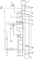
- FIG. 1 A sound system in a motor vehicle is shown in FIG. 1 using a block diagram. Loudspeakers (4), (11), (12), (13) and (14) are connected to an audio device (2) via the loudspeaker outputs (5). The lines to the individual loudspeakers are marked with (5.1) to (5.6). Crossovers (15) are provided in front of the speakers (4), (11) and (12).
- a radio (3) is also integrated in the circuit.
- the audio device (2) can be, for example, a car radio or a cassette device or a CD player and others.
- a radio telephone (3) can be understood here as a car telephone or a company radio or a speaking on-board computer or the like.
- a speaking on-board computer does not fall into the "radio" category, but in this case its assignment under the collective term "radio" is permitted.
- the driver's front loudspeaker installed in the motor vehicle is expediently used as the loudspeaker (4).
- a switch module (1) is inserted into the circuit to selectively control the loudspeaker (4) from the audio device or from the radio device.
- the speaker output (5.3) of the audio device (2) and the speaker output (6) of the radio (3) are connected to the switch module (1).
- This line (9) leads to the mute input (16) of the audio device.
- the audio device (2) and the switch module (1) are connected by the ground line (18) and the voltage supply line (17) for the switch module (1).
- a line labeled (19) leads from the switch module (1) to the common loudspeaker (4).
- the switch module (1) connects the loudspeaker output (6) of the radio to the loudspeaker (4). If the audio device (2) is now put into operation, the switch module (1) switches the speaker output (5.3) to the speaker (4), the speaker output (6) is separated from it. If the radio (3) becomes active, for example when there is an incoming call, a line switch (9) activates a mute function, which is not to be dealt with here, because it is known, in the audio device. All speakers connected to the audio device are muted. The speaker output (6) of the radio (3) is switched to the speaker (4) by the switch module (1), the speaker output (5.3) of the audio device (2) is separated from it.
- the hands-free system is now ready for operation, the user can, for example, make calls without having to carry out any manual activity.
- Said mute input (16) is present in the audio device of the exemplary embodiment listed.
- the Setup also works with audio devices without automatic mute. In this case, however, the user must turn the volume control of the audio device to zero when there is an incoming call. However, this is usually an activity that does not require too much attention and hardly distracts the driver.
- Switching the loudspeaker (4) from the audio device (2) to the radio (3) using the switch module (1) works in exactly the same way as with an audio device with mute.
- the switch module (1) is constructed in such a way that the hands-free system functions perfectly even when there is no audio device (for example in the removed state for repair and the like).
- the switch module (1) consists essentially of an electronic circuit (7) and an electromechanical switch (8).
- a relay is preferably used as the electromechanical switch (8).
- the relay ensures a potential-free switching process, safe electrical isolation, no reaction and low contact resistance.
- the position of the switching fingers (21) in the relay is such that the radio device (3) with the loudspeaker ( 4) is connected (normally closed contacts).
- the electronic circuit (7) in the switching module (1) is constructed in such a way that its function is not impaired by high-frequency interference signals.
- the resistors (20) have the function that, in the case of capacitive loudspeaker outputs from audio or radio devices, the capacitors are not charged when switching over must take place, which would result in a crack. Instead, the capacitors are constantly kept in their normal state in the charge, so there is no change in potential and therefore no cracking.
Abstract
Description
Die Erfindung bezieht sich auf eine Einrichtung zum Umschalten eines Lautsprechers nach dem Oberbegriff des Anspruchs 1. Insbesondere betrifft die Erfindung die Umschaltung eines in einem Kraftfahrzeug installierten Lautsprechers vom Lautsprecherausgang eines Audiogerätes zum Lautsprecherausgang eines Funkgerätes. Unter einem Audiogerät versteht man in diesem Fall ein Autoradio oder ein Kassettengerät oder ein CD-Abspielgerät und weitere Geräte, sowie Kombinationen derselben. Unter einem Funkgerät wiederum versteht man hier ein Autotelefongerät, ein Betriebsfunkgerät, einen sprechenden Bordcomputer oder dergleichen.The invention relates to a device for switching a loudspeaker according to the preamble of claim 1. In particular, the invention relates to the switching of a loudspeaker installed in a motor vehicle from the loudspeaker output of an audio device to the loudspeaker output of a radio device. In this case, an audio device is understood to mean a car radio or a cassette device or a CD player and other devices, as well as combinations thereof. A radio in turn is understood here to mean a car telephone, a company radio, a speaking on-board computer or the like.
In ein Kraftfahrzeug eingebaute Funkgeräte sind Stand der Technik. Die Tendenz zum Einbau solcher Geräte ist steigend, sei es nun, daß man diese Geräte bereits werkseitig einbauen läßt, oder mittels eines Nachrüstsatzes nachträglich einbaut. Beim Betrieb solcher Funkgeräte, wenn sie, was fast immer der Fall ist, von dem Fahrer bedient werden sollen, tritt das Problem auf, daß der Fahrer durch die Abnahme eines Hörers von Hand am sicheren Führen seines Kraftfahrzeuges teilweise behindert wird, weil er eben dazu nur noch eine Hand zur Verfügung hat. Oft ist bei einem ankommenden Ruf auch noch ein Blickkontakt zum Hörer erforderlich, worunter die Aufmerksamkeit des Fahrers auf den Straßenverkehr leidet.Radio equipment installed in a motor vehicle is state of the art. The tendency to install such devices is increasing, be it that these devices are already installed at the factory or retrofitted using a retrofit kit. When operating such radio devices, if they are to be operated by the driver, which is almost always the case, the problem arises that the driver is partially hampered by picking up a handset to safely drive his motor vehicle because he is doing so only has one hand left. When an incoming call is received, eye contact with the listener is often required, which reduces the driver's attention to road traffic.
Zur Vermeidung dieser Nachteile und zur Erhöhung der Sicherheit, hat man inzwischen sogenannte Freisprecheinrichtungen geschaffen, bei denen ein im Kraftfahrzeug fest eingebautes Mikrofon und ein fest eingebauter Lautsprecher verwendet werden. Der Fahrer kann also beim Bedienen des Funkgerätes sich weiter auf den Straßenverkehr konzentrieren und hat beide Hände zum Lenken seines Kraftfahrzeuges frei. Beim Einbau einer solchen Freisprecheinrichtung, insbesondere beim nachträglichen Einbau mittels eines Einbausatzes, tritt das Problem der Positionierung des Lautsprechers auf. Damit die Unterbringung eines zusätzlichen Lautsprechers nicht zu schwierig wird, werden mit den Einbausätzen meist sehr kleine und vor allem flache Lautsprecher mitgeliefert. Die Folge davon ist, daß die akustische Wiedergabe mit solch kleinen Lautsprechern äußerst schlecht ist. Bei der Wahl des Einbauortes eines zusätzlichen Lautsprechers ist außerdem darauf zu achten, daß es nicht zu akustischen Rückkopplungen kommt. Dies ist dann der Fall, wenn der vom Lautsprecher kommende verstärkte Ton vom Mikrofon wieder aufgenommen und anschließend wieder verstärkt wird. Damit kommt es zum Pfeifen in unangenehmen Frequenzlagen.To avoid these disadvantages and to increase safety, so-called hands-free devices have been created in which a microphone and a permanently installed loudspeaker are used in the motor vehicle. The driver can therefore continue to concentrate on road traffic when operating the radio and has both hands free to steer his motor vehicle. When installing such a hands-free device, in particular when retrofitting using an installation kit, the problem of positioning the loudspeaker arises. So that it is not too difficult to accommodate an additional loudspeaker, the installation kits usually come with very small and, above all, flat loudspeakers. The consequence of this is that the acoustic reproduction with such small speakers is extremely poor. When choosing the installation location of an additional loudspeaker, care must also be taken to ensure that there is no acoustic feedback. This is the case when the amplified sound coming from the loudspeaker is picked up again by the microphone and then amplified again. This leads to whistling in unpleasant frequency situations.
Eine Lösung dieses Problems wird mit dem Gegenstand des Gebrauchsmusters G 9308197.9 offenbart. Dort wird eine Freisprecheinrichtung beschrieben, die an einer beliebigen Stelle im Kraftfahrzeug montiert werden kann. Beschrieben ist beispielsweise die Befestigung an der Windschutzscheibe des Kraftfahrzeugs. Die Freisprecheinrichtung beinhaltet ein Mikrofon und einen Ohrhörer. Der Ohrhörer ist abnehmbar, indem das Ohrhörerkabel von einer im Gehäuse der Einrichtung gelagerten Kabeltrommel abgewickelt wird. Nach Gebrauch des Ohrhörers wird das Kabel entweder von Hand oder motorisch von der Kabeltrommel wieder aufgewickelt. Durch das Hören über den Ohrhörer ist eine akustische Rückkopplung ausgeschlossen. Die Aufnahme und Ablage des Ohrhörers fordert jedoch vom Benutzer eine gewisse Aufmerksamkeit, die ihn vom Führen des Kraftfahrzeuges wieder ablenkt.A solution to this problem is disclosed in the subject of utility model G 9308197.9. There a hands-free device is described, the on can be mounted anywhere in the motor vehicle. For example, the attachment to the windshield of the motor vehicle is described. The speakerphone includes a microphone and an earphone. The earphone can be removed by unwinding the earphone cable from a cable drum stored in the housing of the device. After using the earphone, the cable is rewound either by hand or by motor from the cable drum. Hearing through the earphones prevents acoustic feedback. However, the inclusion and storage of the earphones demands a certain amount of attention from the user, which distracts him from driving the motor vehicle.
Eine andere Lösung einer Freisprecheinrichtung wird in dem Dokument EP-A2-0483956 vorgestellt. Dort ist ein Autoradio zusammen mit einem Funktelefon in einem Gehäuse integriert, welches in den Normausschnitt für Autoradios in einem Armaturenbrett paßt. Beide Geräte benützen außer dem gemeinsamen Gehäuse auch die NF-Elektronik gemeinsam, sowie den fest im Kraftfahrzeug eingebauten Lautsprecher. Wird vom Funktelefon ein Funksignal empfangen, so wird das Autoradio automatisch stumm geschaltet. Diese Freisprecheinrichtung ist zweifelsfrei eine elegante Lösung, erfordert aber viel Aufwand und bringt Einschränkungen mit sich. Ein solchermaßen aufgebautes Kombinationsgerät ist sehr speziell und damit auch relativ teuer. Durch die Unterbringung von zwei Geräten in einem Gehäuse müssen Abstriche an der Funktionsvielfalt des Autoradios gemacht werden. Die Unterbringung eines Kassettenlaufwerks oder eines CD-Spielers in diesem Gemeinschaftsgehäuse wird ebenfalls sehr erschwert, wenn nicht unmöglich.Another solution of a hands-free device is presented in document EP-A2-0483956. There, a car radio is integrated together with a radio telephone in a housing, which fits into the standard cutout for car radios in a dashboard. In addition to the common housing, both devices also use the NF electronics together, as well as the loudspeaker permanently installed in the motor vehicle. If the radio telephone receives a radio signal, the car radio is automatically muted. This hands-free system is undoubtedly an elegant solution, but it requires a lot of effort and has limitations. A combination device constructed in this way is very special and therefore also relatively expensive. By accommodating two devices in one housing, the functionality of the car radio has to be cut back. It is also very difficult, if not impossible, to place a cassette drive or CD player in this shared housing.
In EP-A1-0368291 wird eine weitere Freisprecheinrichtung beschrieben, die ebenfalls eine elegante Lösung darstellt. Während das Mikrofon an einem geeigneten Ort an der Frontseite des Kraftfahrzeuges angebracht ist, befindet sich der Lautsprecher am oberen Ende der Rückenlehne des Fahrers, also ganz nahe dem Ohr des Fahrers. Bezüglich Vermeidung von Rückkopplungen ist diese Lautsprecheranordnung sicher günstig. Zur Realisierung muß jedoch eine aufwendige Verdrahtung durchgeführt werden. Vor allem zum nachträglichen Einbau in ein Kraftfahrzeug ist diese Ausführung nicht gut geeignet.EP-A1-0368291 describes a further hands-free device which also represents an elegant solution. While the microphone is attached to a suitable location on the front of the motor vehicle, the Loudspeakers at the top of the driver's backrest, i.e. very close to the driver's ear. With regard to avoiding feedback, this loudspeaker arrangement is certainly cheap. To implement this, however, complex wiring must be carried out. This version is not particularly suitable for retrofitting in a motor vehicle.
Es sind auch schon Beispiele bekannt, in denen Doppelspulen-Lautsprecher eingebaut werden, die sowohl von dem im Kraftfahrzeug eingebauten Audiogerät, als auch vom Funkgerät angesteuert werden. Solche Doppelspulen-Lautsprecher werden beispielsweise anstelle eines bereits vorhandenen Lautsprechers für das Audiogerät eingebaut. Damit ist zwar das Raumproblem gelöst, jedoch ist die Wiedergabequalität und der Wirkungsgrad nicht besonders hoch, wenn auf der einen Spule ein Audiosignal und auf der anderen Spule ein Funkgeräte-Signal wiedergegeben wird. Außerdem ist der Einbau eines Doppelspulen-Lautsprechers kostspieliger als der bereits vorhandene Einspulen-Lautsprecher.Examples are also already known in which double-coil loudspeakers are installed, which are controlled both by the audio device installed in the motor vehicle and by the radio device. Such double-coil speakers are installed, for example, instead of an existing speaker for the audio device. This solves the spatial problem, but the reproduction quality and the efficiency are not particularly high if an audio signal is reproduced on one coil and a radio signal is reproduced on the other coil. In addition, installing a double-coil speaker is more expensive than the existing single-coil speaker.
Aus der DE 33 16 818 A1 ist eine Sonnenblende mit audiovisuellen Einrichtungen bekannt. Dort lassen sich über externe Anschlußbuchsen externe Geräte wie zum Beispiel ein Autoradio, ein Bordcomputer und ähnliches anschließen, die dann einen Lautsprecher gemeinsam benutzen.
Allerdings ist hierbei nur ein externer Anschluß der Geräte möglich. Außerdem wird eine Lösung der Aufgabe der gemeinsamen Benutzung des Lautsprechers durch mehrere NF-Signalquellen nicht dargestellt.From DE 33 16 818 A1 a sun visor with audiovisual devices is known. There external devices such as a car radio, an on-board computer and the like can be connected via external connection sockets, which then share a loudspeaker.
However, only an external connection of the devices is possible. In addition, a solution to the task of sharing the loudspeaker by several LF signal sources is not shown.
Aufgabe der Erfindung ist es, eine Freisprecheinrichtung für ein Kraftfahrzeug zu schaffen, die mit möglichst geringem Material- und Arbeitsaufwand, ohne manuelle Tätigkeit des Kraftfahrzeug-Fahrers, eine einwandfreie Wiedergabe des Ausgangssignals eines Funkgerätes gewährleistet. Ein ebenfalls sich im Kraftfahrzeug befindliches Audiogerät darf.dabei die Wiedergabe des Funkgerätes nicht stören. Die Einrichtung sollte insbesondere auch für den nachträglichen Einbau in ein Kraftfahrzeug geeignet sein.The object of the invention is to provide a hands-free device for a motor vehicle, which ensures the correct reproduction of the output signal of a radio with the least possible material and labor, without manual activity by the motor vehicle driver. One is also in the motor vehicle The audio device in use must not interfere with the playback of the radio. The device should in particular also be suitable for retrofitting in a motor vehicle.
Diese Aufgabe wird durch die Merkmale des Anspruchs 1 gelöst. Die Unteransprüche zeigen zweckmäßige Ausgestaltungen der Erfindung auf.This object is solved by the features of claim 1. The subclaims show expedient embodiments of the invention.
Die Erfindung soll nun anhand der Zeichnungen näher erläutert werden. Es zeigen:
- Fig. 1 ein Blockschaltbild mit integrierter erfinderischer Einrichtung,
- Fig. 2 den Aufbau des Umschaltbausteins (1) aus der Fig. 1.
- 1 is a block diagram with an integrated inventive device,
- FIG. 2 shows the structure of the switch module (1) from FIG. 1.
In Fig. 1 ist anhand eines Blockschaltbildes eine Beschallungsanlage in einem Kraftfahrzeug dargestellt. An einem Audiogerät (2) sind Lautsprecher (4), (11), (12), (13) und (14) über die Lautsprecherausgänge (5) angeschlossen. Die Leitungen zu den einzelnen Lautsprechern sind mit (5.1) bis (5.6) gekennzeichnet. Vor den Lautsprechern (4), (11) und (12) sind Frequenzweichen (15) vorhanden. Des weiteren ist ein Funkgerät (3) in die Schaltung integriert. Bei dem Audiogerät (2) kann es sich beispielsweise um ein Autoradio oder ein Kassettengerät oder ein CD-Abspielgerät und anderes mehr handeln. Als Funkgerät (3) kann hier ein Autotelefon oder ein Betriebsfunkgerät oder ein sprechender Bordcomputer oder dergleichen verstanden werden. Genau gesehen fällt ein sprechender Bordcomputer nicht in die Kategorie "Funkgerät", jedoch sei in diesem Fall seine Zuordnung unter dem Sammelbegriff "Funkgerät" gestattet. Zur Lösung der gestellten Aufgabe soll sowohl für die Wiedergabe des Audiogerätes (2) als auch für die Wiedergabe des Funkgerätes (3) der Lautsprecher (4) verwendet werden. Als Lautsprecher (4) wird zweckmäßig der im Kraftfahrzeug eingebaute fahrerseitige Frontlautsprecher verwendet. Es kann selbstverständlich auch jeder andere der vorhandenen Lautsprecher verwendet werden. Zur wahlweisen Ansteuerung des Lautsprechers (4) vom Audiogerät oder vom Funkgerät ist in die Schaltung ein Umschaltbaustein (1) eingefügt. An dem Umschaltbaustein (1) sind der Lautsprecher-Ausgang (5.3) des Audiogerätes (2) und der Lautsprecherausgang (6) des Funkgerätes (3) angeschlossen. Ebenfalls ist ein Anschluß (10) für die Stummschaltleitung (9) des Funkgerätes (3) vorhanden. Diese Leitung (9) führt weiter zum Stummschalteingang (16) des Audiogerätes. Das Audiogerät (2) und der Umschaltbaustein (1) sind durch die Masseleitung (18) und die Spannungsversorgungsleitung (17) für den Umschaltbaustein (1) verbunden. Eine mit (19) bezeichnete Leitung führt vom Umschaltbaustein (1) zum gemeinsamen Lautsprecher (4).A sound system in a motor vehicle is shown in FIG. 1 using a block diagram. Loudspeakers (4), (11), (12), (13) and (14) are connected to an audio device (2) via the loudspeaker outputs (5). The lines to the individual loudspeakers are marked with (5.1) to (5.6). Crossovers (15) are provided in front of the speakers (4), (11) and (12). A radio (3) is also integrated in the circuit. The audio device (2) can be, for example, a car radio or a cassette device or a CD player and others. A radio telephone (3) can be understood here as a car telephone or a company radio or a speaking on-board computer or the like. Strictly speaking, a speaking on-board computer does not fall into the "radio" category, but in this case its assignment under the collective term "radio" is permitted. To solve the task set for both the playback of the audio device (2) and for Playback of the radio (3) of the speakers (4) can be used. The driver's front loudspeaker installed in the motor vehicle is expediently used as the loudspeaker (4). Of course, any other speaker can be used. A switch module (1) is inserted into the circuit to selectively control the loudspeaker (4) from the audio device or from the radio device. The speaker output (5.3) of the audio device (2) and the speaker output (6) of the radio (3) are connected to the switch module (1). There is also a connection (10) for the mute line (9) of the radio (3). This line (9) leads to the mute input (16) of the audio device. The audio device (2) and the switch module (1) are connected by the ground line (18) and the voltage supply line (17) for the switch module (1). A line labeled (19) leads from the switch module (1) to the common loudspeaker (4).
Die erfindungsgemäße Einrichtung funktioniert nun folgendermaßen:
Im Ruhezustand der Anlage verbindet der Umschaltbaustein (1) den Lautsprecherausgang (6) des Funkgerätes mit dem Lautsprecher (4). Wird nun das Audiogerät (2) in Betrieb genommen, schaltet der Umschaltbaustein (1) den Lautsprecherausgang (5.3) an den Lautsprecher (4), der Lautsprecherausgang (6) wird von diesem getrennt. Wird das Funkgerät (3), beispielsweise bei einem ankommenden Anruf, aktiv, wird über die Leitung (9) eine, hier nicht näher zu behandelnde, weil bekannte Stummschaltung, im Audiogerät aktiviert. Sämtliche am Audiogerät angeschlossenen Lautsprecher werden stumm geschaltet. Von dem Umschaltbaustein (1) wird der Lautsprecherausgang (6) des Funkgerätes (3) an den Lautsprecher (4) geschaltet, der Lautsprecherausgang (5.3) des Audiogerätes (2) wird von diesem getrennt. Jetzt ist die Freisprecheinrichtung betriebsbereit, der Benutzer kann, ohne eine manuelle Tätigkeit durchführen zu müssen, beispielsweise telefonieren. Der genannte Stummschalteingang (16) ist bei dem Audiogerät des aufgeführten Ausführungsbeispiels vorhanden. Die Einrichtung funktioniert jedoch selbstverständlich auch mit Audiogeräten ohne automatische Stummschaltung. In diesem Fall muß allerdings der Benutzer den Lautstärkeregler des Audiogerätes bei einem ankommenden Anruf auf Null drehen. Das ist aber normalerweise eine Tätigkeit, die keine allzu große Aufmerksamkeit erfordert und den Fahrer kaum ablenkt. Das Umschalten des Lautsprechers (4) vom Audiogerät (2) zum Funkgerät (3) durch den Umschaltbaustein (1) funktioniert genauso wie bei einem Audiogerät mit Stummschaltung. Der Umschaltbaustein (1) ist so aufgebaut, daß selbst beim Nichtvorhandensein eines Audiogerätes (beispielsweise im ausgebauten Zustand zur Reparatur und dergleichen) die Freisprecheinrichtung einwandfrei funktioniert.The device according to the invention now works as follows:
In the idle state of the system, the switch module (1) connects the loudspeaker output (6) of the radio to the loudspeaker (4). If the audio device (2) is now put into operation, the switch module (1) switches the speaker output (5.3) to the speaker (4), the speaker output (6) is separated from it. If the radio (3) becomes active, for example when there is an incoming call, a line switch (9) activates a mute function, which is not to be dealt with here, because it is known, in the audio device. All speakers connected to the audio device are muted. The speaker output (6) of the radio (3) is switched to the speaker (4) by the switch module (1), the speaker output (5.3) of the audio device (2) is separated from it. The hands-free system is now ready for operation, the user can, for example, make calls without having to carry out any manual activity. Said mute input (16) is present in the audio device of the exemplary embodiment listed. The Setup, of course, also works with audio devices without automatic mute. In this case, however, the user must turn the volume control of the audio device to zero when there is an incoming call. However, this is usually an activity that does not require too much attention and hardly distracts the driver. Switching the loudspeaker (4) from the audio device (2) to the radio (3) using the switch module (1) works in exactly the same way as with an audio device with mute. The switch module (1) is constructed in such a way that the hands-free system functions perfectly even when there is no audio device (for example in the removed state for repair and the like).
In der Fig. 2 sind nun Einzelheiten über den Aufbau des Umschaltbausteins (1) aufgezeigt. Der Umschaltbaustein (1) besteht im wesentlichen aus einer elektronischen Schaltung (7) und einem elektromechanischen Umschalter (8). Als elektromechanischer Umschalter (8) wird vorzugsweise ein Relais verwendet. Das Relais gewährleistet einen potentialfreien Schaltvorgang, eine sichere galvanische Trennung, keine Rückwirkung und geringe Übergangswiderstände. Im Ruhezustand des Relais, d.h. wenn an den beiden Eingängen (17) und (18) keine Spannung vom Audiogerät (2) anliegt, ist die Stellung der Schaltfinger (21) im Relais so, daß immer das Funkgerät (3) mit dem Lautsprecher (4) verbunden ist (Ruhekontakte). Erst beim Anliegen einer Schaltspannung an den Eingängen (17) und (18) wird die Relaisspule (19) von einem Strom durchflossen, der Magnet des Relais zieht und die Schaltfinger (21) verbinden den Lautsprecher (4) mit dem Lautsprecherausgang (5.3) des Audiogerätes. Durch die Ruhestellung der Schaltfinger (21) bei inaktivem, d.h. eventuell auch ausgebautem Audiogerät (2), ist die Funktionsbereitschaft der Freisprecheinrichtung immer gewährleistet. Die elektronische Schaltung (7) im Umschaltbaustein (1) ist so aufgebaut, daß sie durch hochfrequente Störsignale nicht in ihrer Funktion beeinträchtigt wird. Die Widerstände (20) haben die Funktion, daß bei kapazitiven Lautsprecherausgängen von Audio- bzw. Funkgeräten keine Aufladung der Kondensatoren beim Umschalten erfolgen muß, wodurch ein Knacken entstehen würde. Stattdessen werden die Kondensatoren ständig entsprechend in der Ladung auf ihrem Normalzustand gehalten, es erfolgt.somit keine Potentialänderung und damit kein Knacken.2 now shows details of the structure of the switch module (1). The switch module (1) consists essentially of an electronic circuit (7) and an electromechanical switch (8). A relay is preferably used as the electromechanical switch (8). The relay ensures a potential-free switching process, safe electrical isolation, no reaction and low contact resistance. In the idle state of the relay, i.e. if there is no voltage from the audio device (2) at the two inputs (17) and (18), the position of the switching fingers (21) in the relay is such that the radio device (3) with the loudspeaker ( 4) is connected (normally closed contacts). Only when a switching voltage is applied to the inputs (17) and (18) is the relay coil (19) flowed through by a current, the magnet of the relay pulls and the switching fingers (21) connect the loudspeaker (4) to the loudspeaker output (5.3) of the Audio device. The operational readiness of the hands-free device is always guaranteed by the rest position of the shift fingers (21) when the audio device (2) is inactive, ie possibly also removed. The electronic circuit (7) in the switching module (1) is constructed in such a way that its function is not impaired by high-frequency interference signals. The resistors (20) have the function that, in the case of capacitive loudspeaker outputs from audio or radio devices, the capacitors are not charged when switching over must take place, which would result in a crack. Instead, the capacitors are constantly kept in their normal state in the charge, so there is no change in potential and therefore no cracking.
Claims (6)
dadurch gekennzeichnet,
daß ein Umschaltbaustein (1) vorhanden ist, der bei einem vorhandenen Einoder Ausgangssignal am Funkgerät (3) den Lautsprecher (4) an den Lautsprecherausgang (6) des Funkgerätes (3) schaltet und ihn gleichzeitig vom Lautsprecherausgang (5) des Audiogerätes (2) trennt, und daß zwischen den Lautsprecherausgängen (5.3, 6) von Audiogerät (2) bzw. Funkgerät (3) und dem Umschaltbaustein (1) jeweils ein Widerstand (20) derart angeordnet ist, daß beim Umschaltvorgang keine Knackstörungen auftreten.Device for switching a loudspeaker (4) in a motor vehicle interior between an audio device (2) and a radio (3), the loudspeaker outputs (5) of the audio device (2) being electronically muted when an input or output signal on the radio (3) is present
characterized,
that a switching module (1) is present, which switches the loudspeaker (4) to the loudspeaker output (6) of the radio (3) when there is an input or output signal on the radio (3) and simultaneously switches it from the loudspeaker output (5) of the audio device (2) separates, and that between the loudspeaker outputs (5.3, 6) of the audio device (2) or radio (3) and the switching module (1) a resistor (20) is arranged in such a way that no clicks occur during the switching process.
dadurch gekennzeichnet,
daß der Umschaltbaustein (1) aus einer elektronischen Schaltung (7) und einem elektromechanischen Umschalter (8) besteht.Device according to claim 1,
characterized,
that the switch module (1) consists of an electronic circuit (7) and an electromechanical switch (8).
dadurch gekennzeichnet,
daß der elektromechanische Umschalter (8) ein Relais istDevice according to claims 1 and 2,
characterized,
that the electromechanical switch (8) is a relay
dadurch gekennzeichnet,
daß der elektromechanische Umschalter (8) immer die Verbindung zwischen dem Lautsprecher (4) und dem Funkgerät (3) schaltet, wenn das Audiogerät (2) nicht in Betrieb ist.Device according to claims 1 to 3,
characterized,
that the electromechanical switch (8) always switches the connection between the loudspeaker (4) and the radio (3) when the audio device (2) is not in operation.
dadurch gekennzeichnet,
daß der elektromechanische Umschalter (8) den Lautsprecherausgang (5) des Audiogerätes (2) mit dem Lautsprecher (4) verbindet, wenn das Audiogerät (2) in Betrieb und das Funkgerät (3) nicht aktiv ist.Device according to one or more of claims 1 to 4,
characterized,
that the electromechanical switch (8) connects the speaker output (5) of the audio device (2) to the speaker (4) when the audio device (2) is in operation and the radio (3) is not active.
dadurch gekennzeichnet,
daß es sich bei dem Lautsprecher (4) um den frontseitigen Lautsprecher auf der Fahrerseite eines Kraftfahrzeuges handelt.Device according to claim 1,
characterized,
that the speaker (4) is the front speaker on the driver's side of a motor vehicle.
Applications Claiming Priority (2)
| Application Number | Priority Date | Filing Date | Title |
|---|---|---|---|
| DE4342917 | 1993-12-16 | ||
| DE4342917A DE4342917A1 (en) | 1993-12-16 | 1993-12-16 | Device for switching a speaker |
Publications (3)
| Publication Number | Publication Date |
|---|---|
| EP0659029A2 true EP0659029A2 (en) | 1995-06-21 |
| EP0659029A3 EP0659029A3 (en) | 1996-02-07 |
| EP0659029B1 EP0659029B1 (en) | 2000-10-18 |
Family
ID=6505174
Family Applications (1)
| Application Number | Title | Priority Date | Filing Date |
|---|---|---|---|
| EP94119808A Expired - Lifetime EP0659029B1 (en) | 1993-12-16 | 1994-12-15 | Loudspeaker selection device |
Country Status (3)
| Country | Link |
|---|---|
| EP (1) | EP0659029B1 (en) |
| AT (1) | ATE197107T1 (en) |
| DE (2) | DE4342917A1 (en) |
Cited By (3)
| Publication number | Priority date | Publication date | Assignee | Title |
|---|---|---|---|---|
| WO2000036759A1 (en) * | 1998-11-27 | 2000-06-22 | Kyrel Oy | An assembly for hands-free function of a telephone |
| EP1341394A1 (en) * | 2002-02-27 | 2003-09-03 | Thomson Licensing S.A. | Electronic audio signal processing device |
| DE202011003798U1 (en) | 2011-03-04 | 2011-05-26 | Hilse, Andreas, 10437 | Mobile home sound system with automatic source switching |
Families Citing this family (7)
| Publication number | Priority date | Publication date | Assignee | Title |
|---|---|---|---|---|
| DE19614148C1 (en) * | 1996-04-10 | 1997-09-04 | Bosch Gmbh Robert | Telephone device with a connection for a telephone handset |
| DE19725284C2 (en) * | 1997-06-13 | 1999-08-05 | Mechatronik Automobilausruestu | Device and method for installing a hands-free circuit for a telephone in a motor vehicle |
| DE19742797C1 (en) * | 1997-09-27 | 1999-04-22 | Grundig Ag | Motor vehicle communication device |
| JP3042681B2 (en) * | 1998-04-15 | 2000-05-15 | 怡利電子工業股▲ひん▼有限公司 | A handset that does not need to be gripped by a mobile phone combined with the speaker of a car audio system |
| DE19942858C2 (en) * | 1999-09-08 | 2003-04-03 | Am3 Automotive Multimedia Ag | Seat-related sound system |
| DE19945620A1 (en) * | 1999-09-23 | 2001-04-12 | Siemens Ag | Attachment device for mobile telephone has holder with accommodation device for connector, device for fixing holder in vehicle, device with data line for transferring antenna signals |
| US7096047B2 (en) | 2001-11-30 | 2006-08-22 | Motorola, Inc. | Electronic audio accessory for use with automotive stereo loudspeakers |
Citations (3)
| Publication number | Priority date | Publication date | Assignee | Title |
|---|---|---|---|---|
| DE3316818A1 (en) | 1983-05-07 | 1984-11-08 | Hans-Hellmut Dipl.-Ing. 2061 Sülfeld Ernst | SUN VISOR WITH AUDIOVISUAL FACILITIES |
| EP0368291A1 (en) | 1988-11-09 | 1990-05-16 | Nokia Mobile Phones Ltd. | An arrangement in two-way telephone communication |
| EP0483956A2 (en) | 1990-10-30 | 1992-05-06 | Nokia Mobile Phones (U.K.) Limited | Combined broadcast radio receiver and radio telephone |
Family Cites Families (6)
| Publication number | Priority date | Publication date | Assignee | Title |
|---|---|---|---|---|
| JPS52127713U (en) * | 1976-03-26 | 1977-09-28 | ||
| US4060766A (en) * | 1976-05-07 | 1977-11-29 | Nissan Denshi Company Limited | Automatic signal switching apparatus for a combined transceiver and radio or tape recorder set |
| WO1987000718A1 (en) * | 1985-07-19 | 1987-01-29 | Custom Product Development Pty. Ltd. | Mobile telephone system |
| DE3903461A1 (en) * | 1989-02-06 | 1990-08-09 | Grundig Emv | COMBINATION OF A CAR RADIO WITH OTHER COMMUNICATION MEANS |
| AU5095190A (en) * | 1989-02-14 | 1990-09-05 | In-Car Systems Limited | Vehicle telephone apparatus |
| DE9308197U1 (en) * | 1993-06-01 | 1993-07-29 | E. Lead Electronic Co. Ltd., Changhua, Tw |
-
1993
- 1993-12-16 DE DE4342917A patent/DE4342917A1/en not_active Ceased
-
1994
- 1994-12-15 AT AT94119808T patent/ATE197107T1/en not_active IP Right Cessation
- 1994-12-15 EP EP94119808A patent/EP0659029B1/en not_active Expired - Lifetime
- 1994-12-15 DE DE59409552T patent/DE59409552D1/en not_active Expired - Lifetime
Patent Citations (3)
| Publication number | Priority date | Publication date | Assignee | Title |
|---|---|---|---|---|
| DE3316818A1 (en) | 1983-05-07 | 1984-11-08 | Hans-Hellmut Dipl.-Ing. 2061 Sülfeld Ernst | SUN VISOR WITH AUDIOVISUAL FACILITIES |
| EP0368291A1 (en) | 1988-11-09 | 1990-05-16 | Nokia Mobile Phones Ltd. | An arrangement in two-way telephone communication |
| EP0483956A2 (en) | 1990-10-30 | 1992-05-06 | Nokia Mobile Phones (U.K.) Limited | Combined broadcast radio receiver and radio telephone |
Cited By (3)
| Publication number | Priority date | Publication date | Assignee | Title |
|---|---|---|---|---|
| WO2000036759A1 (en) * | 1998-11-27 | 2000-06-22 | Kyrel Oy | An assembly for hands-free function of a telephone |
| EP1341394A1 (en) * | 2002-02-27 | 2003-09-03 | Thomson Licensing S.A. | Electronic audio signal processing device |
| DE202011003798U1 (en) | 2011-03-04 | 2011-05-26 | Hilse, Andreas, 10437 | Mobile home sound system with automatic source switching |
Also Published As
| Publication number | Publication date |
|---|---|
| DE4342917A1 (en) | 1995-06-22 |
| DE59409552D1 (en) | 2000-11-23 |
| EP0659029B1 (en) | 2000-10-18 |
| ATE197107T1 (en) | 2000-11-15 |
| EP0659029A3 (en) | 1996-02-07 |
Similar Documents
| Publication | Publication Date | Title |
|---|---|---|
| DE19830247C2 (en) | Integrated hands-free mobile phone system combined with vehicle stereo speakers | |
| EP0659029B1 (en) | Loudspeaker selection device | |
| DE102005029690A1 (en) | Car telephone system | |
| EP0898814B1 (en) | Broadcast receiver with integrated telephone unit | |
| EP0809413A1 (en) | Audio devide for a vehicle | |
| DE10392880T5 (en) | Noise reduction system and headphones for this | |
| EP1018288A1 (en) | Car radio system | |
| DE2840713B2 (en) | System for the transmission of speech and music to a plurality of seats, in particular seats of a vehicle | |
| DE60104534T2 (en) | Hands-free unit for vehicles | |
| EP0966100B1 (en) | Method and means for influencing the volume of audio reproducing devices in motor vehicles | |
| EP2323424A1 (en) | Audio system for a vehicle | |
| DE10032666B4 (en) | Audio system for a motor vehicle | |
| DE10057261C2 (en) | Audio system for a motor vehicle | |
| EP1004170B1 (en) | Device for playing back audio signals in a motor vehicle | |
| DE60111300T2 (en) | Communication system, selection means for a communication system and use thereof | |
| DE4233721A1 (en) | Communication device for use in police motorcycles | |
| DE19742797C1 (en) | Motor vehicle communication device | |
| EP0560446A2 (en) | Telecommunication apparatus with a hands-free telephone device | |
| EP3388387B1 (en) | Integration of multimedia components into the vehicle network of industrial trucks | |
| DE10126673B4 (en) | Motor vehicle with information system | |
| DE19725284C2 (en) | Device and method for installing a hands-free circuit for a telephone in a motor vehicle | |
| EP0509195B1 (en) | Acoustic irradiation installation of an automobile | |
| DE19954824A1 (en) | Audio system for vehicle, has audio data source, amplifier for processing audio data into audio signals for loudspeaker units, and subwoofer unit connected to audio data source or amplifier | |
| DE3138846A1 (en) | Communication system for road users with helmets | |
| DE10257677B4 (en) | Audio system with automatic mute |
Legal Events
| Date | Code | Title | Description |
|---|---|---|---|
| PUAI | Public reference made under article 153(3) epc to a published international application that has entered the european phase |
Free format text: ORIGINAL CODE: 0009012 |
|
| AK | Designated contracting states |
Kind code of ref document: A2 Designated state(s): AT DE FR GB IT |
|
| RAP1 | Party data changed (applicant data changed or rights of an application transferred) |
Owner name: GRUNDIG E.M.V. ELEKTRO-MECHANISCHE VERSUCHSANSTALT |
|
| PUAL | Search report despatched |
Free format text: ORIGINAL CODE: 0009013 |
|
| AK | Designated contracting states |
Kind code of ref document: A3 Designated state(s): AT DE FR GB IT |
|
| 17P | Request for examination filed |
Effective date: 19960228 |
|
| RAP1 | Party data changed (applicant data changed or rights of an application transferred) |
Owner name: GRUNDIG AKTIENGESELLSCHAFT |
|
| GRAG | Despatch of communication of intention to grant |
Free format text: ORIGINAL CODE: EPIDOS AGRA |
|
| 17Q | First examination report despatched |
Effective date: 19991005 |
|
| GRAG | Despatch of communication of intention to grant |
Free format text: ORIGINAL CODE: EPIDOS AGRA |
|
| GRAH | Despatch of communication of intention to grant a patent |
Free format text: ORIGINAL CODE: EPIDOS IGRA |
|
| GRAH | Despatch of communication of intention to grant a patent |
Free format text: ORIGINAL CODE: EPIDOS IGRA |
|
| GRAA | (expected) grant |
Free format text: ORIGINAL CODE: 0009210 |
|
| AK | Designated contracting states |
Kind code of ref document: B1 Designated state(s): AT DE FR GB IT |
|
| REF | Corresponds to: |
Ref document number: 197107 Country of ref document: AT Date of ref document: 20001115 Kind code of ref document: T |
|
| GBT | Gb: translation of ep patent filed (gb section 77(6)(a)/1977) |
Effective date: 20001018 |
|
| REF | Corresponds to: |
Ref document number: 59409552 Country of ref document: DE Date of ref document: 20001123 |
|
| RAP2 | Party data changed (patent owner data changed or rights of a patent transferred) |
Owner name: GRUNDIG AKTIENGESELLSCHAFT |
|
| PG25 | Lapsed in a contracting state [announced via postgrant information from national office to epo] |
Ref country code: AT Free format text: LAPSE BECAUSE OF NON-PAYMENT OF DUE FEES Effective date: 20001215 |
|
| REG | Reference to a national code |
Ref country code: GB Ref legal event code: 746 Effective date: 20001130 |
|
| ET | Fr: translation filed | ||
| ITF | It: translation for a ep patent filed |
Owner name: STUDIO JAUMANN P. & C. S.N.C. |
|
| PLBE | No opposition filed within time limit |
Free format text: ORIGINAL CODE: 0009261 |
|
| STAA | Information on the status of an ep patent application or granted ep patent |
Free format text: STATUS: NO OPPOSITION FILED WITHIN TIME LIMIT |
|
| 26N | No opposition filed | ||
| REG | Reference to a national code |
Ref country code: GB Ref legal event code: IF02 |
|
| REG | Reference to a national code |
Ref country code: FR Ref legal event code: TP |
|
| REG | Reference to a national code |
Ref country code: GB Ref legal event code: 732E |
|
| PGFP | Annual fee paid to national office [announced via postgrant information from national office to epo] |
Ref country code: GB Payment date: 20041206 Year of fee payment: 11 |
|
| PG25 | Lapsed in a contracting state [announced via postgrant information from national office to epo] |
Ref country code: IT Free format text: LAPSE BECAUSE OF NON-PAYMENT OF DUE FEES;WARNING: LAPSES OF ITALIAN PATENTS WITH EFFECTIVE DATE BEFORE 2007 MAY HAVE OCCURRED AT ANY TIME BEFORE 2007. THE CORRECT EFFECTIVE DATE MAY BE DIFFERENT FROM THE ONE RECORDED. Effective date: 20051215 Ref country code: GB Free format text: LAPSE BECAUSE OF NON-PAYMENT OF DUE FEES Effective date: 20051215 |
|
| GBPC | Gb: european patent ceased through non-payment of renewal fee |
Effective date: 20051215 |
|
| REG | Reference to a national code |
Ref country code: FR Ref legal event code: TP |
|
| PGFP | Annual fee paid to national office [announced via postgrant information from national office to epo] |
Ref country code: DE Payment date: 20131230 Year of fee payment: 20 |
|
| PGFP | Annual fee paid to national office [announced via postgrant information from national office to epo] |
Ref country code: FR Payment date: 20131217 Year of fee payment: 20 |
|
| REG | Reference to a national code |
Ref country code: DE Ref legal event code: R071 Ref document number: 59409552 Country of ref document: DE |