EP0658922A2 - Illumination unit; and electrodeless low-pressure discharge lamp, holder, and supply unit suitable for use in the illumination unit - Google Patents
Illumination unit; and electrodeless low-pressure discharge lamp, holder, and supply unit suitable for use in the illumination unit Download PDFInfo
- Publication number
- EP0658922A2 EP0658922A2 EP94203582A EP94203582A EP0658922A2 EP 0658922 A2 EP0658922 A2 EP 0658922A2 EP 94203582 A EP94203582 A EP 94203582A EP 94203582 A EP94203582 A EP 94203582A EP 0658922 A2 EP0658922 A2 EP 0658922A2
- Authority
- EP
- European Patent Office
- Prior art keywords
- illumination unit
- voltage
- lamp
- ignition
- supply
- Prior art date
- Legal status (The legal status is an assumption and is not a legal conclusion. Google has not performed a legal analysis and makes no representation as to the accuracy of the status listed.)
- Granted
Links
Images
Classifications
-
- H—ELECTRICITY
- H05—ELECTRIC TECHNIQUES NOT OTHERWISE PROVIDED FOR
- H05B—ELECTRIC HEATING; ELECTRIC LIGHT SOURCES NOT OTHERWISE PROVIDED FOR; CIRCUIT ARRANGEMENTS FOR ELECTRIC LIGHT SOURCES, IN GENERAL
- H05B41/00—Circuit arrangements or apparatus for igniting or operating discharge lamps
- H05B41/14—Circuit arrangements
- H05B41/26—Circuit arrangements in which the lamp is fed by power derived from dc by means of a converter, e.g. by high-voltage dc
- H05B41/28—Circuit arrangements in which the lamp is fed by power derived from dc by means of a converter, e.g. by high-voltage dc using static converters
- H05B41/2806—Circuit arrangements in which the lamp is fed by power derived from dc by means of a converter, e.g. by high-voltage dc using static converters with semiconductor devices and specially adapted for lamps without electrodes in the vessel, e.g. surface discharge lamps, electrodeless discharge lamps
- H05B41/2813—Arrangements for protecting lamps or circuits against abnormal operating conditions
-
- H—ELECTRICITY
- H01—ELECTRIC ELEMENTS
- H01J—ELECTRIC DISCHARGE TUBES OR DISCHARGE LAMPS
- H01J61/00—Gas-discharge or vapour-discharge lamps
- H01J61/02—Details
- H01J61/54—Igniting arrangements, e.g. promoting ionisation for starting
- H01J61/541—Igniting arrangements, e.g. promoting ionisation for starting using a bimetal switch
- H01J61/544—Igniting arrangements, e.g. promoting ionisation for starting using a bimetal switch and an auxiliary electrode outside the vessel
-
- H—ELECTRICITY
- H01—ELECTRIC ELEMENTS
- H01J—ELECTRIC DISCHARGE TUBES OR DISCHARGE LAMPS
- H01J61/00—Gas-discharge or vapour-discharge lamps
- H01J61/02—Details
- H01J61/56—One or more circuit elements structurally associated with the lamp
-
- H—ELECTRICITY
- H01—ELECTRIC ELEMENTS
- H01J—ELECTRIC DISCHARGE TUBES OR DISCHARGE LAMPS
- H01J65/00—Lamps without any electrode inside the vessel; Lamps with at least one main electrode outside the vessel
- H01J65/04—Lamps in which a gas filling is excited to luminesce by an external electromagnetic field or by external corpuscular radiation, e.g. for indicating plasma display panels
- H01J65/042—Lamps in which a gas filling is excited to luminesce by an external electromagnetic field or by external corpuscular radiation, e.g. for indicating plasma display panels by an external electromagnetic field
- H01J65/048—Lamps in which a gas filling is excited to luminesce by an external electromagnetic field or by external corpuscular radiation, e.g. for indicating plasma display panels by an external electromagnetic field the field being produced by using an excitation coil
-
- H—ELECTRICITY
- H05—ELECTRIC TECHNIQUES NOT OTHERWISE PROVIDED FOR
- H05B—ELECTRIC HEATING; ELECTRIC LIGHT SOURCES NOT OTHERWISE PROVIDED FOR; CIRCUIT ARRANGEMENTS FOR ELECTRIC LIGHT SOURCES, IN GENERAL
- H05B41/00—Circuit arrangements or apparatus for igniting or operating discharge lamps
- H05B41/14—Circuit arrangements
- H05B41/24—Circuit arrangements in which the lamp is fed by high frequency ac, or with separate oscillator frequency
-
- H—ELECTRICITY
- H05—ELECTRIC TECHNIQUES NOT OTHERWISE PROVIDED FOR
- H05B—ELECTRIC HEATING; ELECTRIC LIGHT SOURCES NOT OTHERWISE PROVIDED FOR; CIRCUIT ARRANGEMENTS FOR ELECTRIC LIGHT SOURCES, IN GENERAL
- H05B41/00—Circuit arrangements or apparatus for igniting or operating discharge lamps
- H05B41/14—Circuit arrangements
- H05B41/26—Circuit arrangements in which the lamp is fed by power derived from dc by means of a converter, e.g. by high-voltage dc
- H05B41/28—Circuit arrangements in which the lamp is fed by power derived from dc by means of a converter, e.g. by high-voltage dc using static converters
- H05B41/2806—Circuit arrangements in which the lamp is fed by power derived from dc by means of a converter, e.g. by high-voltage dc using static converters with semiconductor devices and specially adapted for lamps without electrodes in the vessel, e.g. surface discharge lamps, electrodeless discharge lamps
-
- Y—GENERAL TAGGING OF NEW TECHNOLOGICAL DEVELOPMENTS; GENERAL TAGGING OF CROSS-SECTIONAL TECHNOLOGIES SPANNING OVER SEVERAL SECTIONS OF THE IPC; TECHNICAL SUBJECTS COVERED BY FORMER USPC CROSS-REFERENCE ART COLLECTIONS [XRACs] AND DIGESTS
- Y02—TECHNOLOGIES OR APPLICATIONS FOR MITIGATION OR ADAPTATION AGAINST CLIMATE CHANGE
- Y02B—CLIMATE CHANGE MITIGATION TECHNOLOGIES RELATED TO BUILDINGS, e.g. HOUSING, HOUSE APPLIANCES OR RELATED END-USER APPLICATIONS
- Y02B20/00—Energy efficient lighting technologies, e.g. halogen lamps or gas discharge lamps
Definitions
- the invention relates to an illumination unit comprising an electrodeless low-pressure discharge lamp, which illumination unit is provided with a lamp vessel enclosing a discharge space which contains an ionizable filling, a holder for the lamp vessel, a coil for generating a high-frequency magnetic field for maintaining an electric discharge in the discharge space, a high-frequency supply for the coil, and ignition aids for promoting an initiation of the discharge, which coil is provided with a primary and a secondary winding, the primary winding having a first and a second end which are connected to a first and a second contact, respectively, of the supply, while in a nominal operational state of the illumination unit the first contact supplies a high-frequency voltage and the second contact supplies a reference voltage free from high-frequency variations, in which state a voltage gradient arises in the primary winding in a direction from the first to the second end, and in the secondary winding a voltage gradient is generated in a direction from a first to a second end which is opposed to that from the first to the second end in the
- the invention also relates to an electrodeless low-pressure discharge lamp suitable for use in the illumination unit, and also to a holder and to a supply unit suitable for use in such an illumination unit.
- Such an illumination unit is known from EP 0.332.263 A1.
- the supply is accommodated in a housing fastened to the lamp vessel.
- a first contact of the supply delivers a voltage which varies with high frequency, i.e. with a frequency above 20 kHz. In fact, the frequency is approximately 3 MHz.
- the supply has a second contact which supplies a reference voltage free from high-frequency variations.
- the reference voltage is, for example, equal to earth potential, but may alternatively be any other voltage free from high-frequency variations.
- This asymmetrical supply may be comparatively simple in comparison with a symmetrical supply, i.e. a supply in which the voltages at the contacts are in mutually opposed faces.
- the lamp vessel has a luminescent layer at its inside and is provided with a filling containing mercury.
- the coil has a primary winding of 13 turns and a secondary winding of 14.5 turns.
- the turns in this known illumination unit all have the same winding direction and extend over a length of 30 mm around a core of soft-magnetic material with a length of 50 mm.
- the secondary winding has a first free end. An opposed, second end is connected to the second contact of the supply. During operation, a voltage is generated in the secondary winding which has a gradient from the reference voltage at the second end to a voltage at the first end which has approximately the same value, but with opposite sign, as that of the first contact.
- High-frequency variations in the voltage averaged over the coil surface therefore have an amplitude which is comparatively small compared with high-frequency variations of the voltage averaged over the surface area of the primary winding.
- the interference caused by the illumination unit is accordingly comparatively small compared with that in the case of an illumination unit with a primary winding only.
- the voltage gradients in these windings have the same direction.
- a voltage gradient accordingly occurs in the secondary winding which is opposed to that from the first to the second end of the primary winding in a direction opposed to that from the first to the second end of the primary winding.
- the direction from the first to the second end of the primary winding accordingly is opposed to that from the first to the second end of the primary winding.
- the winding direction of the secondary winding is chosen to be opposed to that of the primary winding, the voltage gradients in these windings are of opposite directions. In that case the direction from the first to the second end of the secondary winding is equal to that from the first to the second end of the primary winding.
- the voltage gradient in the primary winding and that in the secondary winding jointly result in an electric field in the discharge space.
- This field is capable of igniting the lamp at a sufficiently high amplitude of the voltage delivered by the supply.
- the known illumination unit has an electrical conductor at the first end of each of the windings.
- the conductors carry a voltage which differs comparatively strongly from the reference voltage. Unlike the windings, the conductors are at a comparatively great distance from one another. These ignition aids accordingly prevent the electric field lines from concentrating around the windings. An electric field is thus generated in the discharge space which is strong enough for igniting the lamp already at a comparatively low voltage across the primary winding.
- the invention has for its object to provide a measure in an illumination unit of the kind mentioned in the opening paragraph which also results in a comparatively low ignition voltage of the lamp, but which renders it possible to avoid the above disadvantage.
- the illumination unit is for this purpose characterized in that, after switching-on, the ignition aids achieve that the nominal operational state is preceded by an ignition state in which the second end of the secondary winding is disconnected from the second contact of the supply unit.
- the secondary winding need not hamper lamp ignition in spite of the fact that in the ignition state a voltage gradient is generated in the secondary winding whose value corresponds to that obtaining during the nominal operational state. Since the second end of the secondary winding is disconnected from the second contact of the supply in the ignition state, the interval over which the voltage has its gradient differs from that during the nominal operational state. Contributions to the electric field resulting from high-frequency voltage differences between the windings and earth do not cancel one another out in the ignition state. The inventors have found that a considerably lower ignition voltage can suffice under these circumstances compared with the case in which the second end of the secondary winding is connected to the second contact of the supply. Since the ignition state lasts much shorter than the nominal operational state, the measure renders it possible to avoid the disadvantage mentioned above.
- the secondary winding may be permanently connected with one end to the second contact of the supply.
- the illumination unit is then brought into the ignition state in that a bipolar switch interchanges the connections of the ends of the primary winding to the supply contacts.
- This switching of the connections reverses the voltage gradient in the primary, and thus also in the secondary winding.
- the voltage interval traversed in the primary winding remains the same.
- the voltage interval traversed during the ignition state differs from that during the nominal operational state.
- the voltage is equal to the reference voltage at the permanently connected end. Since the voltage gradient is reversed, the voltage changes towards the other end to a value opposed to that which it would have during the nominal operational state.
- Electric fields caused by voltage variations in the secondary winding thus reinforce those which are derived from the primary winding, so that the lamp will ignite readily.
- the switching of the connections causes the ends to interchange their functions.
- the second end is an end which is disconnected from the second contact of the supply.
- An attractive embodiment of the illumination unit according to the invention is characterized in that the ignition aids between the second end of the secondary winding and the second contact of the supply comprise a first switch which is open in the ignition state and closed in the nominal operational state.
- the switch is, for example, a semiconductor switch.
- a favourable modification of the above embodiment is characterized in that the secondary winding is decoupled in the ignition state.
- a single switch can suffice in this way.
- the average voltage of the secondary winding cannot change because no charge can flow to or from the secondary winding in the decoupled state.
- High-frequency variations in the average voltage of the primary winding are not compensated by those in the secondary winding as a result.
- the ignition aids in addition comprise a second switch, which is closed in the ignition state and open in the nominal operational state, between the first contact of the supply and the first end of the secondary winding.
- a second switch which is closed in the ignition state and open in the nominal operational state, between the first contact of the supply and the first end of the secondary winding.
- the ignition state may have a predetermined duration, for example, because a timer switch is used which causes the illumination unit to enter the nominal operational state, for example, 100 ms after switching-on.
- the transition from the ignition state to the nominal operational state is dependent on a lamp parameter. It is achieved in a simple manner thereby that the ignition state does not end before the lamp has ignited. The beginning of the nominal operational state depends, for example, on the power consumed by the lamp.
- An attractive embodiment of the illumination unit according to the invention is characterized in that said lamp parameter is a temperature.
- This may be, for example, the temperature in a location at the surface of the lamp vessel.
- the transition from the ignition state to the nominal operational state is realised, for example, by means of one or several bimetal switches arranged in the vicinity of the lamp vessel. Such switches may be comparatively inexpensive.
- a very attractive embodiment is characterized in that said lamp parameter is light generated by the lamp.
- the nominal operational state can then commence immediately after the lamp has ignited.
- the supply unit is accommodated in a holder fastened to the lamp vessel.
- the supply unit may be accommodated in a separate housing, the electrodeless lamp being connected to the supply unit by means of a cable.
- the invention accordingly also applies to an electrodeless low-pressure discharge lamp suitable for use in an illumination unit as described with reference to one of the above embodiments of the invention, which lamp is provided with the lamp vessel, the holder, the coil, and the ignition aids.
- the lamp vessel may be detachably coupled to the holder. If so desired, it may then be replaced by a new lamp vessel, for example, one provided with a luminescent layer which luminesces at a different colour temperature.
- a holder according to the invention suitable for use in an illumination unit as described above is provided with the coil and with the ignition aids, while the lamp vessel can be coupled to the holder.
- the ignition aids for the lamp may form a supply device in conjunction with the supply unit.
- a supply device according to the invention suitable for use in an illumination unit as described above with reference to one of the embodiments is provided with the high-frequency supply and with the ignition aids.
- An embodiment of the supply device according to the invention is characterized in that the supply device is in addition provided with the coil.
- the illumination unit shown in Fig. 1 comprises an electrodeless low-pressure discharge lamp 10.
- the illumination unit is provided with a lamp vessel 20 which encloses a discharge space 21 and contains an ionizable filling.
- the lamp vessel 20 has at an inner surface 22 a luminescent layer 23 which comprises green-luminescing terbium-activated cerium-magnesium aluminate and red-luminescing yttrium oxide activated by trivalent europium.
- the illumination unit is further provided with a holder 60 for the lamp vessel, with a coil 30 for generating a high-frequency magnetic field so as to maintain an electric discharge in the discharge space 21, and with a high-frequency supply 50 for the coil 30.
- the lamp vessel 20 may be detachably coupled to the holder 60.
- the illumination unit is also provided with ignition aids 40 for promoting the initiation of the discharge.
- the coil 30 has a primary 31 and a secondary winding 32 around a core 33 of soft-magnetic material, here of Philips 4C6 ferrite (diagrammatically indicated in Fig. 2). Alternatively, a core may be absent. In the embodiment shown, the primary and the secondary winding have the same winding direction.
- the primary winding 31 has a first and a second end 34A, 34B which are connected to a first and a second contact 51, 52, respectively, of the supply 50.
- the first contact 51 of the supply 50 delivers a high-frequency voltage (V) relative to earth M.
- the second contact 52 supplies a reference voltage (N) which is free from high-frequency variations.
- the supply 50 accommodated in an earthed housing 53 furthermore has a first and a second input terminal 54, 55, for example for connection to the mains.
- a voltage gradient over the interval (V, 0) arises in a direction from the first 34A to the second end 34B in the primary winding 31.
- a voltage gradient over the interval (-V, 0) is generated in a direction from a first 35A to a second end 35B which is opposed to the voltage gradient from the first to the second end 34A, 34B in the primary winding 31.
- the absolute value of the voltage gradient in the secondary winding 32 is the same as that in the primary winding 31.
- the secondary winding 32 already provides a considerable reduction in interference if the absolute value of the voltage gradient therein is of the same order of magnitude as that in the primary winding 31.
- the second end 35B of the secondary winding 32 is connected to the second contact 52 of the supply 50 via the first switch 41 which is then in a closed state (shown with a broken line as 41B), switch 41 being a bimetal switch here.
- the second end 35B accordingly has a voltage 0.
- the first end 35A has a voltage -V.
- the voltage in the secondary winding 32 shows a gradient from the reference potential to a value which is approximately as great as, but of opposite sign to, that of the first end 34A of the primary winding 31.
- High-frequency variations of the voltage averaged over the joint surface area of the primary and of the secondary winding 31, 32 are then at least substantially absent. Contributions to the electric field as a result of high-frequency voltage differences between the windings 31, 32 and earth M substantially compensate one another in the nominal operational state.
- the ignition aids 40 achieve that, after switching-on of the illumination unit, the nominal operational state is preceded by an ignition state in which the second end 35B of the secondary winding 32 is disconnected from the second contact 52 of the supply 50. This is realised in the present case in that the first switch 41 is then in an open state 41A.
- the secondary winding 32 is decoupled in the ignition state.
- the moment of transition from the ignition state to the nominal operational state is dependent on a lamp parameter, here a temperature of the lamp.
- a lamp parameter here a temperature of the lamp.
- the first switch 41 enters the closed state 41B, as a result of which the illumination unit passes from the ignition state into the nominal operational state.
- the electrodeless low-pressure discharge lamp 10 and the supply 50 are detachable from one another in the embodiment shown.
- the ignition aids 40 are accommodated in the lamp 10, i.e. in the holder 60 here.
- the lamp 10 of this embodiment is provided with contact elements 47A and 47B which are to be connected to respective contacts 51 and 52 of the supply 50.
- the supply 50 together with the ignition aids 40 may form a supply device which is provided with output terminals 48A and 48B to which ends 34A and 34B of the primary winding 31 are to be connected, and with an output terminal 48C for connection to the end 35B of the secondary winding 32.
- An embodiment of the supply device furthermore, comprises the coil 30.
- FIG. 3 shows the circuit diagram of a further embodiment of the illumination unit according to the invention.
- the illumination unit has in addition to the first switch 141 a second switch 142 which is arranged between the first contact 151 of the supply 150 and the first end 135A of the secondary winding 132 and which is closed (position 142A) in the ignition state and open (position 142B, in broken line) in the nominal operational state.
- a voltage gradient over the interval (V, 0) occurs in a direction from the first to the second end 134A, 134B of the primary winding 31. Between the first and the second end 135, 135B of the secondary winding 132 the voltage curve covers the interval (V, 2V).
- the voltage value averaged over the joint surface area of the windings 131, 132 is V.
- the contributions to the electric field caused by high-frequency variations in the voltage difference between each of the windings 131, 132 and earth M reinforce one another.
- the illumination unit comprises an optical sensor (not shown) which causes the switches 141, 142 to pass into the positions 141B and 142B corresponding to the nominal operational state when the light radiated by the lamp exceeds a threshold value.
- a supply device comprising a supply 150 and ignition aids 140 has, besides the output terminals 148A-C mentioned above, also an output terminal 148D for end 135A of the secondary winding 132.
- FIG. 4 components corresponding to those of Fig. 2 have reference numerals which are 200 higher.
- An end 235Q of the secondary winding 232 is connected to an end 234Q of the primary winding 231 facing towards an opposed coil end.
- the windings 231, 232 of the coil are connected to the supply 250 via switching elements 244 and 245.
- the switching elements 244, 245 occupy positions 244A and 245A, respectively.
- ends 234Q and 234P form the first and the second end, respectively, of the primary winding 231. Since the windings 231, 232 have the same winding direction, an opposed voltage gradient is generated in the direction from end 235Q to 235P in the secondary winding 232. Ends 235Q, 235P thus form the first and the second end, respectively, in the ignition state.
- the voltage in the primary winding 231 covers the interval (V, 0).
- the first end 235Q of the secondary winding 232 has a voltage V.
- a potential of 2V is generated in the second end 235P of the secondary winding 232, which in this state is the end which is detached from the second contact 252 of the supply 250.
- the contribution to the electric field caused by high-frequency variations in the voltage difference between the primary winding 231 and earth M is reinforced by a contribution caused by high-frequency variations in the voltage difference between the secondary winding 232 and earth M.
- the switches 244, 245 occupy the positions indicated with broken lines in the nominal operational state.
- the ends 234P and 234Q form the first and the second end, respectively, of the primary winding 231.
- the voltage covers the interval (V, 0).
- the first and the second end of the secondary winding 232 are formed by end 235P and end 235Q, respectively, in this state.
- the second end in this state is the end 235Q which is connected to the second contact 252 of the supply 250.
- the voltage gradient is from 0 to -V. In this state, contributions to the electric field caused by high-frequency voltage differences between the windings 231, 232 and earth M cancel one another out.
- the windings have mutually opposed winding directions.
- the voltage gradient in the secondary winding relative to the coil axis is opposed to that in the primary winding.
- the direction from the first to the second end in the secondary winding in this modification corresponds to the direction from the first to the second end in the primary winding.
- the first ends of the windings will be facing the same end of the coil.
- the three illumination units each comprise a supply which delivers an AC voltage with a frequency of 2.65 MHz.
- the windings of the coil (referred to as coil I hereinafter) comprise five segments of 1, 2, 4, 9, and 3 turns in that order, with lengths of 2, 3, 7, 15, and 5 mm. The last segment lies just beyond the end of the core. Said segments have interspacings of 3, 6, 10, and 3 mm, respectively.
- the lamp vessel contains a filling of 3 mg Hg, Ar with a filling pressure of 33 Pa and 85Kr at a partial pressure of 50 Torr.
- the windings of the coil are connected as in the known illumination unit.
- the windings are connected as in the ignition state of the embodiment (I) of the invention described with reference to Figs. 1 and 2.
- the coil is connected in accordance with the ignition state of the embodiment (II) of Fig. 3.
- the ignition voltage was also measured in the three illumination units mentioned with no mercury in the lamp vessel. The ignition voltage was determined in that the amplitude of the voltage applied to the first contact of the supply was increased until the lamp ignited. The measurements were repeated for a coil whose windings comprise 17 turns each, evenly spread over the core. This coil has been indicated with coil II hereinafter. The results are shown in the following Table.
- a lamp according to the first embodiment of the invention already has a considerably lower ignition voltage than a lamp without ignition aids.
- a lamp according to the second embodiment of the invention has an ignition voltage which is even approximately 60% lower than that of a lamp without ignition aids.
- the measure according to the invention accordingly leads to a reduction in the ignition voltage which is of the same order of magnitude as that of the known lamp, while nevertheless adverse effects of this measure can be easily avoided because the illumination unit need dwell in the ignition state for a comparatively short period only.
Landscapes
- Physics & Mathematics (AREA)
- Electromagnetism (AREA)
- Engineering & Computer Science (AREA)
- Plasma & Fusion (AREA)
- Circuit Arrangements For Discharge Lamps (AREA)
- Discharge Lamps And Accessories Thereof (AREA)
- Non-Portable Lighting Devices Or Systems Thereof (AREA)
Abstract
Description
- The invention relates to an illumination unit comprising an electrodeless low-pressure discharge lamp,
which illumination unit is provided with
a lamp vessel enclosing a discharge space which contains an ionizable filling,
a holder for the lamp vessel,
a coil for generating a high-frequency magnetic field for maintaining an electric discharge in the discharge space,
a high-frequency supply for the coil, and
ignition aids for promoting an initiation of the discharge,
which coil is provided with a primary and a secondary winding, the primary winding having a first and a second end which are connected to a first and a second contact, respectively, of the supply, while in a nominal operational state of the illumination unit the first contact supplies a high-frequency voltage and the second contact supplies a reference voltage free from high-frequency variations, in which state a voltage gradient arises in the primary winding in a direction from the first to the second end, and in the secondary winding a voltage gradient is generated in a direction from a first to a second end which is opposed to that from the first to the second end in the primary winding, while high-frequency variations of the voltage averaged over the joint surface area of the primary and the secondary winding are comparatively small in relation to high-frequency variations of the voltage averaged over the surface area of the primary winding. - The invention also relates to an electrodeless low-pressure discharge lamp suitable for use in the illumination unit, and also to a holder and to a supply unit suitable for use in such an illumination unit.
- Such an illumination unit is known from EP 0.332.263 A1. In the known illumination unit, the supply is accommodated in a housing fastened to the lamp vessel. A first contact of the supply delivers a voltage which varies with high frequency, i.e. with a frequency above 20 kHz. In fact, the frequency is approximately 3 MHz. The supply has a second contact which supplies a reference voltage free from high-frequency variations. The reference voltage is, for example, equal to earth potential, but may alternatively be any other voltage free from high-frequency variations. This asymmetrical supply may be comparatively simple in comparison with a symmetrical supply, i.e. a supply in which the voltages at the contacts are in mutually opposed faces.
- The lamp vessel has a luminescent layer at its inside and is provided with a filling containing mercury. The coil has a primary winding of 13 turns and a secondary winding of 14.5 turns. The turns in this known illumination unit all have the same winding direction and extend over a length of 30 mm around a core of soft-magnetic material with a length of 50 mm. The secondary winding has a first free end. An opposed, second end is connected to the second contact of the supply. During operation, a voltage is generated in the secondary winding which has a gradient from the reference voltage at the second end to a voltage at the first end which has approximately the same value, but with opposite sign, as that of the first contact. High-frequency variations in the voltage averaged over the coil surface therefore have an amplitude which is comparatively small compared with high-frequency variations of the voltage averaged over the surface area of the primary winding. The interference caused by the illumination unit is accordingly comparatively small compared with that in the case of an illumination unit with a primary winding only.
- With the primary and the secondary winding having the same winding direction, the voltage gradients in these windings have the same direction. A voltage gradient accordingly occurs in the secondary winding which is opposed to that from the first to the second end of the primary winding in a direction opposed to that from the first to the second end of the primary winding. The direction from the first to the second end of the primary winding accordingly is opposed to that from the first to the second end of the primary winding.
- If the winding direction of the secondary winding is chosen to be opposed to that of the primary winding, the voltage gradients in these windings are of opposite directions. In that case the direction from the first to the second end of the secondary winding is equal to that from the first to the second end of the primary winding.
- The voltage gradient in the primary winding and that in the secondary winding jointly result in an electric field in the discharge space. This field is capable of igniting the lamp at a sufficiently high amplitude of the voltage delivered by the supply. The known illumination unit has an electrical conductor at the first end of each of the windings. The conductors carry a voltage which differs comparatively strongly from the reference voltage. Unlike the windings, the conductors are at a comparatively great distance from one another. These ignition aids accordingly prevent the electric field lines from concentrating around the windings. An electric field is thus generated in the discharge space which is strong enough for igniting the lamp already at a comparatively low voltage across the primary winding.
- This measure, however, has the disadvantage that charged particles in the discharge space, such as mercury ions, react with the wall material during operation owing to the comparatively strong electric field. The wall suffers a comparatively strong blackening thereby and mercury becomes unavailable for the discharge. The useful life of the illumination unit is adversely affected by this effect.
- The invention has for its object to provide a measure in an illumination unit of the kind mentioned in the opening paragraph which also results in a comparatively low ignition voltage of the lamp, but which renders it possible to avoid the above disadvantage.
- According to the invention, the illumination unit is for this purpose characterized in that, after switching-on, the ignition aids achieve that the nominal operational state is preceded by an ignition state in which the second end of the secondary winding is disconnected from the second contact of the supply unit.
- It is surprising that the secondary winding need not hamper lamp ignition in spite of the fact that in the ignition state a voltage gradient is generated in the secondary winding whose value corresponds to that obtaining during the nominal operational state. Since the second end of the secondary winding is disconnected from the second contact of the supply in the ignition state, the interval over which the voltage has its gradient differs from that during the nominal operational state. Contributions to the electric field resulting from high-frequency voltage differences between the windings and earth do not cancel one another out in the ignition state. The inventors have found that a considerably lower ignition voltage can suffice under these circumstances compared with the case in which the second end of the secondary winding is connected to the second contact of the supply. Since the ignition state lasts much shorter than the nominal operational state, the measure renders it possible to avoid the disadvantage mentioned above.
- In an illumination unit according to the invention, the secondary winding may be permanently connected with one end to the second contact of the supply. The illumination unit is then brought into the ignition state in that a bipolar switch interchanges the connections of the ends of the primary winding to the supply contacts. This switching of the connections reverses the voltage gradient in the primary, and thus also in the secondary winding. The voltage interval traversed in the primary winding remains the same. In the secondary winding, however, the voltage interval traversed during the ignition state differs from that during the nominal operational state. The voltage is equal to the reference voltage at the permanently connected end. Since the voltage gradient is reversed, the voltage changes towards the other end to a value opposed to that which it would have during the nominal operational state. Electric fields caused by voltage variations in the secondary winding thus reinforce those which are derived from the primary winding, so that the lamp will ignite readily. The switching of the connections causes the ends to interchange their functions. In the ignition state, accordingly, the second end is an end which is disconnected from the second contact of the supply.
- An attractive embodiment of the illumination unit according to the invention is characterized in that the ignition aids between the second end of the secondary winding and the second contact of the supply comprise a first switch which is open in the ignition state and closed in the nominal operational state. The switch is, for example, a semiconductor switch. A comparatively great reduction in the ignition voltage can thus be realised by comparatively limited means.
- A favourable modification of the above embodiment is characterized in that the secondary winding is decoupled in the ignition state. A single switch can suffice in this way. The average voltage of the secondary winding cannot change because no charge can flow to or from the secondary winding in the decoupled state. High-frequency variations in the average voltage of the primary winding are not compensated by those in the secondary winding as a result.
- In a further favourable modification of the above embodiment of the invention, the ignition aids in addition comprise a second switch, which is closed in the ignition state and open in the nominal operational state, between the first contact of the supply and the first end of the secondary winding. In this modification, it is realised by simple means that the secondary winding and the primary winding together generate an electric field in the ignition state which is more effective than would have been possible with the primary winding alone, given the voltage at the first supply contact.
- The ignition state may have a predetermined duration, for example, because a timer switch is used which causes the illumination unit to enter the nominal operational state, for example, 100 ms after switching-on.
- Preferably, the transition from the ignition state to the nominal operational state is dependent on a lamp parameter. It is achieved in a simple manner thereby that the ignition state does not end before the lamp has ignited. The beginning of the nominal operational state depends, for example, on the power consumed by the lamp.
- An attractive embodiment of the illumination unit according to the invention is characterized in that said lamp parameter is a temperature. This may be, for example, the temperature in a location at the surface of the lamp vessel. The transition from the ignition state to the nominal operational state is realised, for example, by means of one or several bimetal switches arranged in the vicinity of the lamp vessel. Such switches may be comparatively inexpensive.
- A very attractive embodiment is characterized in that said lamp parameter is light generated by the lamp. The nominal operational state can then commence immediately after the lamp has ignited.
- In an embodiment of the illumination unit according to the invention, the supply unit is accommodated in a holder fastened to the lamp vessel.
- Alternatively, the supply unit may be accommodated in a separate housing, the electrodeless lamp being connected to the supply unit by means of a cable. The invention accordingly also applies to an electrodeless low-pressure discharge lamp suitable for use in an illumination unit as described with reference to one of the above embodiments of the invention, which lamp is provided with the lamp vessel, the holder, the coil, and the ignition aids.
- The lamp vessel may be detachably coupled to the holder. If so desired, it may then be replaced by a new lamp vessel, for example, one provided with a luminescent layer which luminesces at a different colour temperature. A holder according to the invention suitable for use in an illumination unit as described above is provided with the coil and with the ignition aids, while the lamp vessel can be coupled to the holder.
- The ignition aids for the lamp may form a supply device in conjunction with the supply unit. A supply device according to the invention suitable for use in an illumination unit as described above with reference to one of the embodiments is provided with the high-frequency supply and with the ignition aids.
- An embodiment of the supply device according to the invention is characterized in that the supply device is in addition provided with the coil.
- Embodiments of the illumination unit according to the invention will be explained in more detail with reference to the drawings, in which:
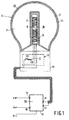
- Fig. 1 shows an embodiment of the illumination unit with the electrodeless lamp in longitudinal section, the supply being indicated diagrammatically,
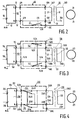
- Fig. 2 is the circuit diagram of the illumination unit of Fig. 1, and
- Figs. 3 and 4 show the circuit diagrams of further embodiments of the illumination unit according to the invention.
- The illumination unit shown in Fig. 1 comprises an electrodeless low-
pressure discharge lamp 10. - The illumination unit is provided with a
lamp vessel 20 which encloses adischarge space 21 and contains an ionizable filling. Thelamp vessel 20 has at an inner surface 22 aluminescent layer 23 which comprises green-luminescing terbium-activated cerium-magnesium aluminate and red-luminescing yttrium oxide activated by trivalent europium. - The illumination unit is further provided with a
holder 60 for the lamp vessel, with acoil 30 for generating a high-frequency magnetic field so as to maintain an electric discharge in thedischarge space 21, and with a high-frequency supply 50 for thecoil 30. Thelamp vessel 20 may be detachably coupled to theholder 60. - The illumination unit is also provided with ignition aids 40 for promoting the initiation of the discharge.
- The
coil 30 has a primary 31 and a secondary winding 32 around acore 33 of soft-magnetic material, here of Philips 4C6 ferrite (diagrammatically indicated in Fig. 2). Alternatively, a core may be absent. In the embodiment shown, the primary and the secondary winding have the same winding direction. The primary winding 31 has a first and asecond end second contact supply 50. Thefirst contact 51 of thesupply 50 delivers a high-frequency voltage (V) relative to earth M. Thesecond contact 52 supplies a reference voltage (N) which is free from high-frequency variations. For the sake of clarity, the examples mentioned in the present description are based on the assumption that the reference voltage (N) is equal to 0. Thesupply 50 accommodated in an earthedhousing 53 furthermore has a first and asecond input terminal second end 34B in the primary winding 31. In the secondary winding 32, a voltage gradient over the interval (-V, 0) is generated in a direction from a first 35A to asecond end 35B which is opposed to the voltage gradient from the first to thesecond end - In the nominal operational state, the
second end 35B of the secondary winding 32 is connected to thesecond contact 52 of thesupply 50 via thefirst switch 41 which is then in a closed state (shown with a broken line as 41B), switch 41 being a bimetal switch here. Thesecond end 35B accordingly has a voltage 0. Thefirst end 35A has a voltage -V. In the nominal operational state, the voltage in the secondary winding 32 shows a gradient from the reference potential to a value which is approximately as great as, but of opposite sign to, that of thefirst end 34A of the primary winding 31. High-frequency variations of the voltage averaged over the joint surface area of the primary and of the secondary winding 31, 32 are then at least substantially absent. Contributions to the electric field as a result of high-frequency voltage differences between thewindings - The ignition aids 40 achieve that, after switching-on of the illumination unit, the nominal operational state is preceded by an ignition state in which the
second end 35B of the secondary winding 32 is disconnected from thesecond contact 52 of thesupply 50. This is realised in the present case in that thefirst switch 41 is then in anopen state 41A. - In the embodiment shown, the secondary winding 32 is decoupled in the ignition state.
- The moment of transition from the ignition state to the nominal operational state is dependent on a lamp parameter, here a temperature of the lamp. At a sufficiently high temperature, the
first switch 41 enters theclosed state 41B, as a result of which the illumination unit passes from the ignition state into the nominal operational state. - Since the
first switch 41 is open in the ignition state, no charge transport is possible anymore from or to the secondary winding 32 in this state. The average voltage of the secondary winding 32 cannot change then, so that it cannot compensate any high-frequency variations in the primary winding 31. - The electrodeless low-
pressure discharge lamp 10 and thesupply 50 are detachable from one another in the embodiment shown. The ignition aids 40 are accommodated in thelamp 10, i.e. in theholder 60 here. Thelamp 10 of this embodiment is provided withcontact elements 47A and 47B which are to be connected torespective contacts supply 50. - Alternatively, the
supply 50 together with the ignition aids 40 may form a supply device which is provided withoutput terminals 48A and 48B to which ends 34A and 34B of the primary winding 31 are to be connected, and with anoutput terminal 48C for connection to theend 35B of the secondary winding 32. - An embodiment of the supply device, furthermore, comprises the
coil 30. - In Fig. 3. components corresponding to those of Fig. 2 have reference numerals which are 100 higher. This Figure shows the circuit diagram of a further embodiment of the illumination unit according to the invention. In this embodiment, the illumination unit has in addition to the first switch 141 a
second switch 142 which is arranged between thefirst contact 151 of thesupply 150 and thefirst end 135A of the secondary winding 132 and which is closed (position 142A) in the ignition state and open (position 142B, in broken line) in the nominal operational state. - In the ignition state, a voltage gradient over the interval (V, 0) occurs in a direction from the first to the
second end 134A, 134B of the primary winding 31. Between the first and thesecond end 135, 135B of the secondary winding 132 the voltage curve covers the interval (V, 2V). The voltage value averaged over the joint surface area of thewindings windings - In what position the first and the
second switches switches positions - A supply device comprising a
supply 150 and ignition aids 140 has, besides theoutput terminals 148A-C mentioned above, also an output terminal 148D forend 135A of the secondary winding 132. - In Fig. 4, components corresponding to those of Fig. 2 have reference numerals which are 200 higher. An end 235Q of the secondary winding 232 is connected to an end 234Q of the primary winding 231 facing towards an opposed coil end. The
windings supply 250 via switchingelements elements occupy positions windings Ends 235Q, 235P thus form the first and the second end, respectively, in the ignition state. - In this state, the voltage in the primary winding 231 covers the interval (V, 0). The first end 235Q of the secondary winding 232 has a voltage V. A potential of 2V is generated in the
second end 235P of the secondary winding 232, which in this state is the end which is detached from the second contact 252 of thesupply 250. The contribution to the electric field caused by high-frequency variations in the voltage difference between the primary winding 231 and earth M is reinforced by a contribution caused by high-frequency variations in the voltage difference between the secondary winding 232 and earth M. - The
switches ends 234P and 234Q form the first and the second end, respectively, of the primary winding 231. Between theseends 234P, 234Q, the voltage covers the interval (V, 0). The first and the second end of the secondary winding 232 are formed byend 235P and end 235Q, respectively, in this state. The second end in this state is the end 235Q which is connected to the second contact 252 of thesupply 250. Between these ends, the voltage gradient is from 0 to -V. In this state, contributions to the electric field caused by high-frequency voltage differences between thewindings - In a modification, for example a modification of one of the above embodiments, the windings have mutually opposed winding directions. In this modification, the voltage gradient in the secondary winding relative to the coil axis is opposed to that in the primary winding. The direction from the first to the second end in the secondary winding in this modification corresponds to the direction from the first to the second end in the primary winding. In a cylindrical coil, the first ends of the windings will be facing the same end of the coil.
- Three illumination units were manufactured in order to investigate the ignition characteristics of the lamp of the illumination unit according to the invention. The three illumination units each comprise a supply which delivers an AC voltage with a frequency of 2.65 MHz. The windings of the coil (referred to as coil I hereinafter) comprise five segments of 1, 2, 4, 9, and 3 turns in that order, with lengths of 2, 3, 7, 15, and 5 mm. The last segment lies just beyond the end of the core. Said segments have interspacings of 3, 6, 10, and 3 mm, respectively. The lamp vessel contains a filling of 3 mg Hg, Ar with a filling pressure of 33 Pa and ⁸⁵Kr at a partial pressure of 50 Torr. In the first illumination unit, the windings of the coil are connected as in the known illumination unit. In the second illumination unit, the windings are connected as in the ignition state of the embodiment (I) of the invention described with reference to Figs. 1 and 2. In the third illumination unit, the coil is connected in accordance with the ignition state of the embodiment (II) of Fig. 3. The ignition voltage was also measured in the three illumination units mentioned with no mercury in the lamp vessel. The ignition voltage was determined in that the amplitude of the voltage applied to the first contact of the supply was increased until the lamp ignited. The measurements were repeated for a coil whose windings comprise 17 turns each, evenly spread over the core. This coil has been indicated with coil II hereinafter.
The results are shown in the following Table.
It is evident from the Table that, with the use of the same coil type and the same filling, a lamp according to the first embodiment of the invention already has a considerably lower ignition voltage than a lamp without ignition aids. A lamp according to the second embodiment of the invention has an ignition voltage which is even approximately 60% lower than that of a lamp without ignition aids. The measure according to the invention accordingly leads to a reduction in the ignition voltage which is of the same order of magnitude as that of the known lamp, while nevertheless adverse effects of this measure can be easily avoided because the illumination unit need dwell in the ignition state for a comparatively short period only.
Claims (11)
- An illumination unit comprising an electrodeless low-pressure discharge lamp,
which illumination unit is provided with
a lamp vessel enclosing a discharge space which contains an ionizable filling,
a holder for the lamp vessel,
a coil for generating a high-frequency magnetic field for maintaining an electric discharge in the discharge space,
a high-frequency supply for the coil, and
ignition aids for promoting an initiation of the discharge,
which coil is provided with a primary and a secondary winding, the primary winding having a first and a second end which are connected to a first and a second contact, respectively, of the supply, while in a nominal operational state of the illumination unit the first contact supplies a high-frequency voltage and the second contact supplies a reference voltage free from high-frequency variations, in which state a voltage gradient arises in the primary winding in a direction from the first to the second end, and in the secondary winding a voltage gradient is generated in a direction from a first to a second end which is opposed to that from the first to the second end in the primary winding, while high-frequency variations of the voltage averaged over the joint surface area of the primary and the secondary winding are comparatively small in relation to high-frequency variations of the voltage averaged over the surface area of the primary winding, characterized in that, after switching-on, the ignition aids achieve that the nominal operational state is preceded by an ignition state in which the second end of the secondary winding is disconnected from the second contact of the supply unit. - An illumination unit as claimed in Claim 1, characterized in that the ignition aids between the second end of the secondary winding and the second contact of the supply comprise a first switch which is open in the ignition state and closed in the nominal operational state.
- An illumination unit as claimed in Claim 2, characterized in that the secondary winding is decoupled in the ignition state.
- An illumination unit as claimed in Claim 2, characterized in that the ignition aids in addition comprise a second switch, which is closed in the ignition state and open in the nominal operational state, between the first contact of the supply and the first end of the secondary winding.
- An illumination unit as claimed in any one of the Claims 1 to 4, characterized in that the transition from the ignition state to the nominal operational state is dependent on a lamp parameter.
- An illumination unit as claimed in Claim 5, characterized in that said lamp parameter is a temperature.
- An illumination unit as claimed in Claim 5, characterized in that said lamp parameter is light generated by the lamp.
- An electrodeless low-pressure discharge lamp suitable for use in an illumination unit as claimed in any one of the Claims 1 to 7, which lamp is provided with the lamp vessel, the holder, the coil, and the ignition aids.
- A holder suitable for use in an illumination unit as claimed in any one of the Claims 1 to 7, which holder is provided with the coil and with the ignition aids, and to which holder the lamp vessel can be coupled.
- A supply device suitable for use in an illumination unit as claimed in any one of the Claims 1 to 7, which supply device is provided with the high-frequency supply and with the ignition aids.
- A supply device as claimed in Claim 10, characterized in that the supply device is in addition provided with the coil.
Applications Claiming Priority (2)
| Application Number | Priority Date | Filing Date | Title |
|---|---|---|---|
| BE9301409A BE1007878A3 (en) | 1993-12-17 | 1993-12-17 | LIGHTING UNIT, AND electrodeless low-pressure discharge lamp HOLDER AND POWER DEVICE DESIGNED FOR USE IN LIGHTING UNIT. |
| BE9301409 | 1993-12-17 |
Publications (3)
| Publication Number | Publication Date |
|---|---|
| EP0658922A2 true EP0658922A2 (en) | 1995-06-21 |
| EP0658922A3 EP0658922A3 (en) | 1995-08-30 |
| EP0658922B1 EP0658922B1 (en) | 1997-06-18 |
Family
ID=3887653
Family Applications (1)
| Application Number | Title | Priority Date | Filing Date |
|---|---|---|---|
| EP94203582A Expired - Lifetime EP0658922B1 (en) | 1993-12-17 | 1994-12-09 | Illumination unit; and electrodeless low-pressure discharge lamp, holder, and supply unit suitable for use in the illumination unit |
Country Status (5)
| Country | Link |
|---|---|
| US (1) | US5650695A (en) |
| EP (1) | EP0658922B1 (en) |
| JP (1) | JPH07211471A (en) |
| BE (1) | BE1007878A3 (en) |
| DE (1) | DE69403884T2 (en) |
Cited By (3)
| Publication number | Priority date | Publication date | Assignee | Title |
|---|---|---|---|---|
| US5726523A (en) * | 1996-05-06 | 1998-03-10 | Matsushita Electric Works Research & Development Labratory | Electrodeless fluorescent lamp with bifilar coil and faraday shield |
| WO2001041515A1 (en) * | 1999-12-02 | 2001-06-07 | Koninklijke Philips Electronics N.V. | Induction lamp system and induction lamp |
| EP1587134A3 (en) * | 2004-04-16 | 2010-01-06 | Osram Sylvania Inc. | RF Induction lamp with reduced electromagnetic interference |
Families Citing this family (2)
| Publication number | Priority date | Publication date | Assignee | Title |
|---|---|---|---|---|
| CN1321331A (en) * | 1999-10-18 | 2001-11-07 | 松下电器产业株式会社 | Device for driving electrodeless discharge lamp |
| CN105895498A (en) * | 2016-05-18 | 2016-08-24 | 胡振华 | Low-voltage startup gas discharge lighting lamp |
Citations (2)
| Publication number | Priority date | Publication date | Assignee | Title |
|---|---|---|---|---|
| JPS5566854A (en) * | 1978-11-10 | 1980-05-20 | Mitsubishi Electric Corp | No-electrode fluorescent lamp apparatus |
| EP0332263A1 (en) * | 1988-03-09 | 1989-09-13 | Koninklijke Philips Electronics N.V. | Electrodeless low-pressure discharge lamp |
Family Cites Families (3)
| Publication number | Priority date | Publication date | Assignee | Title |
|---|---|---|---|---|
| DE69109333T2 (en) * | 1990-02-14 | 1996-01-04 | Philips Electronics Nv | Switching arrangement. |
| US5059868A (en) * | 1990-05-23 | 1991-10-22 | General Electric Company | Starting circuit for an electrodeless high intensity discharge lamp |
| US5175476A (en) * | 1992-04-16 | 1992-12-29 | General Electric Company | Magnetically tunable starting circuit for an electrodeless high intensity discharge lamp |
-
1993
- 1993-12-17 BE BE9301409A patent/BE1007878A3/en not_active IP Right Cessation
-
1994
- 1994-12-09 EP EP94203582A patent/EP0658922B1/en not_active Expired - Lifetime
- 1994-12-09 DE DE69403884T patent/DE69403884T2/en not_active Expired - Fee Related
- 1994-12-19 JP JP6314991A patent/JPH07211471A/en active Pending
-
1996
- 1996-01-02 US US08/587,599 patent/US5650695A/en not_active Expired - Fee Related
Patent Citations (2)
| Publication number | Priority date | Publication date | Assignee | Title |
|---|---|---|---|---|
| JPS5566854A (en) * | 1978-11-10 | 1980-05-20 | Mitsubishi Electric Corp | No-electrode fluorescent lamp apparatus |
| EP0332263A1 (en) * | 1988-03-09 | 1989-09-13 | Koninklijke Philips Electronics N.V. | Electrodeless low-pressure discharge lamp |
Non-Patent Citations (1)
| Title |
|---|
| PATENT ABSTRACTS OF JAPAN vol. 4, no. 109 (E-020) 6 August 1980 & JP-A-55 066 854 (MITSUBISHI ELECTRIC) 20 May 1980 * |
Cited By (3)
| Publication number | Priority date | Publication date | Assignee | Title |
|---|---|---|---|---|
| US5726523A (en) * | 1996-05-06 | 1998-03-10 | Matsushita Electric Works Research & Development Labratory | Electrodeless fluorescent lamp with bifilar coil and faraday shield |
| WO2001041515A1 (en) * | 1999-12-02 | 2001-06-07 | Koninklijke Philips Electronics N.V. | Induction lamp system and induction lamp |
| EP1587134A3 (en) * | 2004-04-16 | 2010-01-06 | Osram Sylvania Inc. | RF Induction lamp with reduced electromagnetic interference |
Also Published As
| Publication number | Publication date |
|---|---|
| EP0658922B1 (en) | 1997-06-18 |
| JPH07211471A (en) | 1995-08-11 |
| US5650695A (en) | 1997-07-22 |
| BE1007878A3 (en) | 1995-11-07 |
| DE69403884D1 (en) | 1997-07-24 |
| DE69403884T2 (en) | 1998-01-02 |
| EP0658922A3 (en) | 1995-08-30 |
Similar Documents
| Publication | Publication Date | Title |
|---|---|---|
| US5465028A (en) | Illumination unit, and electrodeless low-pressure discharge lamp and coil suitable for use therein | |
| EP0332263B1 (en) | Electrodeless low-pressure discharge lamp | |
| US4415838A (en) | Frequency converter for supplying an electrodeless discharge lamp | |
| US5325024A (en) | Light source including parallel driven low pressure RF fluorescent lamps | |
| US4422017A (en) | Electrodeless gas discharge lamp | |
| US5600208A (en) | Discharge lamp unit having separable high-voltage transformer safeguard | |
| US4253047A (en) | Starting electrodes for solenoidal electric field discharge lamps | |
| US4751435A (en) | Dual cathode beam mode fluorescent lamp with capacitive ballast | |
| US5650695A (en) | Illumination unit; and electrodeless low-pressure discharge lamp, holder, and supply unit suitable for use in the illumination unit | |
| EP0439863B1 (en) | Circuit arrangement | |
| EP0439864A1 (en) | Circuit arrangement | |
| US6051922A (en) | Electrodeless low-pressure mercury vapour discharge lamp employing a high frequency magnetic field having a layer of aluminum oxide particles | |
| CA2082713A1 (en) | Self-extinguishing gas probe starter for an electrodeless high intensity discharge lamp | |
| US4409521A (en) | Fluorescent lamp with reduced electromagnetic interference | |
| CA1217807A (en) | Magnetic fluorescent lamp | |
| EP0594245B1 (en) | Illumination unit and electrodeless low-pressure discharge lamp suitable for use therein | |
| EP0449639B1 (en) | Biasing system for reducing ion loss in lamps | |
| GB2066559A (en) | Fluorescent lamp with reduced electromagnetic interference | |
| GB2050685A (en) | Electrodeless discharge lamps | |
| EP0594247B1 (en) | Illumination unit and electrodeless low-pressure discharge lamp suitable for use therein | |
| EP0734585B1 (en) | Lighting unit, electrodeless low-pressure discharge lamp, and discharge vessel for use in a lighting unit | |
| US8487544B2 (en) | Power splitter circuit for electrodeless lamp | |
| JP3090323B2 (en) | High power magnetron | |
| CA1144226A (en) | Starting electrodes for solenoidal electric field discharge lamps | |
| EP0674339A2 (en) | Electrodeless low-pressure mercury vapour discharge lamp |
Legal Events
| Date | Code | Title | Description |
|---|---|---|---|
| PUAI | Public reference made under article 153(3) epc to a published international application that has entered the european phase |
Free format text: ORIGINAL CODE: 0009012 |
|
| AK | Designated contracting states |
Kind code of ref document: A2 Designated state(s): BE DE ES FR GB IT NL |
|
| PUAL | Search report despatched |
Free format text: ORIGINAL CODE: 0009013 |
|
| AK | Designated contracting states |
Kind code of ref document: A3 Designated state(s): BE DE ES FR GB IT NL |
|
| 17P | Request for examination filed |
Effective date: 19960229 |
|
| GRAG | Despatch of communication of intention to grant |
Free format text: ORIGINAL CODE: EPIDOS AGRA |
|
| 17Q | First examination report despatched |
Effective date: 19960820 |
|
| GRAH | Despatch of communication of intention to grant a patent |
Free format text: ORIGINAL CODE: EPIDOS IGRA |
|
| GRAH | Despatch of communication of intention to grant a patent |
Free format text: ORIGINAL CODE: EPIDOS IGRA |
|
| GRAA | (expected) grant |
Free format text: ORIGINAL CODE: 0009210 |
|
| AK | Designated contracting states |
Kind code of ref document: B1 Designated state(s): BE DE ES FR GB IT NL |
|
| PG25 | Lapsed in a contracting state [announced via postgrant information from national office to epo] |
Ref country code: NL Free format text: LAPSE BECAUSE OF FAILURE TO SUBMIT A TRANSLATION OF THE DESCRIPTION OR TO PAY THE FEE WITHIN THE PRESCRIBED TIME-LIMIT Effective date: 19970618 Ref country code: IT Free format text: LAPSE BECAUSE OF FAILURE TO SUBMIT A TRANSLATION OF THE DESCRIPTION OR TO PAY THE FEE WITHIN THE PRE;WARNING: LAPSES OF ITALIAN PATENTS WITH EFFECTIVE DATE BEFORE 2007 MAY HAVE OCCURRED AT ANY TIME BEFORE 2007. THE CORRECT EFFECTIVE DATE MAY BE DIFFERENT FROM THE ONE RECORDED.SCRIBED TIME-LIMIT Effective date: 19970618 Ref country code: ES Free format text: THE PATENT HAS BEEN ANNULLED BY A DECISION OF A NATIONAL AUTHORITY Effective date: 19970618 Ref country code: BE Effective date: 19970618 |
|
| REF | Corresponds to: |
Ref document number: 69403884 Country of ref document: DE Date of ref document: 19970724 |
|
| ET | Fr: translation filed | ||
| NLV1 | Nl: lapsed or annulled due to failure to fulfill the requirements of art. 29p and 29m of the patents act | ||
| PLBE | No opposition filed within time limit |
Free format text: ORIGINAL CODE: 0009261 |
|
| STAA | Information on the status of an ep patent application or granted ep patent |
Free format text: STATUS: NO OPPOSITION FILED WITHIN TIME LIMIT |
|
| 26N | No opposition filed | ||
| REG | Reference to a national code |
Ref country code: FR Ref legal event code: CD |
|
| REG | Reference to a national code |
Ref country code: GB Ref legal event code: IF02 |
|
| REG | Reference to a national code |
Ref country code: GB Ref legal event code: 746 Effective date: 20020918 |
|
| REG | Reference to a national code |
Ref country code: FR Ref legal event code: D6 |
|
| PGFP | Annual fee paid to national office [announced via postgrant information from national office to epo] |
Ref country code: FR Payment date: 20021223 Year of fee payment: 9 |
|
| PGFP | Annual fee paid to national office [announced via postgrant information from national office to epo] |
Ref country code: GB Payment date: 20021224 Year of fee payment: 9 |
|
| PGFP | Annual fee paid to national office [announced via postgrant information from national office to epo] |
Ref country code: DE Payment date: 20030217 Year of fee payment: 9 |
|
| PG25 | Lapsed in a contracting state [announced via postgrant information from national office to epo] |
Ref country code: GB Free format text: LAPSE BECAUSE OF NON-PAYMENT OF DUE FEES Effective date: 20031209 |
|
| PG25 | Lapsed in a contracting state [announced via postgrant information from national office to epo] |
Ref country code: DE Free format text: LAPSE BECAUSE OF NON-PAYMENT OF DUE FEES Effective date: 20040701 |
|
| GBPC | Gb: european patent ceased through non-payment of renewal fee |
Effective date: 20031209 |
|
| PG25 | Lapsed in a contracting state [announced via postgrant information from national office to epo] |
Ref country code: FR Free format text: LAPSE BECAUSE OF NON-PAYMENT OF DUE FEES Effective date: 20040831 |
|
| REG | Reference to a national code |
Ref country code: FR Ref legal event code: ST |