EP0658386B1 - Foundry apparatus for automatic casting with pressurized ladle - Google Patents
Foundry apparatus for automatic casting with pressurized ladle Download PDFInfo
- Publication number
- EP0658386B1 EP0658386B1 EP94119601A EP94119601A EP0658386B1 EP 0658386 B1 EP0658386 B1 EP 0658386B1 EP 94119601 A EP94119601 A EP 94119601A EP 94119601 A EP94119601 A EP 94119601A EP 0658386 B1 EP0658386 B1 EP 0658386B1
- Authority
- EP
- European Patent Office
- Prior art keywords
- ladle
- carriage
- casting
- motorized
- guides
- Prior art date
- Legal status (The legal status is an assumption and is not a legal conclusion. Google has not performed a legal analysis and makes no representation as to the accuracy of the status listed.)
- Expired - Lifetime
Links
- 238000005266 casting Methods 0.000 title claims description 27
- IJGRMHOSHXDMSA-UHFFFAOYSA-N Atomic nitrogen Chemical compound N#N IJGRMHOSHXDMSA-UHFFFAOYSA-N 0.000 claims description 6
- 238000011081 inoculation Methods 0.000 claims description 5
- 241000842962 Apoda limacodes Species 0.000 claims description 4
- VNWKTOKETHGBQD-UHFFFAOYSA-N methane Chemical compound C VNWKTOKETHGBQD-UHFFFAOYSA-N 0.000 claims description 4
- 229910052757 nitrogen Inorganic materials 0.000 claims description 3
- 239000002184 metal Substances 0.000 description 5
- 230000008901 benefit Effects 0.000 description 3
- 239000007789 gas Substances 0.000 description 2
- 238000004519 manufacturing process Methods 0.000 description 2
- 239000000463 material Substances 0.000 description 2
- 230000003287 optical effect Effects 0.000 description 2
- 229910000831 Steel Inorganic materials 0.000 description 1
- 230000002411 adverse Effects 0.000 description 1
- 230000008878 coupling Effects 0.000 description 1
- 238000010168 coupling process Methods 0.000 description 1
- 238000005859 coupling reaction Methods 0.000 description 1
- 238000007599 discharging Methods 0.000 description 1
- 239000002054 inoculum Substances 0.000 description 1
- 230000000670 limiting effect Effects 0.000 description 1
- 238000002844 melting Methods 0.000 description 1
- 230000008018 melting Effects 0.000 description 1
- 238000000034 method Methods 0.000 description 1
- 238000012986 modification Methods 0.000 description 1
- 230000004048 modification Effects 0.000 description 1
- 239000011819 refractory material Substances 0.000 description 1
- 239000010959 steel Substances 0.000 description 1
- 230000007306 turnover Effects 0.000 description 1
Images

Classifications
-
- B—PERFORMING OPERATIONS; TRANSPORTING
- B22—CASTING; POWDER METALLURGY
- B22D—CASTING OF METALS; CASTING OF OTHER SUBSTANCES BY THE SAME PROCESSES OR DEVICES
- B22D37/00—Controlling or regulating the pouring of molten metal from a casting melt-holding vessel
Definitions
- the present invention relates to a foundry apparatus for automatic casting with pressurized ladle.
- This pressurized ladle includes a steel plate container which is internally lined with refractory material and has a hermetic upper lid provided with means for discharging and introducing pressurized gas.
- Two siphons one for loading and one for casting, are connected below the container and extend upwards.
- the first siphon has, in an upward region, a funnel-shaped loading mouth; the second siphon is instead provided with a basin with a casting hole in an upward region.
- the ladle includes optical devices for controlling the level in the runner and a plug for closing the casting hole.
- the molten metal is loaded by means of a secondary ladle which is appropriately removed from a melting furnace.
- pressurized gas is injected therein; this reduces the internal level and raises the levels in the siphons and therefore in the runner.
- the level control device combined with the plug for opening and closing the casting hole, allows the material to be cast into a die arranged below.
- Casting currently occurs by keeping the ladle fixed and by providing casting dies which are arranged in series and movable along a rail.
- the assembly is conveniently moved by one step so as to position the next die for casting.
- This fixed-ladle system is in any case a poorly flexible system from an operational point of view, since only the dies to be cast are movable, and production times are negatively affected if the movement is blocked for any reason.
- a principal aim of the present invention is therefore to provide a foundry apparatus for automatic casting with pressurized ladle that is more flexible in operation than current ones.
- a consequent primary object is to minimize downtimes.
- Another important object is to provide an apparatus that also allows to obtain qualitative benefits in the casting.
- Another object is to provide an apparatus that can be produced with conventional equipment.
- a foundry apparatus for automatic casting with pressurized ladle characterized in that it comprises a motorized means which cooperates with a casting line with dies and/or flaskless dies (motta) to be cast that are movable along first translatory guides, said motorized means being movable along second guides which are parallel and close to the first guides at a straight portion thereof, said motorized means furthermore supporting a pressurized ladle.
- a motorized means which cooperates with a casting line with dies and/or flaskless dies (motta) to be cast that are movable along first translatory guides, said motorized means being movable along second guides which are parallel and close to the first guides at a straight portion thereof, said motorized means furthermore supporting a pressurized ladle.
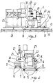
- a foundry apparatus comprises a casting line with dies 10 to be cast which are connected to each other in succession, are mounted on a carriage with wheels 11, and are movable along a rail track 12.
- a second track 13 lies parallel alongside said first track 12 at a straight portion thereof, and a carriage 15 is coupled thereon by means of wheels 14 so as to be movable; said carriage 15 is motorized with an electric gearmotor, not shown in the figures, whose speed can be adjusted with an inverter (this adjustment is possible with a remote control post).
- the carriage 15 has a strong metal structure with two spaced vertical posts 16 between which a seat-shaped base 18 is rotatably coupled above a horizontal axis 17; said base usually rests downwardly on the structure of said carriage 15.
- the seat-shaped base 18 is rotated by means of a hydraulic cylinder 19 which is mounted between an arm 20 thereof, which is arranged radially with respect to the axis 17, and the carriage 15.
- a pressurized ladle 21 is seated on the base 18 on self-centering locators, not shown in the figures, and is provided with nitrogen feeding systems equipped with a quick coupling.
- the ladle is per se known and is of the type described in the previously mentioned Italian patent no. 1,225,409.
- the parts of the ladle 21 that are visible in the figures are the container 23 with the lid 24, a loading funnel 25, and a runner 26 with its plug 27.
- the runner 26 protrudes from the second track 13 and is arranged above the region where the dies 10 pass at the casting holes.
- a cantilevered structure 28 is rigidly coupled to the structure of the carriage 15 within the dimensions of the rails of the second track 13, and a control booth 29 is placed on said structure; said booth supports, close to the ladle 21, a per se known threading inoculation system 30, with the associated inoculant reserve tank and infrared optical sensor for adjusting and synchronizing the casting operation.
- the inoculation system 30 is controlled by the control post by means of mechanical and electrical connections.
- a festoon guide not shown in the figures for the sake of simplicity, with festoons carried by carriages on an appropriate overhead rail, is provided to supply electric power, nitrogen, air, and methane to the carriage 15.
- pressurized ladle is movable along guides in this apparatus makes the assembly particularly flexible from an operational point of view.
- This method minimizes downtimes and the time for which the molten metal remains inside the ladle.
- Another advantage is that it is possible to replace the casting ladle without tampering with or disassembling any part of the carriage.
- the ladle is allowed to turn over in order to reduce the lateral bulk, placing the runner 26 in the space between the rails of the second track 13.
- the apparatus is adapted not only for casting lines formed by casting boxes but also for casting lines formed by flaskless dies with a continuous or intermittent carousel.
- the materials employed may be any according to the requirements.
Landscapes
- Engineering & Computer Science (AREA)
- Mechanical Engineering (AREA)
- Casting Support Devices, Ladles, And Melt Control Thereby (AREA)
- Producing Shaped Articles From Materials (AREA)
- Sorption Type Refrigeration Machines (AREA)
- Casting Devices For Molds (AREA)
Applications Claiming Priority (2)
| Application Number | Priority Date | Filing Date | Title |
|---|---|---|---|
| ITPD930242 | 1993-12-15 | ||
| ITPD930242A IT1263419B (it) | 1993-12-15 | 1993-12-15 | Impianto di fonderia per la colata automatica con siviera a pressione |
Publications (3)
| Publication Number | Publication Date |
|---|---|
| EP0658386A2 EP0658386A2 (en) | 1995-06-21 |
| EP0658386A3 EP0658386A3 (en) | 1995-11-15 |
| EP0658386B1 true EP0658386B1 (en) | 1999-07-14 |
Family
ID=11390500
Family Applications (1)
| Application Number | Title | Priority Date | Filing Date |
|---|---|---|---|
| EP94119601A Expired - Lifetime EP0658386B1 (en) | 1993-12-15 | 1994-12-12 | Foundry apparatus for automatic casting with pressurized ladle |
Country Status (4)
| Country | Link |
|---|---|
| EP (1) | EP0658386B1 (it) |
| DE (1) | DE69419486T2 (it) |
| ES (1) | ES2133469T3 (it) |
| IT (1) | IT1263419B (it) |
Family Cites Families (5)
| Publication number | Priority date | Publication date | Assignee | Title |
|---|---|---|---|---|
| GB1435871A (en) * | 1973-06-21 | 1976-05-19 | Gen Motors Corp | Continuous mechanicaltiron pouring line |
| IT1010974B (it) * | 1974-03-27 | 1977-01-20 | Forcesi Oppi G | Macchina per introdurre a bassa pressione metallo fuso in stampi |
| DE2543168C3 (de) * | 1975-09-27 | 1980-05-29 | Brown, Boveri & Cie Ag, 6800 Mannheim | Fahrbare Gießvorrichtung |
| CH629130A5 (fr) * | 1979-06-07 | 1982-04-15 | Mezger Ed Maschinenfabrik & Ei | Installation de coulee a commande automatique. |
| CH647435A5 (en) * | 1980-07-11 | 1985-01-31 | Fischer Ag Georg | Continuous-flow vessel for positioning between a casting ladle and casting mould |
-
1993
- 1993-12-15 IT ITPD930242A patent/IT1263419B/it active IP Right Grant
-
1994
- 1994-12-12 ES ES94119601T patent/ES2133469T3/es not_active Expired - Lifetime
- 1994-12-12 DE DE69419486T patent/DE69419486T2/de not_active Expired - Fee Related
- 1994-12-12 EP EP94119601A patent/EP0658386B1/en not_active Expired - Lifetime
Also Published As
| Publication number | Publication date |
|---|---|
| EP0658386A2 (en) | 1995-06-21 |
| EP0658386A3 (en) | 1995-11-15 |
| ITPD930242A0 (it) | 1993-12-15 |
| DE69419486D1 (de) | 1999-08-19 |
| IT1263419B (it) | 1996-08-05 |
| DE69419486T2 (de) | 1999-10-28 |
| ITPD930242A1 (it) | 1995-06-15 |
| ES2133469T3 (es) | 1999-09-16 |
Similar Documents
| Publication | Publication Date | Title |
|---|---|---|
| US4456054A (en) | Method and apparatus for horizontal continuous casting | |
| CA1057930A (en) | Pouring tube changing arrangement | |
| CN110681852B (zh) | 铸钢铸造物制造系统 | |
| EP0090490B1 (en) | A plant for the production of castings in a stepwise advanced casting mould consisting of identical, flaskless mould parts | |
| JPH09174229A (ja) | 自動注湯方法 | |
| US6619371B1 (en) | Method and device for controlling the movement of the teeming ladle having a low teeming height in a teeming installation device | |
| EP0658386B1 (en) | Foundry apparatus for automatic casting with pressurized ladle | |
| US5503215A (en) | Precision casting system with lock | |
| US4755137A (en) | Process and installation for maintaining the lining of a furnace shell | |
| US4230308A (en) | Automated casting line supply system | |
| US6440355B1 (en) | Apparatus for measuring bath level in a basic oxygen furnace to determine lance height adjustment | |
| US6929052B2 (en) | Method and apparatus for uphill casting with a slide valve closure placed on the casting table | |
| GB1513108A (en) | Pouring apparatus for dispensing molten material to a casting line | |
| EP1481749A1 (en) | Gravity casting apparatus with tilting die and method for gravity casting with tilting die | |
| KR100529588B1 (ko) | 연속주조설비에서 주형 장치의 교체 가능한 부분을교체하는 장치 및 방법 | |
| US3685573A (en) | Movable casting apparatus | |
| KR20240039159A (ko) | 턴디쉬 유닛용 변경 시스템, 변경 시스템용 턴디쉬 유닛, 분무화 설비 및 금속 용융물 분무화 방법 | |
| EP0104392B1 (en) | Method of producing nodular iron and a machine for the implementation thereof | |
| KR100525600B1 (ko) | 연속주조용 용강 주입장치 | |
| JPS61172660A (ja) | 連続鋳造設備のノズル交換方法 | |
| US3433288A (en) | Continuous casting apparatus with tiltable intermediate ladle | |
| JP2830370B2 (ja) | 金属溶湯への線状添加剤の供給装置 | |
| CN111659878B (zh) | 一种铸造机 | |
| KR100301160B1 (ko) | 스트립 클래딩용 사이드 빔 장치 및 그 작업방법 | |
| JPH0139859B2 (it) |
Legal Events
| Date | Code | Title | Description |
|---|---|---|---|
| PUAI | Public reference made under article 153(3) epc to a published international application that has entered the european phase |
Free format text: ORIGINAL CODE: 0009012 |
|
| AK | Designated contracting states |
Kind code of ref document: A2 Designated state(s): DE ES FR |
|
| PUAL | Search report despatched |
Free format text: ORIGINAL CODE: 0009013 |
|
| RHK1 | Main classification (correction) |
Ipc: B22D 47/00 |
|
| AK | Designated contracting states |
Kind code of ref document: A3 Designated state(s): DE ES FR |
|
| 17P | Request for examination filed |
Effective date: 19960417 |
|
| 17Q | First examination report despatched |
Effective date: 19970912 |
|
| TPAD | Observations filed by third parties |
Free format text: ORIGINAL CODE: EPIDOS TIPA |
|
| GRAG | Despatch of communication of intention to grant |
Free format text: ORIGINAL CODE: EPIDOS AGRA |
|
| GRAG | Despatch of communication of intention to grant |
Free format text: ORIGINAL CODE: EPIDOS AGRA |
|
| GRAH | Despatch of communication of intention to grant a patent |
Free format text: ORIGINAL CODE: EPIDOS IGRA |
|
| GRAH | Despatch of communication of intention to grant a patent |
Free format text: ORIGINAL CODE: EPIDOS IGRA |
|
| GRAA | (expected) grant |
Free format text: ORIGINAL CODE: 0009210 |
|
| AK | Designated contracting states |
Kind code of ref document: B1 Designated state(s): DE ES FR |
|
| REF | Corresponds to: |
Ref document number: 69419486 Country of ref document: DE Date of ref document: 19990819 |
|
| ET | Fr: translation filed | ||
| REG | Reference to a national code |
Ref country code: ES Ref legal event code: FG2A Ref document number: 2133469 Country of ref document: ES Kind code of ref document: T3 |
|
| PLBE | No opposition filed within time limit |
Free format text: ORIGINAL CODE: 0009261 |
|
| STAA | Information on the status of an ep patent application or granted ep patent |
Free format text: STATUS: NO OPPOSITION FILED WITHIN TIME LIMIT |
|
| 26N | No opposition filed | ||
| PGFP | Annual fee paid to national office [announced via postgrant information from national office to epo] |
Ref country code: FR Payment date: 20051213 Year of fee payment: 12 |
|
| PGFP | Annual fee paid to national office [announced via postgrant information from national office to epo] |
Ref country code: ES Payment date: 20051214 Year of fee payment: 12 |
|
| PGFP | Annual fee paid to national office [announced via postgrant information from national office to epo] |
Ref country code: DE Payment date: 20060130 Year of fee payment: 12 |
|
| PG25 | Lapsed in a contracting state [announced via postgrant information from national office to epo] |
Ref country code: DE Free format text: LAPSE BECAUSE OF NON-PAYMENT OF DUE FEES Effective date: 20070703 |
|
| REG | Reference to a national code |
Ref country code: FR Ref legal event code: ST Effective date: 20070831 |
|
| REG | Reference to a national code |
Ref country code: ES Ref legal event code: FD2A Effective date: 20061213 |
|
| PG25 | Lapsed in a contracting state [announced via postgrant information from national office to epo] |
Ref country code: FR Free format text: LAPSE BECAUSE OF NON-PAYMENT OF DUE FEES Effective date: 20070102 Ref country code: ES Free format text: LAPSE BECAUSE OF NON-PAYMENT OF DUE FEES Effective date: 20061213 |