EP0658244B1 - System for varying light intensity such as for use in motion picture photography - Google Patents
System for varying light intensity such as for use in motion picture photography Download PDFInfo
- Publication number
- EP0658244B1 EP0658244B1 EP93914316A EP93914316A EP0658244B1 EP 0658244 B1 EP0658244 B1 EP 0658244B1 EP 93914316 A EP93914316 A EP 93914316A EP 93914316 A EP93914316 A EP 93914316A EP 0658244 B1 EP0658244 B1 EP 0658244B1
- Authority
- EP
- European Patent Office
- Prior art keywords
- density
- section
- filter
- neutral density
- neutral
- Prior art date
- Legal status (The legal status is an assumption and is not a legal conclusion. Google has not performed a legal analysis and makes no representation as to the accuracy of the status listed.)
- Expired - Lifetime
Links
- 230000033001 locomotion Effects 0.000 title abstract description 5
- 230000007935 neutral effect Effects 0.000 claims abstract description 99
- 238000000034 method Methods 0.000 claims abstract description 7
- 230000007246 mechanism Effects 0.000 claims description 14
- 230000008859 change Effects 0.000 claims description 12
- 230000005540 biological transmission Effects 0.000 claims description 9
- 230000004044 response Effects 0.000 claims description 7
- 230000001276 controlling effect Effects 0.000 claims description 3
- 238000004891 communication Methods 0.000 claims description 2
- 230000001419 dependent effect Effects 0.000 claims description 2
- 230000001105 regulatory effect Effects 0.000 claims description 2
- 230000003287 optical effect Effects 0.000 claims 2
- 238000013461 design Methods 0.000 description 8
- 230000000694 effects Effects 0.000 description 6
- 238000001914 filtration Methods 0.000 description 5
- 239000000463 material Substances 0.000 description 4
- 230000009977 dual effect Effects 0.000 description 3
- 238000012937 correction Methods 0.000 description 2
- 230000003247 decreasing effect Effects 0.000 description 2
- 239000002184 metal Substances 0.000 description 2
- 239000000758 substrate Substances 0.000 description 2
- VYPSYNLAJGMNEJ-UHFFFAOYSA-N Silicium dioxide Chemical compound O=[Si]=O VYPSYNLAJGMNEJ-UHFFFAOYSA-N 0.000 description 1
- 238000000576 coating method Methods 0.000 description 1
- 239000005350 fused silica glass Substances 0.000 description 1
- 239000011521 glass Substances 0.000 description 1
- 150000004820 halides Chemical class 0.000 description 1
- 238000004519 manufacturing process Methods 0.000 description 1
- 238000012986 modification Methods 0.000 description 1
- 230000004048 modification Effects 0.000 description 1
- 238000002310 reflectometry Methods 0.000 description 1
- 230000035939 shock Effects 0.000 description 1
- 238000012360 testing method Methods 0.000 description 1
- 210000003813 thumb Anatomy 0.000 description 1
- 229910052724 xenon Inorganic materials 0.000 description 1
- FHNFHKCVQCLJFQ-UHFFFAOYSA-N xenon atom Chemical compound [Xe] FHNFHKCVQCLJFQ-UHFFFAOYSA-N 0.000 description 1
Images


Classifications
-
- F—MECHANICAL ENGINEERING; LIGHTING; HEATING; WEAPONS; BLASTING
- F21—LIGHTING
- F21V—FUNCTIONAL FEATURES OR DETAILS OF LIGHTING DEVICES OR SYSTEMS THEREOF; STRUCTURAL COMBINATIONS OF LIGHTING DEVICES WITH OTHER ARTICLES, NOT OTHERWISE PROVIDED FOR
- F21V9/00—Elements for modifying spectral properties, polarisation or intensity of the light emitted, e.g. filters
- F21V9/40—Elements for modifying spectral properties, polarisation or intensity of the light emitted, e.g. filters with provision for controlling spectral properties, e.g. colour, or intensity
-
- F—MECHANICAL ENGINEERING; LIGHTING; HEATING; WEAPONS; BLASTING
- F21—LIGHTING
- F21W—INDEXING SCHEME ASSOCIATED WITH SUBCLASSES F21K, F21L, F21S and F21V, RELATING TO USES OR APPLICATIONS OF LIGHTING DEVICES OR SYSTEMS
- F21W2131/00—Use or application of lighting devices or systems not provided for in codes F21W2102/00-F21W2121/00
- F21W2131/40—Lighting for industrial, commercial, recreational or military use
- F21W2131/406—Lighting for industrial, commercial, recreational or military use for theatres, stages or film studios
Definitions
- the field of the present invention relates to lighting apparatus such as may be particularly used for varying the intensity of light produced by a light source for use in motion picture photography such as film and video.
- the intensity may be varied by changing the power input to the light such as through a rheostat.
- the color quality or color temperature is also varied. Though such color change may not be perceptible to the human eye, color film is easily affected by color quality change.
- U.S. Patent No. 4,015,113 discloses a variable intensity light source in which light from a lighting element is directed against a reflector.
- the reflector has adjustable degrees cf reflectivity being comprised of a plurality of rotatable cylindrical rollers, each roller having half of its surface coated with a black, nonreflective material. As the rollers are rotated, the intensity of light is varied without changing color quality.
- Other devices have included shutter elements interposed in the light path, the elements opening or closing to vary the amount of light transmitted or reflected.
- US-A-4 984 143 discloses a light filtering system for use with a spot light.
- the filtering system consists of a filter module which includes three colour-specific filter elements and a colour neutral filter element.
- the filter elements can be formed by discs arranged so that a portion of their area interrupts the light beam.
- the filtering can vary circumferentially around the discs so that they have a clear section, and a section of gradually increasing density. Thus, rotation of the discs adjusts the degree of filtering.
- the discs are rotated by motors under the control of a computer.
- US-A-4 890 208 discloses stage lighting apparatus which, again, includes a filter unit with three colour-specific filter elements and one colour neutral filter element.
- the elements may be strips or discs which overlap and have a density which varies over their area so that the degree of filtering can be adjusted by moving the filter elements.
- the elements may be motor driven.
- a movie camera system having a camera housing with a picture recording mechanism, a lens system including a lens focusing mechanism, and a variable intensity lighting system, the variable intensity lighting system comprising:
- a method of varying the intensity of light from a light source for use in a camera system comprising the steps of:
- a lighting system comprising:
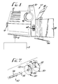
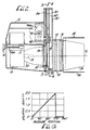
- Figs. 1-4 illustrate a lighting apparatus 10 which is mountable by a bracket 8 to suitable supporting location such as camera 5.
- the lighting apparatus 10 includes a main housing 12 with a front wheel housing 30, a filter housing 70, and the barn door assembly 82, 84, 86, 88 attached to the front thereof.
- Light is emitted from light source 18, which is typically an electric lamp.
- light source 18 typically an electric lamp.
- professional light sources employ a halide-metal (HMI) element, a xenon element, or a more standard lower output incandescent lamp.
- a light source 18 is positioned in the center of a reflector 20 which directs light from the light source 18 out along an outgoing light path 15.
- the relative axial position of the lighting element 18 to the reflector 20 may be adjusted by an adjustment mechanism consisting of an adjustment knob 16 attached to a screw 16a which axially translates a bracket 17.
- the bracket 17 is attached to the socket assembly carrier 14 into which the lamp 18 is plugged. Rotation of the knob 16 axially translates the socket carrier 14 thereby adjusting the relative position of the lamp 18 to the reflector 20 for focusing of the outgoing light beam along light path 15.
- a heat shield 34 which is typically a glass element designed to permit unaffected transmission of light but inhibit transmission of heat therethrough.
- the light Upon exiting heat shield 34, the light then passes through an aperture 36a in the back plate 36.
- the aperture 36a is a rectangular aperture of desired dimensions.
- the light then passes through a neutral density filter disk 50 positioned in front of the aperture 36a.
- the neutral density filter 50 is positioned so that light exiting through aperture 36a passes through a lower section of the neutral density filter disk 50.
- the disk 50 has a center hole 52 and is mounted to shaft 98 and flange 96 by a retainer ring 54.
- the disk 50 is rotatable through rotation of shaft 98.
- Drive shaft 98 is rotationally operated by a transmission 97 which is alternatively operated by a motor 94 or a manual drive shaft 92.
- the manual drive shaft 92 is operable on either side of the lighting apparatus 10 through operation of knobs 90, 90a.
- the motor 94 is controlled by a controller 100 which in turn is operable from a signal transmitter 110 described in more detail below.
- the controller 100 is also in communication with a transducer/limiter 99 which provides a signal indicating the angular position of the motor shaft 94a and consequently the angular position of the shaft 98 and the disk 50.
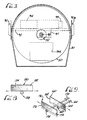
- the neutral density disk 50 is preferably designed as shown in Fig. 6 to have a clear section of 90° arc, the clear section having a relative density of approximately zero. Over an angular position from zero to 270°, the relative density of the disk 50 increases linearly from approximately zero to a relative density of about 2.0. In a preferred embodiment, the relative density increases linearly from approximately zero to approximately 3.0.
- the neutral density filter disk 50 linearly attenuates light passing therethrough with the relative angular disk position disk providing increasing or decreasing attenuation as a higher or lower density disk section is positioned in front of the aperture 36a through which the light passes.
- the neutral density filter is preferably designed to be relatively color neutral meaning that light passing therethrough does not change in color quality or color temperature.
- the neutral density disk has an outside diameter 175 mm and an inside center hole of approximately 25.4 mm.
- the disk is preferably constructed with a PyrexTM (or equivalent material) substrate which is coated with neutral density filter material to achieve a design with the desired light transmission characteristics.
- the substrate may be comprised of fused silica which is also a material which has a low thermal expansion coefficient and high thermal shock value.
- the disk is preferably designed to attenuate light without causing change in color quality or color temperature. Such a disk is available from Reynard Enterprises, Inc. of Website, California, USA.
- the signal element 110 and/or the controller 100 may be connected both to the motor 94 and another system actuator 115 such as the motor for the lens focusing system.
- the lighting apparatus control and the lens focusing system control each have two channels, each having control ranges separately set.
- a system may be calibrated with one end of the controller range setting the lighting apparatus at 20% intensity and the lens focus at 1 meter, the other end of the range being calibrated to be 80% for the lighting apparatus and the lens focus at 10 meters. Points in between the two limits are then interpolated by a suitable algorithm.
- Such a system allows for automatic adjustment of light intensity as tne lens is focused tracking the change in the distance to the subject.
- the signal element 110 such as a signal emitter may be a rotatable dial mounted on the lighting apparatus 10 itself or may be a radio-controlled apparatus located at some distance from the lighting apparatus 10.
- a signal produced from the actuator 115 may be taken from a camera lens focus mechanism such that the light intensity may be automatically varied as the camera lens is focused.
- the camera operator is continually adjusting the focus of the camera lens.
- the signal element 110 tied into the camera lens focus mechanism, the signal provided to the controller 100 from the signal element 110 permits automatic adjustment of the light intensity to compensate for the changing distance of the subject to the camera.
- the signal element 110 may be any desired signal generator providing a signal to controller 100 such as an electronic or radio-controlled actuator. Though a conventional analog signal may be used, a digitized signal may be employed to provide more precise control.
- the actuator 115 may be any suitable mechanism including a lens focus mechanism, a lens aperture adjustment device, camera shutter opening control device, or an automatic light exposure device.
- the light After passing through the neutral density disk 50, the light passes through a color wheel 60.
- the color wheel 60 has a center opening 62 which is mounted on shaft 98 by a retainer ring 64 with fitting 65 locking the elements in place.
- the color wheel 60 is essentially another filter disk having light transmission properties, such as achievable by special coatings, which alters the color quality of light passing therethrough by a desired amount.
- the color correct wheel 60 In similar geometry to the neutral density disk 50, the color correct wheel 60 has a 90° clear section and a 270° color correcting section of linearly increasing density from approximately a zero color quality correcting effect to a maximum desired color quality correction effect.
- color correction will be selected dependent upon the particular application.
- a typical lamp for a lighting apparatus is a halide metal variety in which the color temperature of a new lamp ranges from approximately 5600-6000°K. As the lamp ages, the color temperature drops such that after approximately 300-500 hours of use, the color temperature of the light produced has dropped to such a degree that it is unusable.
- the color correct wheel filter 60 will correct for this change in color temperature by allowing the user, by manipulation of thumb wheels 68, to rotate the color correct wheel 60 thereby selectively positioning a gradually increasing (or decreasing) color quality correcting effect in the outgoing light path.
- Such a disk is also available from Reynard Enterprises, Inc. of Website, California.
- a color correct wheel 60 may also be used to select the desired color temperature of light produced by the lighting apparatus 10 to provide desired lighting effects and to match or tune the light of the lighting apparatus 10 to other filming light sources.
- the color correct wheel 60 may be remotely controlled or otherwise linked to a desired output control. For example, the position of the color correct wheel 60 may be automatically adjusted to correct to correspond to lamp temperature or some other lighting factor.
- a conventional set of barn doors 82, 84, 86, 88 are positioned on the outer portion of the filter housing 70, the doors being pivotable to provide the desired aiming effect.
- the filters 72 and/or 74 may comprise a diffuser which will reflect and diffuse the light so as to compensate for any intensity imbalance across a light plane.
- Tables A, B, and C show test results of measured light intensities from a lighting apparatus as illustrated measured at a projection screen 6 feet (1.8 meters) and 12 feet (3.6 meters) from the lighting apparatus.
- Table A without a diffuser, at 50% attenuation the measured light intensity varies from 21 lumens on the left to 15 lumens on the right (at a distance of 6 feet (1.8 m)).
- Table B shows at 50% attenuation the relative intensity on the left is 9 lumens while the relative intensity at the right is 8.2 lumens. Such an intensity variation is within acceptable limits.
- FIG. 7 illustrates an alternative embodiment having two neutral density disks 120, 130 replacing the single neutral density disk 50 of the previous embodiment with a pair of disks 120, 130.
- the first and second disks 120, 130 are mounted on a shaft 140 having an internal rotational element 142 and an external rotational element 144.
- the first disk 120 has a clear section 122 and a linearly increasing neutral density section 124.
- the second disk 130 has a 90° clear section 132 and a 270° gradually linearly increasing neutral density section 134.
- the first disk 120 is mounted on the outer shaft element 144 and the second disk is mounted on the inner shaft element 142.
- the disks 120, 130 are counter-rotated and the neutral density sections 124, 134 are configured in opposite orientations so that during counter-rotation of the two disks 120, 130 there will be in summation approximately equal attenuation from left to right across the aperture 36a.
- a disk-shaped neutral density element is the preferred geometry, other geometries may be suitable depending upon the particular application.
- a rectangular neutral density element 150 has a clear section 152 and a gradually increasing neutral density section 154.
- the rectangular neutral density filter 150 is moved from side to side to provide the desired amount of attenuating filter medium in the light path.
- a dual rectangular filter design may be employed as illustrated in Fig. 9.
- a first rectangular neutral filter 160 having a clear section 162 and a gradually linearly increasing neutral density filter 164 is positioned in the light path with its clear section on the right side of the outgoing light.
- a second rectangular neutral density filter 170 is positioned adjacent the first rectangular neutral density filter 160.
- the second rectangular neutral density filter 170 has a clear section 172 and a linearly increasing neutral density section 174.
- the clear section of the second rectangular filter is positioned on the left side of the aperture.
- the position of the first rectangular filter 160 is changed by rotation of shaft 166 and gear 168.
- a conventional rack and pinion system may be provided to accomplish the desired movements.
- the shaft 176 and gear 178 controlling position of the second rectangular neutral density filter 170 rotate in the opposite directions to provide a balanced summation of attenuation of light passing through the two rectangular neutral density filters 160, 170.
- the color correct filter may be rectangular similar to the shape of the neutral density filter 150 illustrated in Fig. 8. Alternately, if the side to side (in the illustrated example left to right) unevenness in attenuation becomes too critical, two color correcting filters may be employed in a configuration similar to the neutral density disks of Figs. 7 or 9.
Landscapes
- Physics & Mathematics (AREA)
- Spectroscopy & Molecular Physics (AREA)
- Engineering & Computer Science (AREA)
- General Engineering & Computer Science (AREA)
- Blocking Light For Cameras (AREA)
- Mechanical Light Control Or Optical Switches (AREA)
- Liquid Crystal (AREA)
- Exposure Control For Cameras (AREA)
- Securing Globes, Refractors, Reflectors Or The Like (AREA)
- Focusing (AREA)
- Automatic Focus Adjustment (AREA)
- Stroboscope Apparatuses (AREA)
Abstract
Description
| Without diffuser | |||
| POSITION | |||
| Center | 2.1 meter left | 2.1 meter right | |
| FILTER DENSITY (%) | |||
| DISTANCE = 6 ft. (1.8 m) | |||
| 0% | 67 (lumens) | 31 | 33.4 |
| 50% | 33 | 21 | 15 |
| DISTANCE = 12 ft. (3.6 m) | |||
| Center | 2.1meter left | 2.1 meter right | |
| 0% | 17.4 | 8 | 9.5 |
| 50% | 8.7 | 5.8 | 3.4 |
| With one diffuser | |||
| POSITION | |||
| Center | 2.1 meter left | 2.1 meter right | |
| FILTER DENSITY (%) | |||
| DISTANCE = 6 ft. (1.8 m) | |||
| 0% | 30 (lumens) | 13.6 | 14 |
| 50% | 17 | 9 | 8.2 |
| DISTANCE = 12 ft. (3.6 m) | |||
| Center | 2.1 meter left | 2.1 meter right | |
| 0% | 7.7 | 3 | 4 |
| 50% | 3.9 | 1.9 | 1.9 |
| With two diffusers | |||
| POSITION | |||
| Center | 2.1 meter left | 2.1 meter right | |
| DENSITY (%) | |||
| DISTANCE = 6 ft. (1.8 m) | |||
| 0% | 16.3 (lumens) | 8.6 | 9.1 |
| 50% | 8.8 | 4.5 | 4.6 |
| DISTANCE = 12 ft. (3.6 m) | |||
| Center | 2.1 meter left | 2.1 meter right | |
| 0% | 4.3 | 2.0 | 2.5 |
| 50% | 2.2 | 1.1 | 1.2 |
Claims (20)
- A movie camera system having a camera housing with a picture recording mechanism, a lens system including a lens focusing mechanism (115), and a variable intensity lighting system, the variable intensity lighting system comprising:a light source (18),an outgoing aperture (36a),means (20) for directing light from the light source (18) along an outgoing light path through the outgoing aperture (36a),a primary movable neutral density filter (50,120,130) having a portion aligned in the outgoing light path, the neutral density filter (50,120,130) comprising a first clear section and a second neutral density section, the second neutral density section being variable, increasing in density from a near zero density at an interface with the first clear section to a selected higher density at an opposite end of the second neutral density section, the neutral density filter (50,120,130) being colour neutral;a diffuser positioned in the outing light path downstream of the neutral density filter; and a controller (100) for regulating the position of the primary movable neutral density filter (50,120,130) in response to adjustment of the lens focusing mechanism (115).
- A movie camera system according to claim 1, further comprising a secondary movable neutral density filter (130) positioned in series with the primary neutral density filter (120), the secondary neutral density filter (130) comprising a first clear section and a second neutral density section, the second neutral density section being continuously variable, gradually increasing in density from a near zero density at an interface with the first clear section to a selected higher density at an opposite end of the second neutral density section, wherein the secondary neutral density filter (130) is generally colour neutral, wherein the primary and secondary neutral density filters (120,130) are movable in opposite directions so as to achieve in summation therethrough approximately equal attenuation throughout the width of the light path.
- A movie camera system according to claim 1 or 2, wherein the second neutral density section is continuously variable, gradually increasing in density from said near zero density to said selected higher density.
- A movie camera system according to claim 1, 2 or 3, wherein the neutral density filter (50,120,130) comprises a circular disc positioned in a plane generally perpendicular to the outgoing light path, the circular disc having (a) a clear arcuate section and (b) a variable density arcuate section of gradually increasing density from a given first density at an interface with the clear arcuate section to a selected higher density at an opposite end of the variable density arcuate section.
- A movie camera system according to claim 4, wherein the clear arcuate section comprises an arc of about 90°.
- A movie camera system according to claim 4 or 5, wherein the variable density arcuate section comprises an arc of about 270°.
- A movie camera system according to claim 1 , 2 or 3, wherein the variable neutral density filter comprises a rectangular filter element (150,160,170) having (a) a clear section and (b) a variable density section of gradually increasing density.
- A movie camera system according to any one of the preceding claims, further comprising a second diffuser in the outgoing light path downstream of the neutral density filter.
- A movie camera system according to any one of the preceding claims, further comprising a colour temperature correcting optical filter (60).
- A movie camera system according to claim 9, wherein the colour temperature correcting optical filter (60) comprises a circular disc having (a) a clear arcuate section and (b) a variable density arcuate section of gradually increasing colour temperature correcting property.
- A movie camera system according to claim 4, 5 or 6, or any claim dependent therefrom, further comprising a motor (94), a transmission (97) driven by the motor (94), and a shaft (98) rotationally driven by the transmission (97), wherein the neutral density disc (50,120,130) is concentrically mounted to the shaft (98) whereby operation of the motor (94) rotates the neutral density disc (50,120,130) about its central axis.
- A movie camera system according to any one of claims 1 to 10, further comprising a motor (94), a transmission (97) driven by the motor and a shaft (98) rotationally driven by the transmission (97), wherein the neutral density filter (50,120,130) is operatively connected to the shaft (98) whereby operation of the motor (94) adjusts the position of the neutral density filter (50,120,130) for varying the alignment thereof, placing a selectively higher or lower density section in the outgoing light path.
- A movie camera system according to claim 13, wherein the controller (100) is in communication with the motor (94) and with the lens focusing mechanism (115).
- A movie camera system according to claim 12 or 13, wherein the neutral density filter (50,120,130) is concentrically mounted to the shaft (98) whereby operation of the motor (4) rotates the neutral density filter (50,120,130) about its central axis.
- A method of varying the intensity of light from a light source for use in a camera system, comprising the steps of:generating light from a light source (18); anddirecting light from the light source along an outgoing light path, characterised by directing the light through a neutral density filter element (50,120,130) having a first clear section and a second neutral density section, the second neutral density section being variable, increasing in density from a near zero density at an interface with the first clear section to a selected higher density at an opposite end of the second neutral density section, wherein the neutral density filter is generally colour neutral;moving the neutral density filter (50,120,130) to selectively position in the outgoing light path, a section of the neutral density filter (50,120,130) with a desired density;passing the light through a diffuser;detecting change in a setting of a system actuator in the camera system; andadjusting the position of the neutral density filter (50,120,130) in response to the change in the setting of the system actuator detected.
- A method of varying the intensity of light from a light source according to claim 15, further comprising the steps of:detecting the focus position of the camera prime lens system, andadjusting the neutral density filter (50,120,130) position in response to the focus position detected.
- A method of varying the intensity of light according to claim 15 or 16, further comprising calibrating the neutral density filter (50,120,130) position to the focus position of the camera prime lens system by setting one end of a near distance setting of the focus position to correspond to a given low intensity setting of the neutral density filter position, setting the other end of a far distance setting of the focus position to correspond to a given high intensity setting of the neutral density filter position, and interpolating for corresponding settings therebetween.
- A method according to claim 15, 16 or 17, wherein the second neutral density section is of continuously variable density, gradually increasing from the selected low density to the selected higher density.
- A lighting system, comprising:a light source (18),an outgoing aperture (36a),means (20) for directing light from the light source (18) along an outgoing light path through the outgoing aperture (36a),a movable colour temperature correcting filter (60) having a portion aligned in the outgoing light path, the colour temperature correcting filter (60) comprising a first relatively clear section and a second colour temperature correcting section, the second colour temperature correcting section being variable having increased colour temperature correcting density from a selected low density adjacent an interface with the clear section to a selected higher density adjacent an opposite end of the second colour temperature correcting section;an output controller responsive to the colour temperature of the light source for automatically controlling a drive mechanism (94-100) operably connected to the colour temperature correcting filter (60) to adjust the position of the colour temperature correcting filter (60) for varying alignment of the colour temperature correcting filter (60) placing a selectively higher or lower density section thereof in the outgoing light path in response to the change in colour temperature of the light source (18).
- A lighting system according to claim 19, wherein the second colour temperature correcting section is of continuously variable density, gradually increasing from the selected low density to the selected higher density.
Applications Claiming Priority (3)
| Application Number | Priority Date | Filing Date | Title |
|---|---|---|---|
| US887276 | 1992-05-22 | ||
| US07/887,276 US5371655A (en) | 1992-05-22 | 1992-05-22 | System for varying light intensity such as for use in motion picture photography |
| PCT/US1993/005231 WO1993024786A1 (en) | 1992-05-22 | 1993-05-19 | System for varying light intensity such as for use in motion picture photography |
Publications (3)
| Publication Number | Publication Date |
|---|---|
| EP0658244A1 EP0658244A1 (en) | 1995-06-21 |
| EP0658244A4 EP0658244A4 (en) | 1995-09-27 |
| EP0658244B1 true EP0658244B1 (en) | 1998-10-14 |
Family
ID=25390809
Family Applications (1)
| Application Number | Title | Priority Date | Filing Date |
|---|---|---|---|
| EP93914316A Expired - Lifetime EP0658244B1 (en) | 1992-05-22 | 1993-05-19 | System for varying light intensity such as for use in motion picture photography |
Country Status (8)
| Country | Link |
|---|---|
| US (1) | US5371655A (en) |
| EP (1) | EP0658244B1 (en) |
| JP (1) | JPH08510841A (en) |
| AT (1) | ATE172290T1 (en) |
| AU (1) | AU675437B2 (en) |
| CA (1) | CA2136351A1 (en) |
| DE (1) | DE69321598T2 (en) |
| WO (1) | WO1993024786A1 (en) |
Families Citing this family (25)
| Publication number | Priority date | Publication date | Assignee | Title |
|---|---|---|---|---|
| US5515119A (en) * | 1992-05-22 | 1996-05-07 | Panavision International, L.P. | System for varying light intensity such as for use in motion picture photography |
| US5642456A (en) * | 1993-09-14 | 1997-06-24 | Cogent Light Technologies, Inc. | Light intensity attenuator for optical transmission systems |
| US5610687A (en) * | 1994-12-08 | 1997-03-11 | Eastman Kodak Company | System and method for fade and dissolve exposure profile control in a motion picture printer |
| US5580164A (en) * | 1995-03-07 | 1996-12-03 | High End Systems, Inc. | Power lens for an automated luminaire |
| JPH0926360A (en) * | 1995-07-11 | 1997-01-28 | Nikon Corp | Colorimeter |
| US6241366B1 (en) | 1997-06-04 | 2001-06-05 | High End Systems, Inc. | Lighting system with diffusing dimmer |
| CN1941920A (en) * | 2000-06-07 | 2007-04-04 | 格诺色彩技术有限公司 | Device, system and method for electronic true color display |
| US6551348B1 (en) | 2001-01-26 | 2003-04-22 | Deroyal Industries, Inc. | Temperature controlled fluid therapy system |
| US7226188B2 (en) * | 2004-11-19 | 2007-06-05 | Whiterock Design, Llc | Stage lighting methods and apparatus |
| US7901089B2 (en) * | 2004-11-19 | 2011-03-08 | Whiterock Design, Llc | Optical system with array light source |
| US7828831B1 (en) | 2004-12-06 | 2010-11-09 | Deroyal Industries, Inc. | Hot and cold fluid therapy system |
| JP2007292828A (en) * | 2006-04-21 | 2007-11-08 | Sony Corp | Light amount adjusting device and imaging device |
| US8172428B2 (en) * | 2006-05-26 | 2012-05-08 | Whiterock Design, Llc | Optical system with non-circular aperture |
| JP2011061530A (en) * | 2009-09-10 | 2011-03-24 | Canon Inc | Image capturing apparatus and method of controlling the same |
| US8960947B2 (en) * | 2010-03-05 | 2015-02-24 | The Tiffen Company, Llc | Lighting apparatus |
| GB2482562A (en) * | 2010-08-06 | 2012-02-08 | Morten Hjerde | Light control device |
| IT1403592B1 (en) | 2010-12-21 | 2013-10-31 | Clay Paky Spa | STAGE PROJECTOR |
| US8630049B2 (en) * | 2011-06-01 | 2014-01-14 | Production Resource Group, Llc | Adjustable color correction automated high intensity stage lights |
| WO2013146051A1 (en) * | 2012-03-30 | 2013-10-03 | 富士フイルム株式会社 | Filter device, lens apparatus and image pickup apparatus |
| JP2014195184A (en) * | 2013-03-29 | 2014-10-09 | Funai Electric Co Ltd | Projector and head-up display device |
| US9380220B2 (en) | 2013-04-05 | 2016-06-28 | Red.Com, Inc. | Optical filtering for cameras |
| US10295160B2 (en) * | 2014-10-01 | 2019-05-21 | Robe Lighting S.R.O. | Automated scrim system for a luminaire |
| EP3382271B1 (en) | 2017-03-29 | 2020-07-29 | Atlas Material Testing Technology GmbH | Device for adapting the intensity of radiation |
| CN108386812B (en) * | 2018-02-02 | 2019-12-03 | 南京知行管业有限公司 | A kind of energy-saving stage lighting with light color regulatory function |
| JP7582980B2 (en) * | 2019-06-22 | 2024-11-13 | オフィール オプトロニクス ソリューションズ リミテッド | Nanotextured attenuator for use with laser beam profiling and characterization systems and methods of use thereof - Patents.com |
Family Cites Families (24)
| Publication number | Priority date | Publication date | Assignee | Title |
|---|---|---|---|---|
| US1820899A (en) * | 1924-04-10 | 1931-08-25 | Greenewalt Mary Hallock | Lighting appliance |
| GB821605A (en) * | 1954-12-13 | 1959-10-14 | Pye Ltd | Improvements in or relating to light-control devices for cameras |
| US3883243A (en) * | 1973-09-25 | 1975-05-13 | Berkey Photo Inc | Light color regulating apparatus |
| US4015113A (en) * | 1975-05-02 | 1977-03-29 | Gottschalk Robert E | Apparatus for varying intensity of light |
| GB2031138B (en) * | 1978-08-29 | 1983-05-11 | Hilton D | Light fitting |
| US4232359A (en) * | 1979-04-09 | 1980-11-04 | Berkey-Colortran, Inc. | Spotlight or other illuminator |
| FR2465155A1 (en) * | 1979-09-11 | 1981-03-20 | Aubry Laurent | Mechanism producing intermittent beam of coloured light - includes housing with two bladed rotor and rotating disc with eccentric hole |
| US4392187A (en) * | 1981-03-02 | 1983-07-05 | Vari-Lite, Ltd. | Computer controlled lighting system having automatically variable position, color, intensity and beam divergence |
| US4527198A (en) * | 1982-11-19 | 1985-07-02 | Michael Callahan | Followspot parameter feedback |
| US4535394A (en) * | 1983-12-08 | 1985-08-13 | Dugre Michael A | Variable color floodlight |
| US4600976A (en) * | 1985-02-25 | 1986-07-15 | Michael Callahan | Color changer mechanism |
| US4602321A (en) * | 1985-02-28 | 1986-07-22 | Vari-Lite, Inc. | Light source having automatically variable hue, saturation and beam divergence |
| DE3609947A1 (en) * | 1986-03-25 | 1987-10-01 | Claudia Joerns | Rotation effect attachment for optical radiator |
| US4800474A (en) * | 1986-05-15 | 1989-01-24 | Vari-Lite, Inc. | Color wheel assembly for lighting equipment |
| US4890208A (en) * | 1986-09-19 | 1989-12-26 | Lehigh University | Stage lighting apparatus |
| US4893225A (en) * | 1986-12-08 | 1990-01-09 | Altman Stage Lighting Co., Inc. | Color changer |
| DE8802996U1 (en) * | 1988-02-04 | 1988-06-09 | Leica Industrieverwaltung Gmbh, 35578 Wetzlar | Adjustable lighting device for uniform illumination of an image field |
| US4897770A (en) * | 1988-03-04 | 1990-01-30 | Dennis Solomon | Symmetrical color changer system |
| US4958265A (en) * | 1988-03-04 | 1990-09-18 | Altman Stage Lighting Co., Inc. | Symmetrical color changer system |
| US4984143A (en) * | 1988-07-26 | 1991-01-08 | Morpheus Lights, Inc. | Color filter changer |
| US4891738A (en) * | 1988-07-26 | 1990-01-02 | Morpheus Lights, Inc. | Selectable aperture module |
| US4914556A (en) * | 1988-07-26 | 1990-04-03 | Morpheus Lights, Inc. | Spectral filter module |
| US4972306A (en) * | 1989-01-23 | 1990-11-20 | Vari-Lite, Inc. | Compact variable diffuser for use in a luminaire |
| DE4115187A1 (en) * | 1991-05-09 | 1992-11-26 | Heinrich Wendel | METHOD AND DEVICE FOR INFLUENCING THE ILLUMINATION STRENGTH AND COLOR TEMPERATURE OF LIGHT EMITTED IN A ROOM |
-
1992
- 1992-05-22 US US07/887,276 patent/US5371655A/en not_active Expired - Lifetime
-
1993
- 1993-05-19 CA CA002136351A patent/CA2136351A1/en not_active Abandoned
- 1993-05-19 AU AU44022/93A patent/AU675437B2/en not_active Ceased
- 1993-05-19 JP JP6500848A patent/JPH08510841A/en active Pending
- 1993-05-19 AT AT93914316T patent/ATE172290T1/en not_active IP Right Cessation
- 1993-05-19 EP EP93914316A patent/EP0658244B1/en not_active Expired - Lifetime
- 1993-05-19 DE DE69321598T patent/DE69321598T2/en not_active Expired - Fee Related
- 1993-05-19 WO PCT/US1993/005231 patent/WO1993024786A1/en not_active Ceased
Also Published As
| Publication number | Publication date |
|---|---|
| ATE172290T1 (en) | 1998-10-15 |
| EP0658244A1 (en) | 1995-06-21 |
| JPH08510841A (en) | 1996-11-12 |
| DE69321598T2 (en) | 1999-03-04 |
| DE69321598D1 (en) | 1998-11-19 |
| CA2136351A1 (en) | 1993-11-23 |
| AU675437B2 (en) | 1997-02-06 |
| US5371655A (en) | 1994-12-06 |
| EP0658244A4 (en) | 1995-09-27 |
| WO1993024786A1 (en) | 1993-12-09 |
| AU4402293A (en) | 1993-12-30 |
Similar Documents
| Publication | Publication Date | Title |
|---|---|---|
| US5371655A (en) | System for varying light intensity such as for use in motion picture photography | |
| EP0678701B1 (en) | System for varying light intensity such as for use in motion picture photography | |
| US4984143A (en) | Color filter changer | |
| CA1324017C (en) | Spectral filter module | |
| US6744693B2 (en) | Lighting fixture | |
| WO1993024786B1 (en) | System for varying light intensity such as for use in motion picture photography | |
| EP0685718B1 (en) | Improvements relating to radiation thermometers | |
| CA2407982C (en) | A lighting fixture | |
| AU2001256145A1 (en) | A lighting fixture | |
| US20010047212A1 (en) | Electronically controlled stage lighting system | |
| JPH06103368B2 (en) | Optical filter | |
| US3785265A (en) | Iris diaphragm | |
| CN100501226C (en) | Light beam projector with filter assembly rotating on its own axis | |
| EP0674202B1 (en) | Rotary-prism refracting device for optical equipment, such as a light projector | |
| WO1994025797A1 (en) | Apparatus for producing light distributions | |
| CN110056842B (en) | A single star simulator and its light source | |
| CN216118350U (en) | Aperture, projection lens and projection equipment | |
| US4027943A (en) | Solar prominence adapter | |
| JP2006023364A (en) | Light adjusting device, and floodlight apparatus and a projector apparatus using device | |
| JP2006047684A (en) | Projector device | |
| RU2113002C1 (en) | Optical unit for regulation of light flow | |
| US20050018731A1 (en) | Laser equivalent surface apparatus and method for measuring active detective system performance | |
| JPS61140917A (en) | Method for controlling light quantity and its device | |
| JPH02189513A (en) | Optical guide device |
Legal Events
| Date | Code | Title | Description |
|---|---|---|---|
| PUAI | Public reference made under article 153(3) epc to a published international application that has entered the european phase |
Free format text: ORIGINAL CODE: 0009012 |
|
| 17P | Request for examination filed |
Effective date: 19941213 |
|
| AK | Designated contracting states |
Kind code of ref document: A1 Designated state(s): AT DE FR GB |
|
| A4 | Supplementary search report drawn up and despatched |
Effective date: 19950807 |
|
| AK | Designated contracting states |
Kind code of ref document: A4 Designated state(s): AT DE FR GB |
|
| 17Q | First examination report despatched |
Effective date: 19961118 |
|
| RAP1 | Party data changed (applicant data changed or rights of an application transferred) |
Owner name: PANAVISION INC. |
|
| GRAG | Despatch of communication of intention to grant |
Free format text: ORIGINAL CODE: EPIDOS AGRA |
|
| GRAG | Despatch of communication of intention to grant |
Free format text: ORIGINAL CODE: EPIDOS AGRA |
|
| GRAG | Despatch of communication of intention to grant |
Free format text: ORIGINAL CODE: EPIDOS AGRA |
|
| GRAH | Despatch of communication of intention to grant a patent |
Free format text: ORIGINAL CODE: EPIDOS IGRA |
|
| GRAH | Despatch of communication of intention to grant a patent |
Free format text: ORIGINAL CODE: EPIDOS IGRA |
|
| GRAA | (expected) grant |
Free format text: ORIGINAL CODE: 0009210 |
|
| AK | Designated contracting states |
Kind code of ref document: B1 Designated state(s): AT DE FR GB |
|
| REF | Corresponds to: |
Ref document number: 172290 Country of ref document: AT Date of ref document: 19981015 Kind code of ref document: T |
|
| REF | Corresponds to: |
Ref document number: 69321598 Country of ref document: DE Date of ref document: 19981119 |
|
| ET | Fr: translation filed | ||
| PLBE | No opposition filed within time limit |
Free format text: ORIGINAL CODE: 0009261 |
|
| STAA | Information on the status of an ep patent application or granted ep patent |
Free format text: STATUS: NO OPPOSITION FILED WITHIN TIME LIMIT |
|
| 26N | No opposition filed | ||
| PGFP | Annual fee paid to national office [announced via postgrant information from national office to epo] |
Ref country code: AT Payment date: 20010404 Year of fee payment: 9 |
|
| REG | Reference to a national code |
Ref country code: GB Ref legal event code: IF02 |
|
| PGFP | Annual fee paid to national office [announced via postgrant information from national office to epo] |
Ref country code: FR Payment date: 20020508 Year of fee payment: 10 |
|
| PGFP | Annual fee paid to national office [announced via postgrant information from national office to epo] |
Ref country code: GB Payment date: 20020515 Year of fee payment: 10 |
|
| PG25 | Lapsed in a contracting state [announced via postgrant information from national office to epo] |
Ref country code: AT Free format text: LAPSE BECAUSE OF NON-PAYMENT OF DUE FEES Effective date: 20020519 |
|
| PGFP | Annual fee paid to national office [announced via postgrant information from national office to epo] |
Ref country code: DE Payment date: 20020522 Year of fee payment: 10 |
|
| PG25 | Lapsed in a contracting state [announced via postgrant information from national office to epo] |
Ref country code: GB Free format text: LAPSE BECAUSE OF NON-PAYMENT OF DUE FEES Effective date: 20030519 |
|
| PG25 | Lapsed in a contracting state [announced via postgrant information from national office to epo] |
Ref country code: DE Free format text: LAPSE BECAUSE OF NON-PAYMENT OF DUE FEES Effective date: 20031202 |
|
| GBPC | Gb: european patent ceased through non-payment of renewal fee |
Effective date: 20030519 |
|
| PG25 | Lapsed in a contracting state [announced via postgrant information from national office to epo] |
Ref country code: FR Free format text: LAPSE BECAUSE OF NON-PAYMENT OF DUE FEES Effective date: 20040130 |
|
| REG | Reference to a national code |
Ref country code: FR Ref legal event code: ST |