EP0657874B1 - Voice coder and a method for searching codebooks - Google Patents
Voice coder and a method for searching codebooks Download PDFInfo
- Publication number
- EP0657874B1 EP0657874B1 EP94119533A EP94119533A EP0657874B1 EP 0657874 B1 EP0657874 B1 EP 0657874B1 EP 94119533 A EP94119533 A EP 94119533A EP 94119533 A EP94119533 A EP 94119533A EP 0657874 B1 EP0657874 B1 EP 0657874B1
- Authority
- EP
- European Patent Office
- Prior art keywords
- voice
- signals
- codebook
- calculating
- subframes
- Prior art date
- Legal status (The legal status is an assumption and is not a legal conclusion. Google has not performed a legal analysis and makes no representation as to the accuracy of the status listed.)
- Expired - Lifetime
Links
Images


Classifications
-
- G—PHYSICS
- G10—MUSICAL INSTRUMENTS; ACOUSTICS
- G10L—SPEECH ANALYSIS OR SYNTHESIS; SPEECH RECOGNITION; SPEECH OR VOICE PROCESSING; SPEECH OR AUDIO CODING OR DECODING
- G10L19/00—Speech or audio signals analysis-synthesis techniques for redundancy reduction, e.g. in vocoders; Coding or decoding of speech or audio signals, using source filter models or psychoacoustic analysis
- G10L19/04—Speech or audio signals analysis-synthesis techniques for redundancy reduction, e.g. in vocoders; Coding or decoding of speech or audio signals, using source filter models or psychoacoustic analysis using predictive techniques
- G10L19/08—Determination or coding of the excitation function; Determination or coding of the long-term prediction parameters
- G10L19/12—Determination or coding of the excitation function; Determination or coding of the long-term prediction parameters the excitation function being a code excitation, e.g. in code excited linear prediction [CELP] vocoders
-
- G—PHYSICS
- G10—MUSICAL INSTRUMENTS; ACOUSTICS
- G10L—SPEECH ANALYSIS OR SYNTHESIS; SPEECH RECOGNITION; SPEECH OR VOICE PROCESSING; SPEECH OR AUDIO CODING OR DECODING
- G10L19/00—Speech or audio signals analysis-synthesis techniques for redundancy reduction, e.g. in vocoders; Coding or decoding of speech or audio signals, using source filter models or psychoacoustic analysis
- G10L19/02—Speech or audio signals analysis-synthesis techniques for redundancy reduction, e.g. in vocoders; Coding or decoding of speech or audio signals, using source filter models or psychoacoustic analysis using spectral analysis, e.g. transform vocoders or subband vocoders
- G10L19/0204—Speech or audio signals analysis-synthesis techniques for redundancy reduction, e.g. in vocoders; Coding or decoding of speech or audio signals, using source filter models or psychoacoustic analysis using spectral analysis, e.g. transform vocoders or subband vocoders using subband decomposition
-
- G—PHYSICS
- G10—MUSICAL INSTRUMENTS; ACOUSTICS
- G10L—SPEECH ANALYSIS OR SYNTHESIS; SPEECH RECOGNITION; SPEECH OR VOICE PROCESSING; SPEECH OR AUDIO CODING OR DECODING
- G10L19/00—Speech or audio signals analysis-synthesis techniques for redundancy reduction, e.g. in vocoders; Coding or decoding of speech or audio signals, using source filter models or psychoacoustic analysis
- G10L2019/0001—Codebooks
- G10L2019/0004—Design or structure of the codebook
- G10L2019/0005—Multi-stage vector quantisation
-
- G—PHYSICS
- G10—MUSICAL INSTRUMENTS; ACOUSTICS
- G10L—SPEECH ANALYSIS OR SYNTHESIS; SPEECH RECOGNITION; SPEECH OR VOICE PROCESSING; SPEECH OR AUDIO CODING OR DECODING
- G10L19/00—Speech or audio signals analysis-synthesis techniques for redundancy reduction, e.g. in vocoders; Coding or decoding of speech or audio signals, using source filter models or psychoacoustic analysis
- G10L2019/0001—Codebooks
- G10L2019/0013—Codebook search algorithms
Definitions
- a weighted squared error between a supplied voice signal and a regenerated signal from the codebook or the multi-pulse is used when searching a codebook consisting of multi-pulses, adaptive codebook and noise signals.
- the number of bits of codebook in each subframe is supposed constant when searchino a codebook consisting of noise signals. Additionally, the number of multipulses in a frame or a subframe is also constant when calculating a multipulse.
- Another object of the present invention is to provide a voice coding art matching auditory feeling.
- a voice coder comprising a masking calculating means for calculating masking threshold values from supplied discrete voice signals based on auditory sense masking characteristics, auditory sense weighting means for calculating filter coefficients based on the masking threshold values and weighting input signals based on the filter coefficients, a plurality of codebooks, each of them consisting of a plurality of code vectors, and a searching means for searching a code vector that minimizes output signal power of the auditory sense weighting means from the codebooks.
- the voice coder of the present invention performs, for each of subframes created by dividing frames, auditory sense weighting calculated based on auditory sense masking characteristics to signals supplied to adaptive codebooks, excitation codebooks or multi-pulse when searching adaptive codebooks and excitation codebooks or calculating multi-pulses.
- auditory sense weighting masking threshold values are calculated based on auditory sense masking characteristics
- an error scale is calculated by performing auditory sense weighting to supplied signals based on the masking threshold values.
- an optimal code vector is calculated from the codebooks so as to minimize the error scale. Namely, a code vector that minimizes weighted error power as shown in the following equation.
- Fig.1 is a block diagram showing the first embodiment of the present invention.
- Fig.2 is a block diagram showing the second embodiment of the present invention.
- Fig.3 is a block diagram showing the third embodiment of the present invention.
- Fig.5 is a block diagram showing the fifth embodiment of the present invention.
- Fig.6 is a block diagram showing the sixth embodiment.
- Fig.7 is a block diagram showing the seventh embodiment.
- Fig.8 is a block diagram showing the seventh embodiment.
- Fig.9 is a block diagram showing the eighth embodiment.
- an error signal output from an auditory sense weighting filter based on masking threshold values is used for searching an excitation codebook.
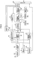
- Fig.1 is a block diagram of a voice coder by the present invention.
- voice signals are input from an input terminal 100, voice signals of one frame (20ms, for example) are stored in a buffer memory 110.
- An LPC analyzer 130 performs well-known LPC analysis from one frame voice signal, and calculates LSP parameters representing spectral characteristics of voice signals for a pre-set number of orders.
- LSP parameter coding a transforming method of LSP parameter and linear prediction coefficient to the paper titled "Quantizer design in LSP speech analysis-synthesis" (IEEE J. Sel. Areas Common., PP.432-440, 1988) by Sugamura et al. (reference No.4 ) and so on.
- vector to scaler quantization or other well-known vector quantizing methods for more efficiently quantizing LSP parameters.
- vector to scaler quantization of LS it is possible to refer to the paper titled "Transform Coding of Speech using a Weighted Vector Quantizer” (IEEE J. Sel. Areas, Commun., pp.425-431, 1988) by Moriya et al. (reference No.5) and so on.
- a subtracter 190 subtracts an output wave x(n) of the synthesis filter 281 from the voice signal x(n), and outputs a signal x'(n).
- an adaptive code vector ⁇ ⁇ v(n-M)*h(n) is calculated.
- the subtracter 195 subtracts the adaptive code vector from the signal x'(n), outputs a signal x z (n).
- x z ( n ) x '( n )- ⁇ • v ( n - M )* h ( n )
- x z (n) is an error signal
- x'(n) is an output signal of the subtracter 190
- v(n) is a past synthesis filter driving signal
- h(n) is an impulse response of the synthesis filter calculated from linear prediction coefficients.
- bl i , bh i respectively show lower limit frequency and upper limit frequency of i-th critical band.
- R shows number of critical bands included in a voice signal band.
- a masking threshold value C(i) in each critical band is calculated using the values of the equation (4), and output.
- an excitation codebook searching circuit 230 selects an excitation code vector so as to minimize the following equation (7).
- a multiplexer 260 combines output coded strings of the LSP quantizer 140, the adaptive codebook 210 and the excitation codebook searching circuit 230, and outputs a result.
- a band dividing circuit 300 for subbanding in advance input voices is further provided to the first embodiment.
- the number of divisions is supposed as two and a method using QMF filter is used for the dividing method. Under these conditions, signals of lower frequency and those of higher frequency are output.
- the frequency band width of input voice be fw(Hz)
- a switch 310 is pushed over when processing lower band signals and pulled down when processing higher band signals.
- auditory sense weighting filter coefficients are calculated in the same manner as the first embodiment, performed auditory sense weighting, and searching of an excitation codebook is conducted.
- the third embodiment further comprises a bit allocation section for allocating quantization bits to voice signals in subbanded bands in addition to the second embodiment.
- Fig.3 is a block diagram showing the third embodiment.
- a component referred with the same number as that of Fig.1 and Fig.2 is omitted to be explained because is operates similarly in Fig.1 and Fig.2.
- a masking threshold value calculator 360 calculates masking threshold values in all bands for signals that are not subbanded yet, and allocates them to the lower band or the higher band. Then, the masking threshold value calculator 360 calculates auditory sense weighting filter coefficients for the lower band or the higher band in the same manner as the first embodiment, and outputs them to the auditory sense weighting circuit 220.
- bit allocation calculator 340 uses outputs of the masking threshold value calculator 360 to allocate a number of quantization bit in the lower band and the higher band, outputs results to a codebook switching circuit 350.
- bit allocation methods there are some methods, for example, a method using a power ratio of a subbanded lower band signal and a subbanded higher band signal, or a method using a ratio of a lower band mean or minimum masking threshold value and a higher band mean or maximum masking threshold value when calculating masking threshold values in the masking threshold value calculator 360.
- the codebook switching circuit 350 inputs a number of quantization bits from the allocation circuit 340, and inputs lower band information and higher band information from the switch 320-2, and switches excitation codebooks and gain codebooks.
- the codebook can be a random numbers codebook having predetermined stochastic characteristics.
- bit allocation it is possible to use another well-known method such as a method using a power ratio of the lower band and the higher band.
- a multi-pulse calculator 3000 for calculating multi-pulses is provided, instead of the excitation codebook searching circuit 230.
- g j is j-th multi-pulse amplitude
- m j is j-th multi-pulse location
- k is a number of multi-pulses.
- the output signal of the adaptive codebook is input to the subtracter 195 in the same manner as the first embodiment and used for searching of the excitation codebook.
- critical band analysis filters in the above-mentioned embodiments can be substituted by the other well-known filters operating equivalently to the critical band analysis filters.
- calculation methods for the masking threshold values can be substituted by the other well-known methods.
- the explanation of the above embodiment is of a 1-stage excitation codebook.
- the excitation codebook could also be multi-staged, for example, 2-staged. This kind of codebook could reduce complexity of computations required for searching.
- the adaptive codebook was given as primary, but sound quality can be improved to secondary or higher degrees or by using decimal value instead of integer as delay values.
- the paper titled, "Pitch predictors with high temporal resolution” Proc. ICASSP, pp.661-664, 1990
- P. Kroon et al. Reference No.15
- LSP parameters are coded as the spectrum parameters and analyzed by LPC analysis, but other common parameters, for example, LPC cepstrum, cepstrum, improved cepstrum, generalized cepstrum, melcepstrum or the like can also be used for the spectrum parameters.
- the optimal analysis method can be used for each parameter.
- vector quantization can be conducted after nonlinear conversion is conducted on LSP parameters to account for auditory sense characteristics.
- a known example of nonlinear conversion is Mel conversion.
- LPC coefficients calculated from frames may be interpolated for each subframe in relation to LSP or in relation to linear predictive coefficients and use the interpolated coefficients in searches of the adaptive codebook and the excitation codebook. Sound quality can be further improved with this type of configuration.
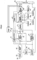
- Fig.6 is a block diagram showing the sixth embodiment. Here, for simplicity, an example of allocating number of bits of codebooks based on masking threshold values at searching excitation codebooks is shown. However, it can be applied for adaptive codebooks and other types of codebooks.
- voice signals are input from an input terminal 600 and one frame of voice signals (20 ms, for example) is stored in a buffer memory 610.
- An LPC analyzer 630 conducts well-known LPC analysis from voice signals of said frames and calculates LPC parameters that represent spectral characteristics of framed voice signals for a preset number of letters L.
- an LSP quantization circuit 640 quantizes the LSP parameters in a preset number of quantization bit and outputs the obtained code lk to a multiplexer 790.
- an impulse response circuit 670 and a synthetic filter 795 For coding method of LSP parameters and transformation of LSP parameters and linear prediction coefficients, it is possible to refer to the above-mentioned Reference No.4, etc.
- vector-scaler quantization or other well-known vector quantization methods can be used for more efficient quantization of LSP parameters.
- the above-mentioned Reference No.5, etc. can be referred to.
- a subframe dividing circuit 650 divides framed voice signals into subframes.
- subframe length is supposed as 5 ms.
- An impulse response calculating circuit 670 calculates impulse response h wm (n) of a filter having transfer characteristics of Equation (22) in a preset length, and outputs a result.
- a w ( z ) H wm ( z )•[1/ A ( z )]
- An adaptive codebook 710 inputs the weighted impulse response h wn (n) from the impulse response calculating circuit 670, a weighted signal from the subtracter 690, respectively. Then, it performs pitch prediction based on long-term correlation, calculates delay M and gain ⁇ as pitch parameters.
- a bit allocating circuit 715 inputs a masking threshold value spectrum T i , T' i or T'' i . Then, it performs bit allocation according to the Equation (25) or the Equation (26).
- bit allocation information is output to the multiplexer 790.
- the gain codebook searching circuit 760 searches and outputs a gain code vector that minimizes the following equation using a selected excitation code vector and the gain codebook 770.
- indexes of the selected adaptive code vector, the excitation code vector and the gain code vector are output.
- a subbanding circuit 800 divides voice signals into a preset number of bands, w, for example.
- k and j of R kj represent j-th subframe and k-th band, respectively.
- j 1...L
- k 1...W.
- Fig.8 is a block diagram showing configurations of the voice coding circuits 900 1 to 900 w .
- the auditory sense weighting circuit 720 inputs the filter coefficient b i for performing auditory sense weighting, operates in the same manner as the auditory sense weighting circuit 720 in Fig.7.
- the excitation codebook searching circuit 730 inputs the bit allocation value R kj for each band, and switches number of bits of excitation codebooks.
- the excitation codebook searching circuit 1030 inputs bit allocation values for each subframe and band from the bit allocating circuit 920, and switches excitation codebooks for each band and subframe according to the bit allocation values. It has N kinds of codebooks of which number of bits are different, for respective bands. For example, the band 1 has codebooks 1000 11 to 1000 1N .
- bit allocation method for deciding bit allocation method, it is possible a method of clustering SMR in advance, designing codebooks for bit allocation, in which SMR for each cluster and allocation number of bits are configured in a table, for a preset bit number (B bits, for example), and using these codebooks for calculating bit allocation in the bit allocating circuit.
- codebooks for bit allocation in which SMR for each cluster and allocation number of bits are configured in a table, for a preset bit number (B bits, for example), and using these codebooks for calculating bit allocation in the bit allocating circuit.
- Equation (33) can be used for bit allocation for each subframe and band.
- Q k is a number of critical bands included in k-th subband.
- bit allocating method in the bit allocating circuits 715 and 920, it it possible to allocate a number of bits once, perform quantization using excitation codebooks by the allocated number of bits, measure quantization noises and adjust bit allocation so that Equation (34) is maximized.
- ⁇ nj 2 is a quantization noise measured by using j-th subframe.
- Fig .10 is a block diagram showing the ninth embodiment. Explanation for a component in Fig.10 referred by the same number as that in Fig.7 is omitted, because it operates similarly to that of Fig.7.
- a multipluse calculating circuit 1100 for calculating multipulses is provided instead of the excitation codebook searching circuit 730.
Description
- The present invention relates to voice coding technics for encoding voice signals in high quality at low bit rates, especially at 8 to 4.8 kb/s.
- As a method for coding voice signals at low bit rates of about 8 to 4.8 kb/s, for example, there is CELP (Code Excited LPC Coding ) method described in the paper titled "Code-excited linear prediction: High quality speech at very low bit rates" (Proc. ICASSP, pp.937-940, 1985) by M. Sahroeder and B. Atal (reference No.1) and the paper titled "Improved speech quality and efficient vector quantization in SELP " (ICASSP, pp.155-158, 1988) by Kleijn et al. (reference No.2).
- In the method described in these papers, spectral parameters representing spectral characteristics of voice signals are extracted in the transmission side from voice signals for each frame (20ms, for example). Then, the frames are divided into subframes (5ms, for example), and pitch parameters of an adaptive codebook representing long-term correlation (pitch correlation) are extracted so as to minimize a weighted squared error between a signal regenerated based on a past excitation signal for each subframe and the voice signal. Next, the subframe's voice signals are predicted in long-term based on these pitch parameters, and based on residual signals calculated through this long-term prediction, one kind of noise signals is selected so as to minimize weighted squared error between a signal synthesized from signals selected from a codebook consisting of pre-set kinds of noise signals and the voice signal, and an optimal gain is calculated. Then, an index representing a type of the selected noise signal, gain, the spectral parameter and the pitch parameters are transmitted.
- In addition, as another method for coding voice signals at low bit rates of about 8 to 4.8 kb/s, the multi-pulse coding method described in the paper titled "A new model of LPC excitation for producing natural-sounding speech at low bit rates" (Proc. ICASSP, pp.614-617, 1982) by B. Atal et al. (reference No.3) etc. is known.
- In the method of reference No.3, the residual signal of above-mentioned method is represented by a multi-pulse consisting of a pre-set number of pulse strings of which amplitude and locations are different from others, amplitude and location of the multi-pulse are calculated. Then, amplitude and location of the multi-pulse, the spectral parameter and the pitch parameters are transmitted.
- In the prior art described in references No.1, No.2 and No.3, as an error evaluation criterion, a weighted squared error between a supplied voice signal and a regenerated signal from the codebook or the multi-pulse is used when searching a codebook consisting of multi-pulses, adaptive codebook and noise signals.
- The following equation shows such a weighted scale criterion.

- Where, w(z) represents transfer characteristics of a weighting filter, ai is a linear prediction coefficient calculated from a spectral parameter. γ1 i, γ2 i are constants for controlling weighting quantity, they are set in 0<γ2<γ1<1, usually.
- However, there is a problem that speech quality of regenerated voices using code vectors selected with this criterion or calculated multi-pulses do not always fit to natural auditory feeling because this evaluation criterion does not match with natural auditory feeling.
- Moreover, this problem becomes particularly noticeable when bit rate was reduced and the codebook was reduced in size.
- Furthermore, in the above-mentioned prior art, the number of bits of codebook in each subframe is supposed constant when searchino a codebook consisting of noise signals. Additionally, the number of multipulses in a frame or a subframe is also constant when calculating a multipulse.
- However, power of voice signals remarkably varies as time passes, so it has been difficult to code voices in high quality by a method using constant number of bits where power of voice signals varies as time passes. Especially, this problem becomes serious under the conditions that bit rates are reduced and sizes of codebooks are minimized.
- It is an object of the present invention to solve the above-mentioned problems.
- Another object of the present invention is to provide a voice coding art matching auditory feeling.
- Moreover, another object of the present invention is to provide a voice coding art enabling to reduce bit rates than prior art.
- These objects are achieved with a voice coder according to claims 1 and 8, and with a method according to claims 22 and 33.
- The above-mentioned objects of the present invention are achieved by a voice coder comprising a masking calculating means for calculating masking threshold values from supplied discrete voice signals based on auditory sense masking characteristics, auditory sense weighting means for calculating filter coefficients based on the masking threshold values and weighting input signals based on the filter coefficients, a plurality of codebooks, each of them consisting of a plurality of code vectors, and a searching means for searching a code vector that minimizes output signal power of the auditory sense weighting means from the codebooks.
- The voice coder of the present invention performs, for each of subframes created by dividing frames, auditory sense weighting calculated based on auditory sense masking characteristics to signals supplied to adaptive codebooks, excitation codebooks or multi-pulse when searching adaptive codebooks and excitation codebooks or calculating multi-pulses.
- In auditory sense weighting, masking threshold values are calculated based on auditory sense masking characteristics, an error scale is calculated by performing auditory sense weighting to supplied signals based on the masking threshold values. Then, an optimal code vector is calculated from the codebooks so as to minimize the error scale. Namely, a code vector that minimizes weighted error power as shown in the following equation.

- This and other objects, features and advantages of the present invention will become more apparent upon a reading of the following detailed description and drawings.
- Fig.1 is a block diagram showing the first embodiment of the present invention.
- Fig.2 is a block diagram showing the second embodiment of the present invention.
- Fig.3 is a block diagram showing the third embodiment of the present invention.
- Fig.4 is a block diagram showing the fourth embodiment of the present invention.
- Fig.5 is a block diagram showing the fifth embodiment of the present invention.
- Fig.6 is a block diagram showing the sixth embodiment.
- Fig.7 is a block diagram showing the seventh embodiment.
- Fig.8 is a block diagram showing the seventh embodiment.
- Fig.9 is a block diagram showing the eighth embodiment.
- Fig.10 is a block diagram showing the ninth embodiment.
- First, the first embodiment of the present invention is explained.
- In this first embodiment, an error signal output from an auditory sense weighting filter based on masking threshold values is used for searching an excitation codebook.
- Fig.1 is a block diagram of a voice coder by the present invention.
- In the transmission side of Fig.1, voice signals are input from an
input terminal 100, voice signals of one frame (20ms, for example) are stored in abuffer memory 110. AnLPC analyzer 130 performs well-known LPC analysis from one frame voice signal, and calculates LSP parameters representing spectral characteristics of voice signals for a pre-set number of orders. - Next, an
LSP quantization circuit 140 outputs a code lk obtained by quantizing LSP parameters with a pre-set quantization bit number to amultiplexer 260. Then, it decodes the code lk, transforms it linear prediction coefficient ai' (i=1 to L ), and outputs a result to animpulse response calculator 170 and asynthesis filter 281. - It is to be noted that it is possible to refer on LSP parameter coding, a transforming method of LSP parameter and linear prediction coefficient to the paper titled "Quantizer design in LSP speech analysis-synthesis" (IEEE J. Sel. Areas Common., PP.432-440, 1988) by Sugamura et al. (reference No.4 ) and so on. Also, it is possible to use vector to scaler quantization or other well-known vector quantizing methods for more efficiently quantizing LSP parameters. On vector to scaler quantization of LS?, it is possible to refer to the paper titled "Transform Coding of Speech using a Weighted Vector Quantizer" (IEEE J. Sel. Areas, Commun., pp.425-431, 1988) by Moriya et al. (reference No.5) and so on.
- A subframe dividing
circuit 150 divides one frame voice signal into subframes. As an example, the subframe length is supposed as 5 ms. - A
subtracter 190 subtracts an output wave x(n) of thesynthesis filter 281 from the voice signal x(n), and outputs a signal x'(n). - The
adaptive codebook 210 inputs an input signal v(n) of thesynthesis filter 281 through adelay circuit 206, and inputs a weighted impulse response h(n) from an impulseresponse output circuit 170 and the signal x' (n) from thesubtracter 190. Then, it performs long-term correlation pitch prediction based on these signals and calculates delay M and gain β as pitch parameters. - Here, adaptive codebook prediction order is supposed as 1. However, the value can be 2 or more. Moreover, the papers (references No.1, 2) and so on can be referred to on calculation of delay M in the adaptive codebook.
- Next, using the calculated gain β, an adaptive code vector β · v(n-M)*h(n) is calculated. Then, the
subtracter 195 subtracts the adaptive code vector from the signal x'(n), outputs a signal xz(n). - Where, xz(n) is an error signal, x'(n) is an output signal of the
subtracter 190, v(n) is a past synthesis filter driving signal, h(n) is an impulse response of the synthesis filter calculated from linear prediction coefficients. - A masking
threshold value calculator 205 calculates a spectrum X(k)(k=0 to N-1) by FFT transforming the voice signal x(n) at N points, next calculates a power spectrum |X(k)|2, and calculates power or RMS for each critical band by analyzing the result using a critical band filter or a auditory sense model. The following equation is used for power calculation.
- Where, bli, bhi respectively show lower limit frequency and upper limit frequency of i-th critical band. R shows number of critical bands included in a voice signal band.
- Next, a masking threshold value C(i) in each critical band is calculated using the values of the equation (4), and output.
- Here, as a method of calculating masking threshold values, for example, a method using values obtained through auditory sense psychological experiments is known. It is possible to refer in details to the paper titled "Transform coding of audio signals using perceptual noise criteria" (IEEE J. Sel. Areas on Commun., pp.314-323, 1988) by Johnston et al. (reference No.6) or the paper titled "Vector quantization and perceptual criteria in SVD based CELP coders" (ICASSP, pp.33-36, 1990) by R. Drogo de lacovo et al. (reference No.7).
- Moreover, for critical band filters or critical band analysis, for example, it is possible to refer to the fifth chapter (reference No.8) of the book titled "Foundation of modern auditory theory" and so on by J. Tobias. In addition, for auditory models, for example, it is possible to refer to the paper titled "A computational model for the peripheral auditory system: Application to speech recognition research" (Proc. ICASSP, pp.1983-1986, 1986) by Seneff (reference No. 9) and so on.
- Next, each masking threshold value c(i) is transformed to power to obtain power spectrum, and auto-correlation function r(j)(j=0 · · · N-1) is calculated through inverse FFT operation.
- Then, a filter coefficient bi (i=1 · · · P ) is calculated by operating well-known linear prediction analysis to P+1 auto-correlation functions.
- The auditory
sense weighting circuit 220 operates weighting, according to the following equation, to the error signal xz(n) obtained by the equation (3) in theadaptive codebook 210, using the filter coefficient bi, and a weighted signal xzm(n) is obtained. - Where, Wm(n) is an impulse response of an auditory sense weighting filter consisting of the filter coefficient bi.
- Here, for the auditory sense weighting filter, a filter having a transfer function represented by the following equation (6) can be used.

- Where, γ2 and γ1 are constants meeting 0≦γ2<γ1≦1.
- Next, an excitation
codebook searching circuit 230 selects an excitation code vector so as to minimize the following equation (7).
- Where, γj is an optimal gain to the code vector cj(n)(j=0 · · · · 2B-1, where B is a number of bits of an excitation codebook).
- It is to be noted that the
excitation codebook 235 is made in advance through training. For example, for the codebook design method by training, it is possible to refer to the paper titled "An Algorithm for Vector Quantization Design" (IEEE Trans. COM-28, pp.84-95, 1980) by Linde et al. (reference No.10) and so on. - A
gain quantization circuit 282 quantizes gains of theadaptive codebook 210 and theexcitation codebook 235 using thegain codebook 285. - An
adder 290 adds an adaptive code vector of theadaptive codebook 210 and an excitation code vector of the excitationcodebook searching circuit 230 as below, and outputs a result. - A
synthesis filter 281 inputs an output v(n) of theadder 290, calculates synthesized voices for one frame according to the following equation, in addition, inputs 0 string to the filter for another one frame to calculate a response signal string, and outputs a response signal string for one frame to thesubtracter 190.

- A
multiplexer 260 combines output coded strings of theLSP quantizer 140, theadaptive codebook 210 and the excitationcodebook searching circuit 230, and outputs a result. - This is the explanation of the first embodiment.
- Next, the second embodiment is explained.
- Fig.2 is a block diagram showing the second embodiment. In Fig.2, a component referred with the same number as that in Fig.1 operates similarly in Fig.1, so explanations for it is omitted.
- In the second embodiment, a
band dividing circuit 300 for subbanding in advance input voices is further provided to the first embodiment. Here, for simplicity, the number of divisions is supposed as two and a method using QMF filter is used for the dividing method. Under these conditions, signals of lower frequency and those of higher frequency are output. - For example, if letting the frequency band width of input voice be fw(Hz), it is possible to divide a band as 0 to fw/2 for the lower band and fw/2 to fw for the higher band.
- Then, a
switch 310 is pushed over when processing lower band signals and pulled down when processing higher band signals. - It is to be noted that, as a method for subbanding using QMF filters, for example, it is possible to refer to the book titled "Multirate Signal Processing" (Prentice-Hall, 1983) by Crochiere et al. (reference No.11) and so on. In addition, as other methods, it is possible to consider a method for operating FFT to signals and performing frequency dividing on FFT, then operating inverse FFT.
- Here, to a voice signal in each band that is subbanded, auditory sense weighting filter coefficients are calculated in the same manner as the first embodiment, performed auditory sense weighting, and searching of an excitation codebook is conducted.
- It is possible to prepare two kinds of excitation codebooks for the lower band and the higher band and to use them by switching.
- This is the explanation for the second embodiment of the present invention.
- Next, the third embodiment is explained.
- The third embodiment further comprises a bit allocation section for allocating quantization bits to voice signals in subbanded bands in addition to the second embodiment.
- Fig.3 is a block diagram showing the third embodiment. In this figure, a component referred with the same number as that of Fig.1 and Fig.2 is omitted to be explained because is operates similarly in Fig.1 and Fig.2.
- In Fig.3, switches 320-1 and 320-2 switch the circuit to the lower band or the higher band, and output lower band signals or higher band signals, respectively. The switch 320-2 outputs information indicating to where an output signal belongs, the lower band or the higher band, to the
codebook switching circuit 350. - A masking
threshold value calculator 360 calculates masking threshold values in all bands for signals that are not subbanded yet, and allocates them to the lower band or the higher band. Then, the maskingthreshold value calculator 360 calculates auditory sense weighting filter coefficients for the lower band or the higher band in the same manner as the first embodiment, and outputs them to the auditorysense weighting circuit 220. - Using outputs of the masking
threshold value calculator 360, abit allocation calculator 340 allocates a number of quantization bit in the lower band and the higher band, outputs results to acodebook switching circuit 350. As bit allocation methods, there are some methods, for example, a method using a power ratio of a subbanded lower band signal and a subbanded higher band signal, or a method using a ratio of a lower band mean or minimum masking threshold value and a higher band mean or maximum masking threshold value when calculating masking threshold values in the maskingthreshold value calculator 360. - The
codebook switching circuit 350 inputs a number of quantization bits from theallocation circuit 340, and inputs lower band information and higher band information from the switch 320-2, and switches excitation codebooks and gain codebooks. Here, it is possible to prepare in advance the codebooks by using training data, or the codebook can be a random numbers codebook having predetermined stochastic characteristics. - Here, for bit allocation, it is possible to use another well-known method such as a method using a power ratio of the lower band and the higher band.
- The above is the explanation for the third embodiment of the present invention.
- Next, the fourth embodiment is explained.
- In the fourth embodiment, a
multi-pulse calculator 3000 for calculating multi-pulses is provided, instead of the excitationcodebook searching circuit 230. - Fig.4 is a block diagram of the fourth embodiment. In Fig.4, a component referred with the same number as that of Fig.1 is omitted to be explained, because it operates similarly in Fig.1.
- The
multi-pulse calculator 3000 calculates amplitude and location of a multi-pulse that minimizes the following equation.
- Where, gj is j-th multi-pulse amplitude, mj is j-th multi-pulse location, k is a number of multi-pulses.
- The above is all of explanations for the fourth embodiment of the present invention.
- Next, the fifth embodiment is explained.
- The fifth embodiment is a case of providing the auditory
sense weighting circuit 220 of the first embodiment ahead of theadaptive codebook 210 as shown in Fig.5 and searching an adaptive code vector with an auditory sense weighted signal. In addition, auditory sense weighting is conducted before searching of an adaptive code vector in the fifth embodiment, all searching after this step, for example, searching of the excitation codebook is also conducted with an auditory sense weighted signal. - Input voice signals are weighted in the auditory
sense weighting circuit 220 in the same manner as that in the first embodiment. The weighted signals are subtracted by outputs of the synthesis filter in thesubtracter 190, input to theadaptive codebook 210. - The
adaptive codebook 210 calculates delay M and gain β of the adaptive codebook that minimizes the following equation.
- Where, x'wm(n) is an output signal of the
subtracter 190, hwm(n) is an output signal of the impulseresponse calculating circuit 170. - Then, the output signal of the adaptive codebook is input to the
subtracter 195 in the same manner as the first embodiment and used for searching of the excitation codebook. - The above is the explanation of the fifth embodiment of the present invention.
- It is to be noted that the critical band analysis filters in the above-mentioned embodiments can be substituted by the other well-known filters operating equivalently to the critical band analysis filters.
- Also, the calculation methods for the masking threshold values can be substituted by the other well-known methods.
- Furthermore, the excitation codebook can be substituted by the other well-known configurations. For the configuration of the excitation codebook, it is possible to refer to the paper titled "On reducing computational complexity of codebook search in CELP coder through the use of algebraic codes" (Proc. ICASSP, pp.177-180, 1990) by C. Laflamme et al. (reference No.12) and the paper titled "CELP: A candidate for GSM half-rate coding" (Proc. ICASSP, pp.469-472, 1990) by I. Trancoso et al. (reference No.13).
- Furthermore, the more effective codebooks by matrix quantization, finite vector quantization, trellis quantization, delayed decision quantization and so on are used, the better characteristics can be obtained. For more detailed information, it is possible to refer to the paper titled "Vector quantization" (IEEE ASSP Magazine, pp.4-29, 1984) by Gray (reference No.14) and so on.
- The explanation of the above embodiment is of a 1-stage excitation codebook. However, the excitation codebook could also be multi-staged, for example, 2-staged. This kind of codebook could reduce complexity of computations required for searching.
- Also, the adaptive codebook was given as primary, but sound quality can be improved to secondary or higher degrees or by using decimal value instead of integer as delay values. For details, the paper titled, "Pitch predictors with high temporal resolution" (Proc. ICASSP, pp.661-664, 1990) by P. Kroon et al. (Reference No.15), and so on can be referred to.
- In the above embodiment, LSP parameters are coded as the spectrum parameters and analyzed by LPC analysis, but other common parameters, for example, LPC cepstrum, cepstrum, improved cepstrum, generalized cepstrum, melcepstrum or the like can also be used for the spectrum parameters.
- Also, the optimal analysis method can be used for each parameter.
- In vector quantization of LSP parameters, vector quantization can be conducted after nonlinear conversion is conducted on LSP parameters to account for auditory sense characteristics. A known example of nonlinear conversion is Mel conversion.
- It is also possible to have a configuration by which LPC coefficients calculated from frames may be interpolated for each subframe in relation to LSP or in relation to linear predictive coefficients and use the interpolated coefficients in searches of the adaptive codebook and the excitation codebook. Sound quality can be further improved with this type of configuration.
- Auditory sense weighting based on the masking threshold values indicated in the embodiments can be used for quantization of gain codebook, spectral parameters and LSP.
- Also, when determining auditory sense weighting filters, it is possible to use masking threshold values from simultaneous masking together with masking threshold values from successive masking.
- Furthermore, instead of determining auditory sense weighting coefficients directly from masking threshold values, it is possible to multiply masking threshold values by weighting coefficients and then convert the results to auditory sense weighting filter coefficients.
- Other common configurations for auditory sense weighting filter can also be used.
- Next, the sixth embodiment is explained.
- Fig.6 is a block diagram showing the sixth embodiment. Here, for simplicity, an example of allocating number of bits of codebooks based on masking threshold values at searching excitation codebooks is shown. However, it can be applied for adaptive codebooks and other types of codebooks.
- In Fig.6, at transmitting side, voice signals are input from an
input terminal 600 and one frame of voice signals (20 ms, for example) is stored in abuffer memory 610. - An
LPC analyzer 630 conducts well-known LPC analysis from voice signals of said frames and calculates LPC parameters that represent spectral characteristics of framed voice signals for a preset number of letters L. - Then, an
LSP quantization circuit 640 quantizes the LSP parameters in a preset number of quantization bit and outputs the obtained code lk to amultiplexer 790. The code is decoded and transformed to the linear prediction coefficient ai' (i=1 to P) and output to animpulse response circuit 670 and asynthetic filter 795. For coding method of LSP parameters and transformation of LSP parameters and linear prediction coefficients, it is possible to refer to the above-mentioned Reference No.4, etc. In addition, for more efficient quantization of LSP parameters, vector-scaler quantization or other well-known vector quantization methods can be used. For LSP vector-scaler quantization, the above-mentioned Reference No.5, etc. can be referred to. - A
subframe dividing circuit 650 divides framed voice signals into subframes. Here, for example, subframe length is supposed as 5 ms. - A masking threshold
value calculating circuit 705 performs FFT transformation to an input signal x(n) of N points and calculates a spectrum x(k) (where, k=0 to N-1). Continuously, it calculates power spectrum |X(k)|2, analyzes the result by using critical filter models or auditory sense models and calculates power of each critical band or RMS. Here, for calculations of power, the following equation is used.
- Here, bli and bhi are lower limit frequency and upper limit frequency of i-th critical band, respectively. R represents a number of critical bands included in a voice signal band. About the critical band, the above-mentioned Reference No.8 can be referred to.
- Then, spreading functions are convoluted in a critical band spectrum according to the following equation.

- Here, sprd(j, i) is a spreading function and Reference No.6 can be referred to for its specific values. bmax is a number of critical bands included from 0 to π in each frequency.
- Next, masking threshold value spectrum Thi is calculated using the following equation.
- Where,

- Here, ki is an i-th k parameter, and it is calculated by transforming a linear prediction coefficient input from the
LPC analyzer 630 using a well-known method. M is a number of order of linear prediction analysis. - Considering absolute threshold values, a masking threshold value spectrum is represented as below.
- Where, absthi is an absolute threshold value in an i-th critical band, it can be referred to Reference No.7.
- Next, transforming the frequency axis from the bulk axis to the Hz axis, a power spectrum Pm(f) to masking threshold value spectrum T · i (i=1...bmax) is obtained. By performing inverse FFT, auto-correlation function r(j) (j=0...N-1) can be calculated.
- Continuously, by performing a well-known linear prediction analysis to the auto-correlation function, a filter coefficient bi(i=1...P) is calculated.
- The auditory
sense weighting circuit 720 conducts auditory sense weighting - Using the filter coefficient bi, the auditory
sense weighting circuit 720 performs filtering of supplied voice signals with a filter having the transfer characteristics specified by Equation (21), then performs auditory sense weighting to the voice signals and outputs a weighted signal Xwm(n).
- Where, γ1 and γ2 are constants for controlling weighting quantity, they usually meets 0≦γ2<γ1≦1.
- An impulse
response calculating circuit 670 calculates impulse response hwm(n) of a filter having transfer characteristics of Equation (22) in a preset length, and outputs a result. - Where,and ai' is output from the

LSP quantization circuit 640. - A
subtracter 690 subtracts the output of thesynthetic filter 795 from a weighted signal and outputs a result. - An
adaptive codebook 710 inputs the weighted impulse response hwn(n) from the impulseresponse calculating circuit 670, a weighted signal from thesubtracter 690, respectively. Then, it performs pitch prediction based on long-term correlation, calculates delay M and gain β as pitch parameters. - In the following explanations, the prediction order of the adaptive codebook is supposed as 1, however it can be supposed as 2 or more. For calculations of delay M in an adaptive codebook can be referred to the above-mentioned Reference No.1 and No.2.
- Successively, gain β is calculated and an adaptive code vector xz(n) is calculated, according to the following equation, to be subtracted from the output of
subtracter 690. - Where, xwm(n) is an output signal of the
subtracter 690, v(n) is a past synthetic filter driving signal. hwm (n) is output from the impulseresponse calculating circuit 670. The symbol * represents convolution integration. - A
bit allocating circuit 715 inputs a masking threshold value spectrum Ti, T'i or T''i. Then, it performs bit allocation according to the Equation (25) or the Equation (26).

- Where, to set the number of bits of whole frame to a preset value as shown by the Equation (27), the number of bits is adjusted so that the allocated number of bits of subframes is in the range from the lower limit number of bits to the upper limit number of bits.

- Where, Rj, RT, Rmin, Rmax represent the allocated number of bits of j-th subframe, the total number of bits of whole frames, the lower limit number of bits of a subframe and the upper limit number of bits of the subframe, respectively. L represents a number of subframes in a frame.
- As a result of the above processings, bit allocation information is output to the
multiplexer 790. - The excitation
codebook searching circuit 730 having codebooks 7501 to 750N of which numbers of bits are different from others inputs allocated numbers of bits of respective subframes and switches the codebooks (7501 to 750N) according to the number of bits. And it selects an excitation code vector that minimizes the following equation.
- Where, γk is an optimal gain to a code vector ck(n) (j=0...2B-1, where B is the number of bits of excitation codebook). The hwm(n) is an impulse response calculated with the
impulse response calculator 670. - It is possible, for example, to prepare the excitation codebook using Gaussian random number as shown in Reference No.1, or by training in advance. For the codebook configuration method by training, for example, it is possible to refer to the paper titled "An Algorithm for Vector Quantization Design" (IEEE Trans. COM-28, pp.84-95, 1980) by Linde et al.
- The gain
codebook searching circuit 760 searches and outputs a gain code vector that minimizes the following equation using a selected excitation code vector and thegain codebook 770.
- Where, g1k, g2k are k-th quadratic gain code vectors.
- Next, indexes of the selected adaptive code vector, the excitation code vector and the gain code vector are output.
- The
multiplexer 790 combines the outputs of theLSP quantization circuit 640, thebit allocating circuit 715 and the gaincodebook searching circuit 760 and outputs a result. - The
synthetic filter circuit 795 calculates weighted regeneration signal using an output of the gaincodebook searching circuit 760, and outputs a result to thesubtracter 690. - The above is the explanation of the sixth embodiment.
- Next, the seventh embodiment is explained.
- Fig.7 is a block diagram showing the seventh embodiment.
- Explanation for a component in Fig.7 referred by the same number as that in Fig.6 is omitted, because it operates similarly to that of Fig.6.
- A
subbanding circuit 800 divides voice signals into a preset number of bands, w, for example. - The band width of each band is set in advance. QMF filter banks are used for subbanding. For configurations of the QMF filter banks, it is possible to refer to the paper titled "Multirate digital filters, filter banks, polyphase networks, and applications: A tutorial" (Proc. IEEE, pp.56-93, 1990) by P.Vaidyanathan et al. (Reference No.16).
- The masking threshold
value calculating circuit 910 calculates masking threshold values of each critical band similarly to the masking thresholdvalue calculating circuit 705. Then, according to the Equation (30), it calculates SMRkj using masking threshold values included in each band subbanded with thesubbanding circuit 800, and outputs a result to thebit allocating circuit 920. - In addition, it calculates filter coefficient bi from masking threshold values included in each band in the same manner as that in the masking threshold
value calculating circuit 705 of Fig.6, outputs a result to the voice coding circuits 9001 to 900w. - According to the Equation (31), the
bit allocating circuit 920 allocates a number of bits to each subframe and band using SMRkj(j=1...L, k=1...W) supplied by the masking thresholdvalue calculating circuit 910, outputs a result to the voice coding circuits 9001 to 900w.
- Where, k and j of Rkj represent j-th subframe and k-th band, respectively. Here, j=1...L, k=1...W.
- Fig.8 is a block diagram showing configurations of the voice coding circuits 9001 to 900w.
- Only the configuration of the voice coding circuit 9001 of the first band is shown in Fig.8, because all of the voice coding circuits 9001 to 900w operate similarly each other. Explanation for a component in Fig.8 referred by the same number as that in Fig.7 is omitted, because it operates similarly to that of Fig.7.
- The auditory
sense weighting circuit 720 inputs the filter coefficient bi for performing auditory sense weighting, operates in the same manner as the auditorysense weighting circuit 720 in Fig.7. - The excitation
codebook searching circuit 730 inputs the bit allocation value Rkj for each band, and switches number of bits of excitation codebooks. - This is explanation for the seventh embodiment.
- Next, the eighth embodiment is explained.
- Fig .9 is a block diagram showing the eighth embodiment. Explanation for a component in Fig.9 referred by the same number as that in Fig.7 or Fig.8 is omitted, because it operates similarly to that of Fig.7 or Fig.8.
- The excitation
codebook searching circuit 1030 inputs bit allocation values for each subframe and band from thebit allocating circuit 920, and switches excitation codebooks for each band and subframe according to the bit allocation values. It has N kinds of codebooks of which number of bits are different, for respective bands. For example, the band 1 has codebooks 100011 to 10001N. - In addition, for each band, impulse responses of concerned subbanding filters are convoluted in all code vectors of a codebook. In the band 1, for example, impulse responses of the subbanding filter for the band 1 are calculated using Reference No.16, they are convoluted in advance in all code vectors of N codebooks of band 1.
- Next, bit allocation values for respective bands are input for respective subframes, a codebook according to the number of bits is read out, code vectors for all bands (w, for this example) are added and a new code vector c(n) is created according to the following Equation (32).

- Then, a code vector that minimizes the Equation (28) is selected.
- If searching is done for all possible combinations for all bands of a codebook of each band, tremendous computational operations are needed. Therefore, it is possible to adopt a method of subbanding output signals of adaptive codebooks, selecting a plurality of candidates of code vectors of which distortion is small from concerned codebooks for each band, restoring codebooks of all bands using Equation (32) for each combination of the candidates in all bands, and selecting a code vector that minimizes distortion from all combinations. With this method, computational complexity for searching code vectors can be remarkably reduced.
- In the above embodiment, for deciding bit allocation method, it is possible a method of clustering SMR in advance, designing codebooks for bit allocation, in which SMR for each cluster and allocation number of bits are configured in a table, for a preset bit number (B bits, for example), and using these codebooks for calculating bit allocation in the bit allocating circuit. With this configuration, transmission information for bit allocation can be reduced because bit allocation information to be transmitted is enough B bits for a frame.
- Moreover, in the seventh and eighth embodiments, Equation (33) can be used for bit allocation for each subframe and band.

- Where, Qk is a number of critical bands included in k-th subband.
- It is to be noted that, in the above embodiments, examples of adaptively allocating numbers of bits of excitation codebooks are shown, however, the present invention can be applied to bit allocation for LSP codebooks, adaptive codebooks and gain codebooks as well as excitation codebooks.
- Furthermore, as a bit allocating method in the
bit allocating circuits 
- Where, σnj 2 is a quantization noise measured by using j-th subframe.
- Moreover, as a method for calculating of the masking threshold value spectrum, other well-known methods can be used.
- Next, the ninth embodiment is explained.
- Fig .10 is a block diagram showing the ninth embodiment. Explanation for a component in Fig.10 referred by the same number as that in Fig.7 is omitted, because it operates similarly to that of Fig.7.
- In the ninth embodiment, a
multipluse calculating circuit 1100 for calculating multipulses is provided instead of the excitationcodebook searching circuit 730. - The
multipluse calculating circuit 1100 calculates amplitude and location of a multipulse based on the Equation (1) in the same manner as the embodiment 4. But, a number of multipulses is dependent on the number of multipulses from thebit allocating circuit 715.
Claims (34)
- A voice coder comprising:a masking calculating means (205, 360, 910) for calculating masking threshold values from supplied discrete voice signals based on auditory sense masking characteristics;an auditory sense weighting means (220) for calculating filter coefficients based on said masking threshold values and weighting input signals based on said filter coefficients;a codebook (210, 235) consisting of a plurality of code vectors; anda searching means (230) for searching a code vector that minimizes output signal power of said auditory sense weighting means from said codebook.
- The voice coder of Claim 1, wherein said codebook is an excitation codebook (235).
- The voice coder of Claim 1, wherein said codebook is an adaptive codebook (210, 710).
- The voice coder of any of claims 1 to 3, comprising a subframe generating means (150) for dividing said voice signals into frames of a pre-set time length and generating subframes by dividing said frames into pre-set time length divisions, wherein searching of said codebook is performed for each said subframe.
- The voice coder of claim 1, further comprising:a dividing means (110) for dividing said supplied discrete voice signals into pre-set time length frames;a subframe generating means (150) for generating subframes by dividing said frames into pre-set time length divisions;an adaptive codebook means, being a part of said codebook, for regenerating said voice signals for said subframes based on an adaptive codebook (210, 710);said masking calculating means being for calculating masking threshold values for each of said subframes;said auditory sense weighting means being further for performing auditory sense weighting to an error signal of a signal regenerated with said adaptive codebook means and said voice signal;an excitation codebook (235), being a further part of said codebook, consisting of a plurality of code vectors; andsaid searching means being for searching a code vector that minimizes error signal power weighted with said auditory sense weighting means.
- The voice coder of claim 1, further comprising:a dividing means (110) for dividing said supplied discrete voice signals into pre-set time length frames;a subframe generating means (150) for generating subframes by dividing said frames into pre-set time length divisions;said masking calculating means being for calculating masking threshold values for each of said subframes;said auditory sense weighting means (220) further being for performing auditory sense weighting to said voice signals;an adaptive codebook means (210), being a part of said codebook, for calculating an adaptive code vector that minimizes power of a difference signal between a response signal and a voice signal weighted with said auditory sense weighting means;said codebook being an excitation codebock (235), being a further part of said codebook, consisting of a plurality of excitation code vectors; andsaid searching means being for searching a code vector that minimizes error signal power between an output signal of said adaptive codebock means and said difference signal.
- The voice coder of claim 6, wherein said adaptive codebook means (210, 710) calculates, for each of said subframes, a pitch parameter so that a signal regenerated based on an adaptive codebook consisting of past excitation signals comes close to said voice signal.
- A voice coder comprising:a dividing means (110) for dividing supplied discrete voice signals into pre-set time length frames;a subframe generating means (150) for generating subframes by dividing said frames into pre-set time length divisions;an adaptive codebook means (210) for regenerating said voice signals for each of said subframes based on an adaptive codebook;a masking calculating means (205) for calculating masking threshold values from said voice signals based on auditory sense masking characteristics;an auditory sense weighting means (220) for calculating filter coefficients based on said masking threshold values and performing auditory sense weighting to an error signal between said voice signal and a signal regenerated with said adaptive codebook means based on said filter coefficients; anda calculating means (3000) for calculating a multi-pulse that minimizes error signal power weighted with said auditory sense weighting means.
- The voice coder of any of Claims 1 to 8, further comprising a subbanding means for subbanding said voice signals, wherein said auditory sense weighting means performs weighting to a signal subbanded with said subbanding means.
- The voice coder of Claim 9, further comprising:a bit allocating means (340, 715) for allocating quantization bits to subbanded signals; anda switching means (350) for switching a number of bits of said excitation codebook according to bits allocated with said allocating means.
- The voice coder of any of claims 1 to 10, comprising a spectral parameter calculating means for calculating and outputting, for each said frames, a spectral parameter representing spectral envelope of said voice signals.
- The voice coder of claim 8, wherein
said adaptive codebook means is provided for calculating pitch parameters so as to make signals regenerated based on said adaptive codebocks made of past excitation signals come close, for each of said subframes, said voice signals;
said voice coder further comprisinga deciding means for deciding a number of multipulses for each of said subframes based on said masking threshold values; whereinsaid calculating means calculate a multipulse minimizing said error signal power using a number of multipulses decided for each of said subframes and representing excitation signals of said voice signals using said multipulse. - The voice coder of claim 1, comprising
a dividing means (610, 650) for dividing supplied discrete voice signals into frames of pre-set time length and further dividing said frames into subframe of pre-set time length;
said voice coder further comprising:a deciding means for deciding a number of multipulse for each of said subframes based on said masking threshold values; anda means for representing excitation signals of said voice signals in a form of multipulse using a number of multipulses decided for each of said subframes. - The voice coder of claim 13 further comprising a subbanding means for subbanding said voice signals, wherein said deciding means decides a number of multipulses for each subbanded signal.
- The voice coder of claim 1, further comprising:a dividing means (610, 650) for dividing supplied discrete voice signals into frames of pre-set time length and further dividing said frames into subframes of pre-set time length;said codebook being structured as containing a plurality of codebooks (7501, ..., 750N; 10001, ..., 1000N) of which bit numbers are different from others;a bit number allocating means (715, 920) for allocating number of bit of said codebooks based on said masking threshold values; andsaid searching means (730, 1030) for searching a code vector by switching said codebooks for each of said subframes based on the allocated number of bits.
- The voice coder of Claim 15, wherein said codebooks are excitation codebooks.
- The voice coder of Claim 15, wherein said codebooks are gain codebooks.
- The voice coder of any of claims 15 to 17, further comprising a subbanding means for subbanding said voice signals.
- The voice coder of claim 16, further comprising:an adaptive codebook means (710) for calculating pitch parameters so as to make signals regenerated based on said adaptive codebooks made of past excitation signals come close, for each of said subframes, said voice signals;said auditory sense weighting means being further for conducting auditory sense weighting to error signals between signals regenerated with said adaptive codebook means and said voice signals based on said filter coefficients;said searching means for switching said excitation codebooks for each of said subframes based on the allocated number of bits and searching an excitation code vector minimizing error signal power weighted with said auditory sense weighting means from a switched excitation codebook.
- The voice coder of Claim 19, further comprising a subbanding means for subbanding said voice signals, wherein said bit allocating means allocates bit number to subbanded signals.
- The voice coder of Claim 18 or 20, wherein impulse responses of subbanding filters are convoluted in said codebooks.
- A method for searching codebook used for coding discrete voice signals, using signals weighted with masking threshold values calculated from said voice signals based on auditory sense masking characteristics,
wherein filter coefficients are calculated based on said masking threshold values and the input signals are weighted based on said filter coefficients. - The method of Claim 22, comprising the steps of:(a) dividing said voice signals into pre-set time length frames;(b) generating subframes by dividing said frames into pre-set time length divisions;(c) regenerating said voice signals for each of said subframes based on an adaptive codebook;(d) calculating masking threshold values from said voice signals based on auditory sense masking characteristics;(e) calculating filter coefficients based on said masking threshold values and performing auditory sense weighting to an error signal between a signal regenerated in said step (c) and said voice signal, based on said filter coefficients; and(f) searching an excitation code vector that minimizes error signal power weighted in said step (e).
- The method of Claim 22, comprising the steps of :(a) dividing said voice signals into pre-set time length frames;(b) generating subframes by dividing said frames into pre-set time length divisions;(c) calculating masking threshold values from said voice signals based on auditory sense masking characteristics;(d) calculating filter coefficients based on said masking threshold values and performing auditory sense weighting to said voice signal based on said filter coefficients;(e) calculating, for each of said subframes and using a difference signal between a response signal and a voice signal weighted in said step (d), an adaptive code vector that minimizes power of said difference signal, and regenerating said voice signal; and(f) searching an excitation code vector that minimizes error signal power between a signal regenerated in said step (e) and said voice signal.
- The method of Claim 23 or 24, comprising (g) calculating a multi-pulse that minimizes error signal power weighted in said step (e) instead of said step (f).
- The method of Claim 23 or 24, further comprising a step of subbanding said voice signals, wherein said step (d) is a step of performing weighting to subbanded signals.
- The method of Claim 26, further comprising a step of allocating quantization bit to subbanded signals and a step of switching a number of bits of said excitation codebook according to bits allocated in said step of allocating quantization bits.
- The method of claim 22, comprising the steps of(a) step of dividing supplied discrete voice signals into frames of pre-set time length and further dividing said frames into subframes of pre-set time length;(b) step of calculating masking threshold values from said voice signals based on auditory sense masking characteristics;(c) step of allocating bit number of codebooks to each of said subframes based on said masking threshod values; and(d) step of searching a code vector for each of said subframes using a codebook having allocated bit number.
- The method of Claim 28, wherein said codebooks are excitation codebooks.
- The method of Claim 28, wherein said codebooks are gain codebooks.
- The method of any of claims 28 to 30, said steps (b) to (d) are conducted in each band.
- The method of Claim 31, wherein impulse responses of subbanding filters are convoluted in advance.
- A multipulse calculating method comprising:(a) step of dividing and subbanding supplied discrete voice signals into frames of pre-set time length and further dividing said frames into subframes of pre-set time length;(b) step of calculating masking threshold values from said voice signals based on auditory sense masking characteristics,(c) step of deciding number of multipulses for each of said subframes based on said masking threshold values; and(d) step of calculating a multipulse minimizing said error signal power using a number of multipulses decided for each of said subframes and representing excitation signals of said voice signals using said multipulse.
- The multipulse calculating method of Claim 33, wherein said steps (b) to (d) are conducted in each band.
Applications Claiming Priority (6)
| Application Number | Priority Date | Filing Date | Title |
|---|---|---|---|
| JP31052293 | 1993-12-10 | ||
| JP310522/93 | 1993-12-10 | ||
| JP5310522A JP3024467B2 (en) | 1993-12-10 | 1993-12-10 | Audio coding device |
| JP3210494 | 1994-03-02 | ||
| JP06032104A JP3092436B2 (en) | 1994-03-02 | 1994-03-02 | Audio coding device |
| JP32104/94 | 1994-03-02 |
Publications (2)
| Publication Number | Publication Date |
|---|---|
| EP0657874A1 EP0657874A1 (en) | 1995-06-14 |
| EP0657874B1 true EP0657874B1 (en) | 2001-03-14 |
Family
ID=26370630
Family Applications (1)
| Application Number | Title | Priority Date | Filing Date |
|---|---|---|---|
| EP94119533A Expired - Lifetime EP0657874B1 (en) | 1993-12-10 | 1994-12-09 | Voice coder and a method for searching codebooks |
Country Status (4)
| Country | Link |
|---|---|
| US (1) | US5633980A (en) |
| EP (1) | EP0657874B1 (en) |
| CA (1) | CA2137756C (en) |
| DE (1) | DE69426860T2 (en) |
Families Citing this family (23)
| Publication number | Priority date | Publication date | Assignee | Title |
|---|---|---|---|---|
| JP3237089B2 (en) * | 1994-07-28 | 2001-12-10 | 株式会社日立製作所 | Acoustic signal encoding / decoding method |
| KR970011727B1 (en) * | 1994-11-09 | 1997-07-14 | Daewoo Electronics Co Ltd | Apparatus for encoding of the audio signal |
| JP2776277B2 (en) * | 1994-12-08 | 1998-07-16 | 日本電気株式会社 | Audio coding device |
| FR2729247A1 (en) * | 1995-01-06 | 1996-07-12 | Matra Communication | SYNTHETIC ANALYSIS-SPEECH CODING METHOD |
| JPH08292797A (en) * | 1995-04-20 | 1996-11-05 | Nec Corp | Voice encoding device |
| JP3308764B2 (en) * | 1995-05-31 | 2002-07-29 | 日本電気株式会社 | Audio coding device |
| JP3616432B2 (en) * | 1995-07-27 | 2005-02-02 | 日本電気株式会社 | Speech encoding device |
| JP3196595B2 (en) * | 1995-09-27 | 2001-08-06 | 日本電気株式会社 | Audio coding device |
| JP3092653B2 (en) * | 1996-06-21 | 2000-09-25 | 日本電気株式会社 | Broadband speech encoding apparatus, speech decoding apparatus, and speech encoding / decoding apparatus |
| US8306811B2 (en) * | 1996-08-30 | 2012-11-06 | Digimarc Corporation | Embedding data in audio and detecting embedded data in audio |
| US7024355B2 (en) * | 1997-01-27 | 2006-04-04 | Nec Corporation | Speech coder/decoder |
| JP3063668B2 (en) * | 1997-04-04 | 2000-07-12 | 日本電気株式会社 | Voice encoding device and decoding device |
| DE19729494C2 (en) | 1997-07-10 | 1999-11-04 | Grundig Ag | Method and arrangement for coding and / or decoding voice signals, in particular for digital dictation machines |
| CA2239294A1 (en) * | 1998-05-29 | 1999-11-29 | Majid Foodeei | Methods and apparatus for efficient quantization of gain parameters in glpas speech coders |
| US6704705B1 (en) * | 1998-09-04 | 2004-03-09 | Nortel Networks Limited | Perceptual audio coding |
| WO2001020595A1 (en) * | 1999-09-14 | 2001-03-22 | Fujitsu Limited | Voice encoder/decoder |
| US7010482B2 (en) * | 2000-03-17 | 2006-03-07 | The Regents Of The University Of California | REW parametric vector quantization and dual-predictive SEW vector quantization for waveform interpolative coding |
| US7010480B2 (en) * | 2000-09-15 | 2006-03-07 | Mindspeed Technologies, Inc. | Controlling a weighting filter based on the spectral content of a speech signal |
| US6801887B1 (en) * | 2000-09-20 | 2004-10-05 | Nokia Mobile Phones Ltd. | Speech coding exploiting the power ratio of different speech signal components |
| DE10063079A1 (en) * | 2000-12-18 | 2002-07-11 | Infineon Technologies Ag | Methods for recognizing identification patterns |
| US6912495B2 (en) * | 2001-11-20 | 2005-06-28 | Digital Voice Systems, Inc. | Speech model and analysis, synthesis, and quantization methods |
| EP2128855A1 (en) * | 2007-03-02 | 2009-12-02 | Panasonic Corporation | Voice encoding device and voice encoding method |
| JP5256756B2 (en) * | 2008-02-05 | 2013-08-07 | パナソニック株式会社 | Audio processing apparatus for ADPCM audio transmission system and audio processing method therefor |
Family Cites Families (14)
| Publication number | Priority date | Publication date | Assignee | Title |
|---|---|---|---|---|
| US4912764A (en) * | 1985-08-28 | 1990-03-27 | American Telephone And Telegraph Company, At&T Bell Laboratories | Digital speech coder with different excitation types |
| US5012517A (en) * | 1989-04-18 | 1991-04-30 | Pacific Communication Science, Inc. | Adaptive transform coder having long term predictor |
| JPH0782359B2 (en) * | 1989-04-21 | 1995-09-06 | 三菱電機株式会社 | Speech coding apparatus, speech decoding apparatus, and speech coding / decoding apparatus |
| WO1990013112A1 (en) * | 1989-04-25 | 1990-11-01 | Kabushiki Kaisha Toshiba | Voice encoder |
| CA2068526C (en) * | 1990-09-14 | 1997-02-25 | Tomohiko Taniguchi | Speech coding system |
| JP2906646B2 (en) * | 1990-11-09 | 1999-06-21 | 松下電器産業株式会社 | Voice band division coding device |
| JP2776050B2 (en) * | 1991-02-26 | 1998-07-16 | 日本電気株式会社 | Audio coding method |
| US5195168A (en) * | 1991-03-15 | 1993-03-16 | Codex Corporation | Speech coder and method having spectral interpolation and fast codebook search |
| FI98104C (en) * | 1991-05-20 | 1997-04-10 | Nokia Mobile Phones Ltd | Procedures for generating an excitation vector and digital speech encoder |
| JPH06138896A (en) * | 1991-05-31 | 1994-05-20 | Motorola Inc | Device and method for encoding speech frame |
| JP3141450B2 (en) * | 1991-09-30 | 2001-03-05 | ソニー株式会社 | Audio signal processing method |
| JP3446216B2 (en) * | 1992-03-06 | 2003-09-16 | ソニー株式会社 | Audio signal processing method |
| US5432883A (en) * | 1992-04-24 | 1995-07-11 | Olympus Optical Co., Ltd. | Voice coding apparatus with synthesized speech LPC code book |
| US5495555A (en) * | 1992-06-01 | 1996-02-27 | Hughes Aircraft Company | High quality low bit rate celp-based speech codec |
-
1994
- 1994-12-09 DE DE69426860T patent/DE69426860T2/en not_active Expired - Fee Related
- 1994-12-09 CA CA002137756A patent/CA2137756C/en not_active Expired - Fee Related
- 1994-12-09 EP EP94119533A patent/EP0657874B1/en not_active Expired - Lifetime
- 1994-12-12 US US08/355,313 patent/US5633980A/en not_active Expired - Lifetime
Non-Patent Citations (1)
| Title |
|---|
| Schroeder and Atal: "Code-Excited Linear Prediction (CELP): High-Quality Speech at Very Low Bit Rates", ICASSP 1985, pp. 937-940 * |
Also Published As
| Publication number | Publication date |
|---|---|
| DE69426860D1 (en) | 2001-04-19 |
| EP0657874A1 (en) | 1995-06-14 |
| CA2137756C (en) | 2000-02-01 |
| DE69426860T2 (en) | 2001-07-19 |
| CA2137756A1 (en) | 1995-06-11 |
| US5633980A (en) | 1997-05-27 |
Similar Documents
| Publication | Publication Date | Title |
|---|---|---|
| EP0657874B1 (en) | Voice coder and a method for searching codebooks | |
| CA2202825C (en) | Speech coder | |
| EP0409239B1 (en) | Speech coding/decoding method | |
| US5140638A (en) | Speech coding system and a method of encoding speech | |
| EP0957472A2 (en) | Speech coding apparatus and speech decoding apparatus | |
| JPH0990995A (en) | Speech coding device | |
| EP0801377B1 (en) | Apparatus for coding a signal | |
| KR100748381B1 (en) | Method and apparatus for speech coding | |
| US5873060A (en) | Signal coder for wide-band signals | |
| US7680669B2 (en) | Sound encoding apparatus and method, and sound decoding apparatus and method | |
| JPH0944195A (en) | Voice encoding device | |
| JP3095133B2 (en) | Acoustic signal coding method | |
| EP0866443B1 (en) | Speech signal coder | |
| JPH0854898A (en) | Voice coding device | |
| JP3153075B2 (en) | Audio coding device | |
| JP3092436B2 (en) | Audio coding device | |
| JP3192051B2 (en) | Audio coding device | |
| JP3024467B2 (en) | Audio coding device | |
| JPH08185199A (en) | Voice coding device | |
| JP2808841B2 (en) | Audio coding method | |
| JP3144244B2 (en) | Audio coding device | |
| JPH09179593A (en) | Speech encoding device | |
| JP2907019B2 (en) | Audio coding device |
Legal Events
| Date | Code | Title | Description |
|---|---|---|---|
| PUAI | Public reference made under article 153(3) epc to a published international application that has entered the european phase |
Free format text: ORIGINAL CODE: 0009012 |
|
| 17P | Request for examination filed |
Effective date: 19950321 |
|
| AK | Designated contracting states |
Kind code of ref document: A1 Designated state(s): DE FR GB IT |
|
| 17Q | First examination report despatched |
Effective date: 19980629 |
|
| GRAG | Despatch of communication of intention to grant |
Free format text: ORIGINAL CODE: EPIDOS AGRA |
|
| GRAG | Despatch of communication of intention to grant |
Free format text: ORIGINAL CODE: EPIDOS AGRA |
|
| GRAG | Despatch of communication of intention to grant |
Free format text: ORIGINAL CODE: EPIDOS AGRA |
|
| GRAH | Despatch of communication of intention to grant a patent |
Free format text: ORIGINAL CODE: EPIDOS IGRA |
|
| RIC1 | Information provided on ipc code assigned before grant |
Free format text: 7G 10L 19/04 A, 7G 10L 19/10 B |
|
| GRAH | Despatch of communication of intention to grant a patent |
Free format text: ORIGINAL CODE: EPIDOS IGRA |
|
| GRAH | Despatch of communication of intention to grant a patent |
Free format text: ORIGINAL CODE: EPIDOS IGRA |
|
| GRAH | Despatch of communication of intention to grant a patent |
Free format text: ORIGINAL CODE: EPIDOS IGRA |
|
| GRAA | (expected) grant |
Free format text: ORIGINAL CODE: 0009210 |
|
| AK | Designated contracting states |
Kind code of ref document: B1 Designated state(s): DE FR GB IT |
|
| REF | Corresponds to: |
Ref document number: 69426860 Country of ref document: DE Date of ref document: 20010419 |
|
| ITF | It: translation for a ep patent filed |
Owner name: MODIANO & ASSOCIATI S.R.L. |
|
| ET | Fr: translation filed | ||
| REG | Reference to a national code |
Ref country code: GB Ref legal event code: IF02 |
|
| PLBE | No opposition filed within time limit |
Free format text: ORIGINAL CODE: 0009261 |
|
| STAA | Information on the status of an ep patent application or granted ep patent |
Free format text: STATUS: NO OPPOSITION FILED WITHIN TIME LIMIT |
|
| 26N | No opposition filed | ||
| PGFP | Annual fee paid to national office [announced via postgrant information from national office to epo] |
Ref country code: FR Payment date: 20081212 Year of fee payment: 15 |
|
| PGFP | Annual fee paid to national office [announced via postgrant information from national office to epo] |
Ref country code: DE Payment date: 20081205 Year of fee payment: 15 |
|
| PGFP | Annual fee paid to national office [announced via postgrant information from national office to epo] |
Ref country code: GB Payment date: 20081203 Year of fee payment: 15 |
|
| PGFP | Annual fee paid to national office [announced via postgrant information from national office to epo] |
Ref country code: IT Payment date: 20081229 Year of fee payment: 15 |
|
| GBPC | Gb: european patent ceased through non-payment of renewal fee |
Effective date: 20091209 |
|
| REG | Reference to a national code |
Ref country code: FR Ref legal event code: ST Effective date: 20100831 |
|
| PG25 | Lapsed in a contracting state [announced via postgrant information from national office to epo] |
Ref country code: FR Free format text: LAPSE BECAUSE OF NON-PAYMENT OF DUE FEES Effective date: 20091231 |
|
| PG25 | Lapsed in a contracting state [announced via postgrant information from national office to epo] |
Ref country code: DE Free format text: LAPSE BECAUSE OF NON-PAYMENT OF DUE FEES Effective date: 20100701 |
|
| PG25 | Lapsed in a contracting state [announced via postgrant information from national office to epo] |
Ref country code: GB Free format text: LAPSE BECAUSE OF NON-PAYMENT OF DUE FEES Effective date: 20091209 |
|
| PG25 | Lapsed in a contracting state [announced via postgrant information from national office to epo] |
Ref country code: IT Free format text: LAPSE BECAUSE OF NON-PAYMENT OF DUE FEES Effective date: 20091209 |