EP0657683A2 - Flexible vibration-damping joint, particularly for vehicle exhaust pipes - Google Patents
Flexible vibration-damping joint, particularly for vehicle exhaust pipes Download PDFInfo
- Publication number
- EP0657683A2 EP0657683A2 EP94117689A EP94117689A EP0657683A2 EP 0657683 A2 EP0657683 A2 EP 0657683A2 EP 94117689 A EP94117689 A EP 94117689A EP 94117689 A EP94117689 A EP 94117689A EP 0657683 A2 EP0657683 A2 EP 0657683A2
- Authority
- EP
- European Patent Office
- Prior art keywords
- sleeve
- annular
- vibration
- undulations
- braided wire
- Prior art date
- Legal status (The legal status is an assumption and is not a legal conclusion. Google has not performed a legal analysis and makes no representation as to the accuracy of the status listed.)
- Granted
Links
Images

Classifications
-
- F—MECHANICAL ENGINEERING; LIGHTING; HEATING; WEAPONS; BLASTING
- F01—MACHINES OR ENGINES IN GENERAL; ENGINE PLANTS IN GENERAL; STEAM ENGINES
- F01N—GAS-FLOW SILENCERS OR EXHAUST APPARATUS FOR MACHINES OR ENGINES IN GENERAL; GAS-FLOW SILENCERS OR EXHAUST APPARATUS FOR INTERNAL-COMBUSTION ENGINES
- F01N13/00—Exhaust or silencing apparatus characterised by constructional features
- F01N13/18—Construction facilitating manufacture, assembly, or disassembly
- F01N13/1805—Fixing exhaust manifolds, exhaust pipes or pipe sections to each other, to engine or to vehicle body
- F01N13/1811—Fixing exhaust manifolds, exhaust pipes or pipe sections to each other, to engine or to vehicle body with means permitting relative movement, e.g. compensation of thermal expansion or vibration
- F01N13/1816—Fixing exhaust manifolds, exhaust pipes or pipe sections to each other, to engine or to vehicle body with means permitting relative movement, e.g. compensation of thermal expansion or vibration the pipe sections being joined together by flexible tubular elements only, e.g. using bellows or strip-wound pipes
-
- F—MECHANICAL ENGINEERING; LIGHTING; HEATING; WEAPONS; BLASTING
- F16—ENGINEERING ELEMENTS AND UNITS; GENERAL MEASURES FOR PRODUCING AND MAINTAINING EFFECTIVE FUNCTIONING OF MACHINES OR INSTALLATIONS; THERMAL INSULATION IN GENERAL
- F16L—PIPES; JOINTS OR FITTINGS FOR PIPES; SUPPORTS FOR PIPES, CABLES OR PROTECTIVE TUBING; MEANS FOR THERMAL INSULATION IN GENERAL
- F16L27/00—Adjustable joints; Joints allowing movement
- F16L27/10—Adjustable joints; Joints allowing movement comprising a flexible connection only
- F16L27/107—Adjustable joints; Joints allowing movement comprising a flexible connection only the ends of the pipe being interconnected by a flexible sleeve
- F16L27/11—Adjustable joints; Joints allowing movement comprising a flexible connection only the ends of the pipe being interconnected by a flexible sleeve the sleeve having the form of a bellows with multiple corrugations
-
- F—MECHANICAL ENGINEERING; LIGHTING; HEATING; WEAPONS; BLASTING
- F16—ENGINEERING ELEMENTS AND UNITS; GENERAL MEASURES FOR PRODUCING AND MAINTAINING EFFECTIVE FUNCTIONING OF MACHINES OR INSTALLATIONS; THERMAL INSULATION IN GENERAL
- F16L—PIPES; JOINTS OR FITTINGS FOR PIPES; SUPPORTS FOR PIPES, CABLES OR PROTECTIVE TUBING; MEANS FOR THERMAL INSULATION IN GENERAL
- F16L51/00—Expansion-compensation arrangements for pipe-lines
- F16L51/02—Expansion-compensation arrangements for pipe-lines making use of a bellows or an expansible folded or corrugated tube
- F16L51/025—Expansion-compensation arrangements for pipe-lines making use of a bellows or an expansible folded or corrugated tube with several corrugations
Definitions
- the present invention relates to a flexible vibration-damping joint for connecting pipe portions in fluidtight, mechanically "decoupled” manner, and fittable in particular to the exhaust pipe of an internal combustion engine vehicle, for connecting the end pipe portion of the exhaust manifold of the engine to the inlet pipe portion of the catalyst.
- mechanically decoupled is intended to mean the ability of the joint to mechanically connect two end-to-end pipe portions without transmitting any noticeable vibration between them, and in particular in such a manner as to protect the catalyst against vibration of the engine, while at the same time permitting relative axial and torsional movement of the connected pipe portions as a consequence, for example, of differing thermal expansion.
- One type features a flexible undulated fluidtight connecting sleeve, and supporting parts fittable to the ends of the pipe portions so as to grip one another and form box type pockets housing vibration-damping pads made of compressed wire known as wire mesh.
- Another known type consists simply of a flexible undulated sleeve with a flexible braided wire outer sheath, both fitted in fluidtight manner to two rigid tubular end pieces in turn fitted to the pipe portions for connection.
- the first type provides for good connection and good mechanical "decoupling" of the pipe portions, but is complex in design, relatively bulky, and expensive to produce; whereas the second is compact and cheap to produce, but provides for only a limited amount of vibration damping, all of which depends on the elasticity of the undulated sleeve.
- a flexible vibration-damping joint for mechanical, fluidtight connection of two pipe portions, in particular two portions of a vehicle exhaust pipe; the joint comprising: a pair of substantially rigid, tubular end pieces fittable to respective opposite facing ends of the pipe portions; a metal bellows sleeve presenting a number of undulations for rendering it elastically deformable, and the opposite ends of which are connected integral with respective said end pieces; and a braided wire sheath externally covering the bellows sleeve and also connected at opposite ends to said end pieces; characterized in that at least one annular vibration-damping pad made of compressed wire is inserted between the bellows sleeve and the braided wire sheath.
- the vibration-damping pad is in the form of a cylindrical sleeve of such a length as to cooperate with all or at least some of the undulations of the bellows sleeve, and is inserted and gripped between respective peaks of the bellows sleeve undulations and the inner lateral surface of the braided wire sheath.
- the vibration-damping pad is in the form of an annular element conjugate with the contour of the bellows sleeve undulations, and is inserted in the annular gap between at least any two adjacent undulations so as to cooperate on either side with the same.
- the vibration-damping pad is in the form of an annular element fitted to a smaller-diameter, nonundulated, cylindrical portion of the bellows sleeve, and is gripped between an end undulation of the bellows sleeve and an annular shoulder on the corresponding end piece so as to grip a corresponding end portion of the braided wire sheath against the shoulder.
- a highly effective vibration-damping, and at any rate flexible, element is gripped firmly between parts of the braided wire sheath - possibly also gripped externally by respective portions of the end pieces - and parts of the bellows sleeve, in particular the peaks or sides of the undulations.
- the resulting joint is therefore extremely straightforward in design, compact, and cheap and easy to produce, while at the same time providing for effective mechanical decoupling of the connected pipe portions: on the one hand, by absorbing part of the work load, the braided wire sheath reduces the load on the bellows sleeve while at the same time shockproofing and weatherproofing it externally; and, on the other, by virtue of inserting the wire mesh pads, the braided wire sheath in no way affects the capacity of the bellows sleeve to permit relative movement of the connected pipe portions, but limits the amount of relative movement so as to safeguard the bellows sleeve against breakage.
- the wire mesh pad inserted according to the invention between respective portions (peaks or sides) of one or more undulations and the braided wire sheath, provides for preventing, or at least greatly reducing, the transmission of vibration from one pipe portion to the other along the bellows sleeve, but without impairing the flexibility of the joint.
- Number 1 in Figure 1 indicates a vibration-damping joint for mechanical, fluidtight connection of two pipe portions 2 and 3 (shown by the dotted lines), and in particular the exhaust manifold end portion 2 and the catalyst inlet portion 3 of a pipe forming part of a known vehicle exhaust system (not shown) and along which the exhaust gas produced by the internal combustion engine (not shown) of the vehicle flows in the direction shown by the arrow.
- Joint 1 comprises a pair of tubular, substantially rigid end pieces 4 and 5 fittable, e.g. weldable, in known manner to respective opposite facing ends of pipe portions 2 and 3; a metal bellows sleeve 6 presenting a number of undulations 7 for rendering it elastically deformable; and a braided wire sheath 8 externally covering bellows sleeve 6.
- the opposite ends 9 and 10 of bellows sleeve 6 - in the example shown, formed by incomplete end undulations 7 - and the corresponding opposite ends 11 and 12 of sheath 8 are connected integral with respective end pieces 4 and 5 so that joint 1 forms one piece.
- annular vibration-damping pad 16 made of compressed wire known as wire mesh and marketed in the form of annular pads available in any shape and size.
- vibration-camping pad 16 is in the form of a cylindrical sleeve of such a length as to cooperate with all (or only some) of undulations 7 of bellows sleeve 6, including incomplete end undulations 9 and 10; and is inserted and gripped between respective peaks 17 of undulations 7 of sleeve 6 and the substantially cylindrical, inner lateral surface 18 of braided wire sheath 8.
- Each end piece 4, 5 is so formed as to comprise a cylindrical tube portion 20 for connection to a respective pipe portion 2, 3; and an axial shoulder 21 formed by permanently deforming a respective annular portion of tube portion 20.
- the portion defining shoulder 21 is a crimped intermediate portion of tube portion 20, and each tube portion 20 terminates towards sleeve 6 with a cylindrical end portion 22 having an outside diameter substantially equal to the minimum inside diameter of bellows sleeve 6.
- Sleeve 6 presents at least some of its end undulations 7 resting on end portions 22, and terminates with ends 9 and 10 resting against shoulders 21 - in the example shown, against the radially-outer edge of shoulders 21.
- Each end piece 4, 5 comprises an annular portion 30 superimposed on corresponding end 11, 12 of sheath 8, and defined, in the Figure 1 embodiment, by a cylindrical ring or sleeve formed separately from tube portion 20 and having an inside diameter greater than the outside diameter of sleeve 6.
- Rings 30 are fitted externally on to an axial portion of sheath 8 substantially equal to the length of end portions 22, and are upset on sheat 8 so as to grip ends 11 and 12 of sheath 8 against peaks 17 of underlying undulations 7 and 9, 10, and so grip the end portions of pad 16 between ends 11, 12 and peaks 17 of undulations 7 and/or 9, 10 respectively.
- Rings 30 are also connected to adjacent shoulders 21 by respective weld beads 32 which are thick enough to also secure ends 11, 12 of sheath 8 and ends 9, 10 of sleeve 6 to the outer edge of shoulders 21 without affecting wire mesh pad 16.
- the Figure 2 variation shows a joint 100 identical to joint 1 described above, with the exception of the following: undulations 7 of sleeve 6 are all alike, with no incomplete end undulations 9, 10; sleeve 6 terminates with two opposite ends 61, 62, each defined by a cylindrical, smaller-diameter, nonundulated portion of sleeve 6; and end pieces 4, 5 are each defined by a tube 20 upset so as to grip ends 11, 12 of sheath 8 on the cylindrical ends 61, 62 of sleeve 6 without gripping pad 16 which is shorter than sheath 8 and terminates at each end at the last undulation 7 of sleeve 6.
- end edges of tubes 20 facing sleeve 6 are bent to form annular portions 301 which replace portions 30 in cooperating with sheath 8 and, at the same time, define shoulders 21 which, in this case however, provide solely for axially securing sheath 8.
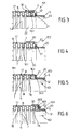
- Figures 3 and 4 show two similar variations 101 and 102 of joint 1. As the joint is symmetrical both cylindrically and axially, only the top half of one end of the joint is shown in section in Figures 3 to 6.
- Joints 101 and 102 in Figures 3 and 4 differ from joint 1 in that the vibration-damping pad is in the form an an annular element 161 conjugate with the contour of undulations 7 and inserted in the annular gap between at least any two adjacent undulations (the end two in Figure 3, and two intermediate undulations in Figure 4) so as to cooperate on either side with the same.
- End pieces 4, 5 are the same as those of joint 1 in Figure 1.
- Figures 5 and 6 show a further two joints 103 and 104 wherein the vibration-damping pad is in the form of an annular element 163 presenting a substantially trapezoidal cross section, and fitted on to a cylindrical, smaller-diameter, nonundulated portion 62 of each end of bellows sleeve 6.
- Pad 163 is gripped axially between an end undulation 7a of sleeve 6 and an annular shoulder 21 of the corresponding end piece 4, 5 (only end piece 5 shown) so as to grip against shoulder 21 a corresponding portion of end portion 11, 12 (only portion 12 shown) of sheath 8.
- Sleeve 6 is the same as that of joint 100 in Figure 2; end piece 5 (like end piece 4 not shown) is defined by a tube 20 upset on cylindrical end 62 of sleeve 6 so as to grip the corresponding end portion of end 12 of sheath 8 on to cylindrical end 62; and shoulder 21 is defined by an upset, bent portion 303 of tube 20.
- a further wire mesh pad 161 (optional and therefore hatched in Figure 5) is preferably inserted between any two undulations 7 of bellow sleeve 6 as for joint 102 in Figure 4.
- portion 303 is L-shaped so as to include an annular sleeve portion 30 similar to that of Figure 1 but formed in one piece with tube 20 and which provides for externally gripping annular vibration-damping pad 163 with sheath 8 in between.
Landscapes
- Engineering & Computer Science (AREA)
- General Engineering & Computer Science (AREA)
- Mechanical Engineering (AREA)
- Chemical & Material Sciences (AREA)
- Combustion & Propulsion (AREA)
- Joints Allowing Movement (AREA)
- Exhaust Silencers (AREA)
Abstract
Description
- The present invention relates to a flexible vibration-damping joint for connecting pipe portions in fluidtight, mechanically "decoupled" manner, and fittable in particular to the exhaust pipe of an internal combustion engine vehicle, for connecting the end pipe portion of the exhaust manifold of the engine to the inlet pipe portion of the catalyst.
- Here and hereinafter, the term "mechanically decoupled" is intended to mean the ability of the joint to mechanically connect two end-to-end pipe portions without transmitting any noticeable vibration between them, and in particular in such a manner as to protect the catalyst against vibration of the engine, while at the same time permitting relative axial and torsional movement of the connected pipe portions as a consequence, for example, of differing thermal expansion.
- Numerous types of flexible joints are known for fluidtight connecting two portions of a vehicle exhaust pipe. One type features a flexible undulated fluidtight connecting sleeve, and supporting parts fittable to the ends of the pipe portions so as to grip one another and form box type pockets housing vibration-damping pads made of compressed wire known as wire mesh. Another known type consists simply of a flexible undulated sleeve with a flexible braided wire outer sheath, both fitted in fluidtight manner to two rigid tubular end pieces in turn fitted to the pipe portions for connection.
- The first type provides for good connection and good mechanical "decoupling" of the pipe portions, but is complex in design, relatively bulky, and expensive to produce; whereas the second is compact and cheap to produce, but provides for only a limited amount of vibration damping, all of which depends on the elasticity of the undulated sleeve.
- It is an object of the present invention to provide a flexible vibration-damping joint for fluidtight connecting two end-to-end pipe portions, and which at the same time is compact, cheap to produce, and provides for a good degree of vibration damping efficiency.
- According to the present invention, there is provided a flexible vibration-damping joint for mechanical, fluidtight connection of two pipe portions, in particular two portions of a vehicle exhaust pipe; the joint comprising: a pair of substantially rigid, tubular end pieces fittable to respective opposite facing ends of the pipe portions; a metal bellows sleeve presenting a number of undulations for rendering it elastically deformable, and the opposite ends of which are connected integral with respective said end pieces; and a braided wire sheath externally covering the bellows sleeve and also connected at opposite ends to said end pieces; characterized in that at least one annular vibration-damping pad made of compressed wire is inserted between the bellows sleeve and the braided wire sheath.
- According to a first embodiment, the vibration-damping pad is in the form of a cylindrical sleeve of such a length as to cooperate with all or at least some of the undulations of the bellows sleeve, and is inserted and gripped between respective peaks of the bellows sleeve undulations and the inner lateral surface of the braided wire sheath.
- According to a second embodiment, the vibration-damping pad is in the form of an annular element conjugate with the contour of the bellows sleeve undulations, and is inserted in the annular gap between at least any two adjacent undulations so as to cooperate on either side with the same.
- According to a third embodiment, the vibration-damping pad is in the form of an annular element fitted to a smaller-diameter, nonundulated, cylindrical portion of the bellows sleeve, and is gripped between an end undulation of the bellows sleeve and an annular shoulder on the corresponding end piece so as to grip a corresponding end portion of the braided wire sheath against the shoulder.
- As such, a highly effective vibration-damping, and at any rate flexible, element is gripped firmly between parts of the braided wire sheath - possibly also gripped externally by respective portions of the end pieces - and parts of the bellows sleeve, in particular the peaks or sides of the undulations.
- The resulting joint is therefore extremely straightforward in design, compact, and cheap and easy to produce, while at the same time providing for effective mechanical decoupling of the connected pipe portions: on the one hand, by absorbing part of the work load, the braided wire sheath reduces the load on the bellows sleeve while at the same time shockproofing and weatherproofing it externally; and, on the other, by virtue of inserting the wire mesh pads, the braided wire sheath in no way affects the capacity of the bellows sleeve to permit relative movement of the connected pipe portions, but limits the amount of relative movement so as to safeguard the bellows sleeve against breakage.
- Finally, the wire mesh pad, inserted according to the invention between respective portions (peaks or sides) of one or more undulations and the braided wire sheath, provides for preventing, or at least greatly reducing, the transmission of vibration from one pipe portion to the other along the bellows sleeve, but without impairing the flexibility of the joint.
- A number of non-limiting embodiments of the present invention will be described by way of example with reference to the accompanying drawings, in which:
- Figure 1 shows a partially sectioned longitudinal view of a flexible joint in accordance with the present invention;
- Figure 2 shows a variation of the Figure 1 joint;
- Figures 3, 4, 5 and 6 show the same detail of four possible variations of the joint according to the present invention.
- Number 1 in Figure 1 indicates a vibration-damping joint for mechanical, fluidtight connection of two
pipe portions 2 and 3 (shown by the dotted lines), and in particular the exhaustmanifold end portion 2 and the catalyst inlet portion 3 of a pipe forming part of a known vehicle exhaust system (not shown) and along which the exhaust gas produced by the internal combustion engine (not shown) of the vehicle flows in the direction shown by the arrow. - Joint 1 comprises a pair of tubular, substantially
rigid end pieces 4 and 5 fittable, e.g. weldable, in known manner to respective opposite facing ends ofpipe portions 2 and 3; ametal bellows sleeve 6 presenting a number ofundulations 7 for rendering it elastically deformable; and a braidedwire sheath 8 externally coveringbellows sleeve 6. Theopposite ends 9 and 10 of bellows sleeve 6 - in the example shown, formed by incomplete end undulations 7 - and the correspondingopposite ends sheath 8 are connected integral withrespective end pieces 4 and 5 so that joint 1 forms one piece. - According to the invention, between
bellows sleeve 6 and braidedwire sheath 8, there is inserted at least one annular vibration-damping pad 16 made of compressed wire known as wire mesh and marketed in the form of annular pads available in any shape and size. - In the Figure 1 embodiment, vibration-
camping pad 16 is in the form of a cylindrical sleeve of such a length as to cooperate with all (or only some) ofundulations 7 ofbellows sleeve 6, includingincomplete end undulations 9 and 10; and is inserted and gripped betweenrespective peaks 17 ofundulations 7 ofsleeve 6 and the substantially cylindrical, innerlateral surface 18 ofbraided wire sheath 8. - Each
end piece 4, 5 is so formed as to comprise acylindrical tube portion 20 for connection to arespective pipe portion 2, 3; and anaxial shoulder 21 formed by permanently deforming a respective annular portion oftube portion 20. In the example shown, theportion defining shoulder 21 is a crimped intermediate portion oftube portion 20, and eachtube portion 20 terminates towardssleeve 6 with acylindrical end portion 22 having an outside diameter substantially equal to the minimum inside diameter ofbellows sleeve 6.Sleeve 6 presents at least some of itsend undulations 7 resting onend portions 22, and terminates withends 9 and 10 resting against shoulders 21 - in the example shown, against the radially-outer edge ofshoulders 21. - Each
end piece 4, 5 comprises anannular portion 30 superimposed oncorresponding end sheath 8, and defined, in the Figure 1 embodiment, by a cylindrical ring or sleeve formed separately fromtube portion 20 and having an inside diameter greater than the outside diameter ofsleeve 6.Rings 30 are fitted externally on to an axial portion ofsheath 8 substantially equal to the length ofend portions 22, and are upset onsheat 8 so as togrip ends sheath 8 againstpeaks 17 ofunderlying undulations pad 16 betweenends peaks 17 ofundulations 7 and/or 9, 10 respectively.Rings 30 are also connected toadjacent shoulders 21 byrespective weld beads 32 which are thick enough to also secureends sheath 8 andends 9, 10 ofsleeve 6 to the outer edge ofshoulders 21 without affectingwire mesh pad 16. - Reference will now be made to Figures 2 to 6 wherein any details similar or identical to those already described are indicated for the sake of simplicity using the same numbering system.
- The Figure 2 variation shows a joint 100 identical to joint 1 described above, with the exception of the following:
undulations 7 ofsleeve 6 are all alike, with noincomplete end undulations 9, 10;sleeve 6 terminates with two opposite ends 61, 62, each defined by a cylindrical, smaller-diameter, nonundulated portion ofsleeve 6; andend pieces 4, 5 are each defined by atube 20 upset so as to grip ends 11, 12 ofsheath 8 on the cylindrical ends 61, 62 ofsleeve 6 without grippingpad 16 which is shorter thansheath 8 and terminates at each end at thelast undulation 7 ofsleeve 6. - Moreover, the end edges of
tubes 20 facingsleeve 6 are bent to formannular portions 301 which replaceportions 30 in cooperating withsheath 8 and, at the same time, defineshoulders 21 which, in this case however, provide solely for axially securingsheath 8. - Figures 3 and 4 show two
similar variations -
Joints annular element 161 conjugate with the contour ofundulations 7 and inserted in the annular gap between at least any two adjacent undulations (the end two in Figure 3, and two intermediate undulations in Figure 4) so as to cooperate on either side with the same. End pieces 4, 5 (only end piece 5 shown) are the same as those of joint 1 in Figure 1. - Figures 5 and 6 show a further two
joints annular element 163 presenting a substantially trapezoidal cross section, and fitted on to a cylindrical, smaller-diameter,nonundulated portion 62 of each end ofbellows sleeve 6.Pad 163 is gripped axially between anend undulation 7a ofsleeve 6 and anannular shoulder 21 of the corresponding end piece 4, 5 (only end piece 5 shown) so as to grip against shoulder 21 a corresponding portion ofend portion 11, 12 (onlyportion 12 shown) ofsheath 8. -
Sleeve 6 is the same as that of joint 100 in Figure 2; end piece 5 (like end piece 4 not shown) is defined by atube 20 upset oncylindrical end 62 ofsleeve 6 so as to grip the corresponding end portion ofend 12 ofsheath 8 on tocylindrical end 62; andshoulder 21 is defined by an upset,bent portion 303 oftube 20. - In the Figure 5 variation, a further wire mesh pad 161 (optional and therefore hatched in Figure 5) is preferably inserted between any two
undulations 7 ofbellow sleeve 6 as for joint 102 in Figure 4. - In the Figure 6 variation,
portion 303 is L-shaped so as to include anannular sleeve portion 30 similar to that of Figure 1 but formed in one piece withtube 20 and which provides for externally gripping annular vibration-dampingpad 163 withsheath 8 in between.
Claims (8)
Applications Claiming Priority (2)
| Application Number | Priority Date | Filing Date | Title |
|---|---|---|---|
| ITTO930245U | 1993-11-09 | ||
| ITTO930245 IT231517Y1 (en) | 1993-11-09 | 1993-11-09 | ANTIVIBRATION FLEXIBLE JOINT, IN PARTICULAR TO EQUIP VEHICLE EXHAUST PIPES. |
Publications (3)
| Publication Number | Publication Date |
|---|---|
| EP0657683A2 true EP0657683A2 (en) | 1995-06-14 |
| EP0657683A3 EP0657683A3 (en) | 1996-07-24 |
| EP0657683B1 EP0657683B1 (en) | 1999-05-26 |
Family
ID=11411371
Family Applications (1)
| Application Number | Title | Priority Date | Filing Date |
|---|---|---|---|
| EP19940117689 Expired - Lifetime EP0657683B1 (en) | 1993-11-09 | 1994-11-09 | Flexible vibration-damping joint, particularly for vehicle exhaust pipes |
Country Status (4)
| Country | Link |
|---|---|
| EP (1) | EP0657683B1 (en) |
| DE (1) | DE69418680T2 (en) |
| ES (1) | ES2133462T3 (en) |
| IT (1) | IT231517Y1 (en) |
Cited By (18)
| Publication number | Priority date | Publication date | Assignee | Title |
|---|---|---|---|---|
| GB2311110A (en) * | 1996-03-15 | 1997-09-17 | Sankei Giken Kogyo Kk | Flexible joint |
| FR2753773A1 (en) * | 1996-09-25 | 1998-03-27 | Hydrometal | DECOUPLER FIT TO BE INTERPOSED BETWEEN TWO TUBULERS |
| EP0848143A1 (en) * | 1996-12-13 | 1998-06-17 | FLEXIDER S.p.A. | Flexible decoupling joint, particularly for vehicle exhaust pipes |
| EP0859134A1 (en) * | 1997-02-18 | 1998-08-19 | Witzenmann GmbH Metallschlauch-Fabrik Pforzheim | Flexible connecting element for tubular parts |
| DE19919715A1 (en) * | 1999-04-30 | 2000-11-02 | Witzenmann Metallschlauchfab | Refrigerant line for air conditioning systems |
| DE10014560A1 (en) * | 2000-03-23 | 2001-10-11 | Witzenmann Metallschlauchfab | Hose system comprises corrugated hose, connector which fits into this with collar which fits against its end, section of braided hose being fitted over joint |
| US6354332B1 (en) | 1999-04-30 | 2002-03-12 | Witzenmann Gmbh, Metallschlauch-Fabrik Pforzheim | Coolant line for air conditioning systems |
| EP2042702A1 (en) | 2007-09-27 | 2009-04-01 | Witzenmann GmbH | Dampening assembly |
| EP2042701A1 (en) | 2007-09-27 | 2009-04-01 | Witzenmann GmbH | Dampening assembly |
| WO2011148252A1 (en) | 2010-05-25 | 2011-12-01 | Flexider S.R.L. | Decoupling joint for exhaust pipings of endothermic engines |
| WO2011157355A1 (en) * | 2010-06-15 | 2011-12-22 | Boa Balg- Und Kompensatoren-Technologie Gmbh | Flexible pipe element |
| WO2011161524A1 (en) | 2010-06-21 | 2011-12-29 | Flexider S.R.L. | Decoupling joint for exhaust pipings of endothermic engines |
| CN102537543A (en) * | 2010-12-23 | 2012-07-04 | 浙江永杰管业科技有限公司 | Stainless steel air conditioner corrugated pipe |
| CN103133812A (en) * | 2013-03-26 | 2013-06-05 | 江苏亚星波纹管有限公司 | Novel pipeline compensator |
| WO2016027144A1 (en) * | 2014-08-21 | 2016-02-25 | American Boa Inc. | Floating load ring for flexible joint |
| EP3002493A1 (en) | 2014-09-30 | 2016-04-06 | FLEXIDER S.r.l. | Thermally insulated coupling device for exhaust pipes of endothermic engines |
| WO2016110737A1 (en) * | 2015-01-09 | 2016-07-14 | American Boa Inc. | External tunable damping rings for flexible coupling |
| WO2026068280A1 (en) * | 2024-09-24 | 2026-04-02 | Boa Metal Solutions Gmbh | Method for producing a fluid line, and such a fluid line |
Families Citing this family (2)
| Publication number | Priority date | Publication date | Assignee | Title |
|---|---|---|---|---|
| DE202007003805U1 (en) * | 2007-03-14 | 2008-07-17 | Witzenmann Gmbh | Structure-borne sound decoupling element for the exhaust system of a motor vehicle |
| DE202010006231U1 (en) | 2010-04-29 | 2010-08-05 | Boa Balg- Und Kompensatoren-Technologie Gmbh | Flexible conduit element |
Family Cites Families (5)
| Publication number | Priority date | Publication date | Assignee | Title |
|---|---|---|---|---|
| US4659117A (en) * | 1982-08-10 | 1987-04-21 | Iwk Regler Und Kompensatoren Gmbh | Flexible coupling for pipes in exhaust systems of motor vehicles |
| US5145215A (en) * | 1991-04-26 | 1992-09-08 | Senior Engineering Investments, B.V. | Flexible coupler apparatus |
| IT1250556B (en) * | 1991-12-24 | 1995-04-20 | Flexider Spa | FLEXIBLE ANTIVIBRATION DUCT WITH FLAT CROSS SECTION. |
| DE4224745A1 (en) * | 1992-07-27 | 1994-02-03 | Witzenmann Metallschlauchfab | Pipe joint |
| DE4415860A1 (en) * | 1994-05-05 | 1995-11-16 | Witzenmann Metallschlauchfab | Flexible pipe element for exhaust pipes of internal combustion engines in motor vehicles |
-
1993
- 1993-11-09 IT ITTO930245 patent/IT231517Y1/en active IP Right Grant
-
1994
- 1994-11-09 ES ES94117689T patent/ES2133462T3/en not_active Expired - Lifetime
- 1994-11-09 DE DE1994618680 patent/DE69418680T2/en not_active Expired - Lifetime
- 1994-11-09 EP EP19940117689 patent/EP0657683B1/en not_active Expired - Lifetime
Cited By (25)
| Publication number | Priority date | Publication date | Assignee | Title |
|---|---|---|---|---|
| GB2311110B (en) * | 1996-03-15 | 2000-03-08 | Sankei Giken Kogyo Kk | Flexible joint |
| GB2311110A (en) * | 1996-03-15 | 1997-09-17 | Sankei Giken Kogyo Kk | Flexible joint |
| DE19709403B4 (en) * | 1996-03-15 | 2012-11-15 | Sankei Giken Kogyo K.K. | Flexible connection |
| FR2753773A1 (en) * | 1996-09-25 | 1998-03-27 | Hydrometal | DECOUPLER FIT TO BE INTERPOSED BETWEEN TWO TUBULERS |
| EP0833091A1 (en) * | 1996-09-25 | 1998-04-01 | Hydrometal | Decoupling device possible to be inserted between two pipe unions |
| EP0848143A1 (en) * | 1996-12-13 | 1998-06-17 | FLEXIDER S.p.A. | Flexible decoupling joint, particularly for vehicle exhaust pipes |
| US6296282B1 (en) | 1997-02-18 | 2001-10-02 | Witzenmann Gmbh Metallschlauch-Fabrik Pforzheim | Articulated connecting element for piping elements |
| EP0859134A1 (en) * | 1997-02-18 | 1998-08-19 | Witzenmann GmbH Metallschlauch-Fabrik Pforzheim | Flexible connecting element for tubular parts |
| DE19919715A1 (en) * | 1999-04-30 | 2000-11-02 | Witzenmann Metallschlauchfab | Refrigerant line for air conditioning systems |
| JP2000337572A (en) * | 1999-04-30 | 2000-12-05 | Witzenmann Gmbh Metallschlauchfab Pforzheim | Refrigerant duct for air conditioner |
| US6354332B1 (en) | 1999-04-30 | 2002-03-12 | Witzenmann Gmbh, Metallschlauch-Fabrik Pforzheim | Coolant line for air conditioning systems |
| DE10014560C2 (en) * | 2000-03-23 | 2002-01-24 | Witzenmann Metallschlauchfab | Pipe element with a corrugated hose and connecting piece |
| DE10014560A1 (en) * | 2000-03-23 | 2001-10-11 | Witzenmann Metallschlauchfab | Hose system comprises corrugated hose, connector which fits into this with collar which fits against its end, section of braided hose being fitted over joint |
| EP2042702A1 (en) | 2007-09-27 | 2009-04-01 | Witzenmann GmbH | Dampening assembly |
| EP2042701A1 (en) | 2007-09-27 | 2009-04-01 | Witzenmann GmbH | Dampening assembly |
| WO2011148252A1 (en) | 2010-05-25 | 2011-12-01 | Flexider S.R.L. | Decoupling joint for exhaust pipings of endothermic engines |
| WO2011157355A1 (en) * | 2010-06-15 | 2011-12-22 | Boa Balg- Und Kompensatoren-Technologie Gmbh | Flexible pipe element |
| WO2011161524A1 (en) | 2010-06-21 | 2011-12-29 | Flexider S.R.L. | Decoupling joint for exhaust pipings of endothermic engines |
| CN102537543A (en) * | 2010-12-23 | 2012-07-04 | 浙江永杰管业科技有限公司 | Stainless steel air conditioner corrugated pipe |
| CN103133812A (en) * | 2013-03-26 | 2013-06-05 | 江苏亚星波纹管有限公司 | Novel pipeline compensator |
| WO2016027144A1 (en) * | 2014-08-21 | 2016-02-25 | American Boa Inc. | Floating load ring for flexible joint |
| US11306853B2 (en) | 2014-08-21 | 2022-04-19 | American Boa, Inc. | Floating load ring for flexible joint |
| EP3002493A1 (en) | 2014-09-30 | 2016-04-06 | FLEXIDER S.r.l. | Thermally insulated coupling device for exhaust pipes of endothermic engines |
| WO2016110737A1 (en) * | 2015-01-09 | 2016-07-14 | American Boa Inc. | External tunable damping rings for flexible coupling |
| WO2026068280A1 (en) * | 2024-09-24 | 2026-04-02 | Boa Metal Solutions Gmbh | Method for producing a fluid line, and such a fluid line |
Also Published As
| Publication number | Publication date |
|---|---|
| EP0657683A3 (en) | 1996-07-24 |
| DE69418680D1 (en) | 1999-07-01 |
| EP0657683B1 (en) | 1999-05-26 |
| DE69418680T2 (en) | 1999-12-09 |
| ITTO930245U1 (en) | 1995-05-09 |
| IT231517Y1 (en) | 1999-08-03 |
| ITTO930245V0 (en) | 1993-11-09 |
| ES2133462T3 (en) | 1999-09-16 |
Similar Documents
| Publication | Publication Date | Title |
|---|---|---|
| EP0657683B1 (en) | Flexible vibration-damping joint, particularly for vehicle exhaust pipes | |
| AU697712B2 (en) | Flexible coupler apparatus | |
| US8500172B2 (en) | Double cover-center cushion decoupler | |
| US5506376A (en) | Apparatus for absorbing vibrations in an exhaust system of a vehicle | |
| EP1315887B1 (en) | Exhaust pipe decoupler for vehicles | |
| US6109661A (en) | Flexible coupler apparatus | |
| US5167430A (en) | Automotive exhaust system decoupler with resilient sleeve | |
| US5971439A (en) | Flexible coupler apparatus | |
| JPH10220221A (en) | Flexible conduit element | |
| US5992896A (en) | Flexible coupler apparatus | |
| US6047993A (en) | Arrangement for connection pipe pieces and method of making same | |
| US20060017285A1 (en) | Flexible tube for an exhaust pipe of an automobile | |
| JPH08233175A (en) | Device for movably connecting conduit ends | |
| EP1169555B1 (en) | Vehicle exhaust system | |
| EP0848143B1 (en) | Flexible decoupling joint, particularly for vehicle exhaust pipes | |
| EP0860590A1 (en) | A flexible tube with a corrugated wall for uncoupling motor-vehicle exhaust pipes | |
| EP0989289A1 (en) | Flexible vibration-decoupling joint, in particular for exhaust pipes in motor vehicles | |
| EP0889210B1 (en) | Flexible undulated-walled conduit for decoupling vehicle engine exhaust pipes | |
| EP1152135A2 (en) | Flexible vibration-damping decoupling joint, in particular for vehicle exhaust pipes | |
| KR200183322Y1 (en) | Bellows for automobile exhaust pipe | |
| JPH08303664A (en) | Spherical joint | |
| JP3755212B2 (en) | Flexible joint for automobile exhaust pipe | |
| WO1993004270A1 (en) | Hollow pivotable coupling | |
| JP2857354B2 (en) | Bellows joint of exhaust pipe for internal combustion engine | |
| WO1998030824A1 (en) | Flexible coupler apparatus |
Legal Events
| Date | Code | Title | Description |
|---|---|---|---|
| PUAI | Public reference made under article 153(3) epc to a published international application that has entered the european phase |
Free format text: ORIGINAL CODE: 0009012 |
|
| AK | Designated contracting states |
Kind code of ref document: A2 Designated state(s): DE ES FR GB IT SE |
|
| PUAL | Search report despatched |
Free format text: ORIGINAL CODE: 0009013 |
|
| AK | Designated contracting states |
Kind code of ref document: A3 Designated state(s): DE ES FR GB IT SE |
|
| 17P | Request for examination filed |
Effective date: 19960928 |
|
| 17Q | First examination report despatched |
Effective date: 19970418 |
|
| GRAG | Despatch of communication of intention to grant |
Free format text: ORIGINAL CODE: EPIDOS AGRA |
|
| GRAG | Despatch of communication of intention to grant |
Free format text: ORIGINAL CODE: EPIDOS AGRA |
|
| GRAH | Despatch of communication of intention to grant a patent |
Free format text: ORIGINAL CODE: EPIDOS IGRA |
|
| GRAH | Despatch of communication of intention to grant a patent |
Free format text: ORIGINAL CODE: EPIDOS IGRA |
|
| GRAA | (expected) grant |
Free format text: ORIGINAL CODE: 0009210 |
|
| AK | Designated contracting states |
Kind code of ref document: B1 Designated state(s): DE ES FR GB IT SE |
|
| REF | Corresponds to: |
Ref document number: 69418680 Country of ref document: DE Date of ref document: 19990701 |
|
| ET | Fr: translation filed | ||
| ITF | It: translation for a ep patent filed | ||
| REG | Reference to a national code |
Ref country code: ES Ref legal event code: FG2A Ref document number: 2133462 Country of ref document: ES Kind code of ref document: T3 |
|
| PLBQ | Unpublished change to opponent data |
Free format text: ORIGINAL CODE: EPIDOS OPPO |
|
| PLBI | Opposition filed |
Free format text: ORIGINAL CODE: 0009260 |
|
| PLBF | Reply of patent proprietor to notice(s) of opposition |
Free format text: ORIGINAL CODE: EPIDOS OBSO |
|
| 26 | Opposition filed |
Opponent name: WITZENMANN GMBH METALLSCHLAUCH-FABRIK PFORZHEIM Effective date: 20000217 |
|
| PLBF | Reply of patent proprietor to notice(s) of opposition |
Free format text: ORIGINAL CODE: EPIDOS OBSO |
|
| PLAW | Interlocutory decision in opposition |
Free format text: ORIGINAL CODE: EPIDOS IDOP |
|
| PLAW | Interlocutory decision in opposition |
Free format text: ORIGINAL CODE: EPIDOS IDOP |
|
| APAC | Appeal dossier modified |
Free format text: ORIGINAL CODE: EPIDOS NOAPO |
|
| APAE | Appeal reference modified |
Free format text: ORIGINAL CODE: EPIDOS REFNO |
|
| APAC | Appeal dossier modified |
Free format text: ORIGINAL CODE: EPIDOS NOAPO |
|
| REG | Reference to a national code |
Ref country code: GB Ref legal event code: IF02 |
|
| PLAW | Interlocutory decision in opposition |
Free format text: ORIGINAL CODE: EPIDOS IDOP |
|
| PLAB | Opposition data, opponent's data or that of the opponent's representative modified |
Free format text: ORIGINAL CODE: 0009299OPPO |
|
| PLBQ | Unpublished change to opponent data |
Free format text: ORIGINAL CODE: EPIDOS OPPO |
|
| R26 | Opposition filed (corrected) |
Opponent name: WITZENMANN GMBHMETALLSCHLAUCH-FABRIK PFORZHEIM Effective date: 20000217 |
|
| APBU | Appeal procedure closed |
Free format text: ORIGINAL CODE: EPIDOSNNOA9O |
|
| PLCK | Communication despatched that opposition was rejected |
Free format text: ORIGINAL CODE: EPIDOSNREJ1 |
|
| PLBN | Opposition rejected |
Free format text: ORIGINAL CODE: 0009273 |
|
| STAA | Information on the status of an ep patent application or granted ep patent |
Free format text: STATUS: OPPOSITION REJECTED |
|
| 27O | Opposition rejected |
Effective date: 20031119 |
|
| APAH | Appeal reference modified |
Free format text: ORIGINAL CODE: EPIDOSCREFNO |
|
| PGFP | Annual fee paid to national office [announced via postgrant information from national office to epo] |
Ref country code: FR Payment date: 20121130 Year of fee payment: 19 |
|
| PGFP | Annual fee paid to national office [announced via postgrant information from national office to epo] |
Ref country code: SE Payment date: 20121113 Year of fee payment: 19 Ref country code: ES Payment date: 20121029 Year of fee payment: 19 Ref country code: IT Payment date: 20121126 Year of fee payment: 19 Ref country code: GB Payment date: 20121107 Year of fee payment: 19 |
|
| PGFP | Annual fee paid to national office [announced via postgrant information from national office to epo] |
Ref country code: DE Payment date: 20121228 Year of fee payment: 19 |
|
| REG | Reference to a national code |
Ref country code: DE Ref legal event code: R119 Ref document number: 69418680 Country of ref document: DE |
|
| REG | Reference to a national code |
Ref country code: SE Ref legal event code: EUG |
|
| GBPC | Gb: european patent ceased through non-payment of renewal fee |
Effective date: 20131109 |
|
| REG | Reference to a national code |
Ref country code: FR Ref legal event code: ST Effective date: 20140731 |
|
| PG25 | Lapsed in a contracting state [announced via postgrant information from national office to epo] |
Ref country code: DE Free format text: LAPSE BECAUSE OF NON-PAYMENT OF DUE FEES Effective date: 20140603 Ref country code: IT Free format text: LAPSE BECAUSE OF NON-PAYMENT OF DUE FEES Effective date: 20131109 Ref country code: SE Free format text: LAPSE BECAUSE OF NON-PAYMENT OF DUE FEES Effective date: 20131110 |
|
| REG | Reference to a national code |
Ref country code: DE Ref legal event code: R119 Ref document number: 69418680 Country of ref document: DE Effective date: 20140603 |
|
| PG25 | Lapsed in a contracting state [announced via postgrant information from national office to epo] |
Ref country code: GB Free format text: LAPSE BECAUSE OF NON-PAYMENT OF DUE FEES Effective date: 20131109 Ref country code: FR Free format text: LAPSE BECAUSE OF NON-PAYMENT OF DUE FEES Effective date: 20131202 |
|
| REG | Reference to a national code |
Ref country code: ES Ref legal event code: FD2A Effective date: 20150401 |
|
| PG25 | Lapsed in a contracting state [announced via postgrant information from national office to epo] |
Ref country code: ES Free format text: LAPSE BECAUSE OF NON-PAYMENT OF DUE FEES Effective date: 20131110 |