EP0657677A2 - Self-tightening clamp structure - Google Patents
Self-tightening clamp structure Download PDFInfo
- Publication number
- EP0657677A2 EP0657677A2 EP94117465A EP94117465A EP0657677A2 EP 0657677 A2 EP0657677 A2 EP 0657677A2 EP 94117465 A EP94117465 A EP 94117465A EP 94117465 A EP94117465 A EP 94117465A EP 0657677 A2 EP0657677 A2 EP 0657677A2
- Authority
- EP
- European Patent Office
- Prior art keywords
- slot
- clamp structure
- tongue
- extension
- opening
- Prior art date
- Legal status (The legal status is an assumption and is not a legal conclusion. Google has not performed a legal analysis and makes no representation as to the accuracy of the status listed.)
- Granted
Links
Images
Classifications
-
- F—MECHANICAL ENGINEERING; LIGHTING; HEATING; WEAPONS; BLASTING
- F16—ENGINEERING ELEMENTS AND UNITS; GENERAL MEASURES FOR PRODUCING AND MAINTAINING EFFECTIVE FUNCTIONING OF MACHINES OR INSTALLATIONS; THERMAL INSULATION IN GENERAL
- F16L—PIPES; JOINTS OR FITTINGS FOR PIPES; SUPPORTS FOR PIPES, CABLES OR PROTECTIVE TUBING; MEANS FOR THERMAL INSULATION IN GENERAL
- F16L33/00—Arrangements for connecting hoses to rigid members; Rigid hose connectors, i.e. single members engaging both hoses
- F16L33/02—Hose-clips
- F16L33/03—Self-locking elastic clips
-
- Y—GENERAL TAGGING OF NEW TECHNOLOGICAL DEVELOPMENTS; GENERAL TAGGING OF CROSS-SECTIONAL TECHNOLOGIES SPANNING OVER SEVERAL SECTIONS OF THE IPC; TECHNICAL SUBJECTS COVERED BY FORMER USPC CROSS-REFERENCE ART COLLECTIONS [XRACs] AND DIGESTS
- Y10—TECHNICAL SUBJECTS COVERED BY FORMER USPC
- Y10T—TECHNICAL SUBJECTS COVERED BY FORMER US CLASSIFICATION
- Y10T24/00—Buckles, buttons, clasps, etc.
- Y10T24/14—Bale and package ties, hose clamps
- Y10T24/1457—Metal bands
- Y10T24/1482—Ratchet and tool tightened band clamp
-
- Y—GENERAL TAGGING OF NEW TECHNOLOGICAL DEVELOPMENTS; GENERAL TAGGING OF CROSS-SECTIONAL TECHNOLOGIES SPANNING OVER SEVERAL SECTIONS OF THE IPC; TECHNICAL SUBJECTS COVERED BY FORMER USPC CROSS-REFERENCE ART COLLECTIONS [XRACs] AND DIGESTS
- Y10—TECHNICAL SUBJECTS COVERED BY FORMER USPC
- Y10T—TECHNICAL SUBJECTS COVERED BY FORMER US CLASSIFICATION
- Y10T24/00—Buckles, buttons, clasps, etc.
- Y10T24/14—Bale and package ties, hose clamps
- Y10T24/1457—Metal bands
- Y10T24/1484—Spring closed band clamp
-
- Y—GENERAL TAGGING OF NEW TECHNOLOGICAL DEVELOPMENTS; GENERAL TAGGING OF CROSS-SECTIONAL TECHNOLOGIES SPANNING OVER SEVERAL SECTIONS OF THE IPC; TECHNICAL SUBJECTS COVERED BY FORMER USPC CROSS-REFERENCE ART COLLECTIONS [XRACs] AND DIGESTS
- Y10—TECHNICAL SUBJECTS COVERED BY FORMER USPC
- Y10T—TECHNICAL SUBJECTS COVERED BY FORMER US CLASSIFICATION
- Y10T24/00—Buckles, buttons, clasps, etc.
- Y10T24/44—Clasp, clip, support-clamp, or required component thereof
- Y10T24/44009—Gripping member adapted for tool actuation or release
Landscapes
- General Engineering & Computer Science (AREA)
- Engineering & Computer Science (AREA)
- Mechanical Engineering (AREA)
- Clamps And Clips (AREA)
- Flanged Joints, Insulating Joints, And Other Joints (AREA)
- Joining Of Building Structures In Genera (AREA)
- Joints That Cut Off Fluids, And Hose Joints (AREA)
- Tents Or Canopies (AREA)
- Lubricants (AREA)
- Shaping By String And By Release Of Stress In Plastics And The Like (AREA)
- Paper (AREA)
- Body Structure For Vehicles (AREA)
- Seal Device For Vehicle (AREA)
- Control And Other Processes For Unpacking Of Materials (AREA)
- Outer Garments And Coats (AREA)
Abstract
Description
- The present invention relates to a self-tightening clamp structure, and more particularly to a self-tightening reusable clamp structure which provides internal clamping surfaces devoid of steps, offsets or interruptions to assure a completely satisfactory fluid-tight connection.
- Self-tightening clamps, i.e., clamps made from spring wire or spring steel band material, which are also referred to in the art as constant-tension clamps, are known as such. In their simplest form, such clamps, which, by their inherent spring characteristics, normally tend to assume their closed clamping position, consist of spring wire with overlapping, outwardly extending ends, whereby the clamps are opened by forcing the overlapping outwardly extending ends toward one another. Once installed over a hose, the outwardly extending ends are released and the clamp will assume its clamping position. Self-tightening clamps made from band material are also known in the prior art. They usually consist of a tongue-like extension at one end and are preferably provided with a latching device at the other end to latch the clamp in its prestressed condition. The thus-opened latched clamps are shipped to the user who will install the open clamps and then release the latching engagement. The U.S. Patents 4,305,179; 4,425,681; 4,773,129; 4,858,279; 4,930,191; 4,930,192 and 4,996,749 are representative of prior art self-tightening clamps made from band material. All of these prior art clamps, however, involve an injury danger in use owing to outwardly extending parts thereof, not to mention lack of clamping surfaces devoid of discontinuities, steps or offsets.
- The clamps described in my prior U.S. Patent 5,203,809 represented a significant step in the direction toward greater safety coupled with reliable clamping action over the entire circumference. In particular, the clamp illustrated in Figures 24 through 30 has proved commercially successful. However, apart from being relatively complicated and costly to manufacture, its snap-like release from the latched position into the clamping position occasionally produces some sparking which is unacceptable within the area, for example, of gasoline lines and the like. Sparking danger can be reduced with the use of a lacquer cover layer on the surface of the clamp. However, such lacquer layer again increases the cost of the clamp.
- Accordingly, it is an object of the present invention to provide a self-tightening clamp of the type described above which eliminates by simple means the aforementioned shortcomings and drawbacks encountered in the prior art.
- Another object of the present invention resides in a self-tightening clamp which is so constructed and arranged that it can be released from its latched condition most conveniently with a positive guidance by the use of a tool, thereby preventing the snap-like return to the clamping action which might cause sparking.
- A further object of the present invention resides in a self-tightening clamp of the type described above which is extraordinarily simple in construction and low cost in manufacture.
- Still another object of the present invention resides in a self-tightening clamp which can be easily opened and closed under positive guidance with the use of the same tool.
- The underlying problems are solved in accordance with the present invention by a self-tightening clamp structure having a first clamping position and a second non-clamping position in which the clamping band is under prestress of its inherent spring characteristics. To latchingly hold the clamp structure in its second position, one end of the clamping band is provided with a tongue-like extension while the other end is provided with two longitudinally extending, slot-like openings following one another in the longitudinal direction of the clamping band by way of a constriction, whereby one of the slot-like openings is wider than the tongue-like extension and the other is narrower than the tongue-like extension. One of the slot-like openings is thereby offset in the radial direction with respect to at least a part of the other slot-like opening. Additionally, to enhance the spring characteristics, the clamping band may be provided with a longitudinally extending reinforcing groove.
- These and other objects, features and advantages of the present invention will become more apparent from the following description which shows, for purposes of illustration only, one embodiment in accordance with the present invention and wherein:
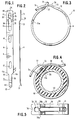
- Figure 1 is a top plan view on a self-tightening clamp structure in accordance with the present invention;
- Figure 2 is a side elevational view of the clamp structure of Figure 1;
- Figure 3 is an axial elevational view of the clamp structures of Figures 1 and 2 in the latched, open condition thereof;
- Figure 4 is an axial elevational view, similar to Figure 3, but showing the clamp structure in the closed clamping condition in which it clamps a tubular member onto a fixed part; and
- Figure 5 is a top plan view on the clamp structure shown in Figure 4.
- Referring now to the drawing wherein like reference numerals are used throughout the various views to designate like parts, the clamp structure generally designated by
reference numeral 10 consists of aclamping band 11 which is provided at one end thereof with a tongue-like extension generally designated byreference numeral 20. The bent-upend portion 21 of the tongue-like extension 20 is provided in its rounded-off end with a tool-engaging notch 22. The full band width of theclamping band 11 passes over into the tongue-like extension by way of taperingportions clamping band 11 and rounded-off with a radius of curvature R₁ where these taperingportions like extension 20. The opposite end portion of the clamp structure generally designated byreference numeral 30 includes afirst section 31 connected with asecond section 32 by way of a step-like connectingsection 33. Theend portion 30 is provided at its rounded-off free end with a tool-engagingnotch 34 and, proceeding from that end of the clamping band in the direction toward the tongue-like extension 20, is provided with a firstelongated opening 35 and a secondelongated opening 36 in communication by way of anarrow constriction 37 formed by inwardly extendingprojections 38a and 38b (Figure 5). The tongue-like extension 20 tapers in theend portion 21 in the direction toward its free end, whereby such taper may be formed by a part of a circular arc of radius R2 on both sides thereof. Theclamping band 11 is further provided intermediate the slot-like opening 36 and the tongue-like extension 20 with twoopenings openings - The width c, i.e., dimension in the transverse direction of the clamping band, of the slot-
like opening 36 is thereby greater than the width dimension d of the slot-like opening 35 and is also larger than the width b of the tongue-like extension so that the tongue-like extension can slide freely withinslot 36 during opening and subsequent release into the clamping position of the clamp structure. On the other hand, the width d of the slot-like opening 35 is preferably somewhat smaller than the width b of the tongue-like extension 20 so that only a part of thetapered end portion 21 can extend through the same. This will facilitate release of the clamp from its latched, open position as will be explained more fully hereinafter. - Figure 3 shows the clamp in its open latched position into which it has been forcibly displaced against the inherent springiness of the clamping band material by engagement of a tool as shown, for example, in Figures 31 to 33 of my prior U.S. Patent 5,203,809, in tool-
engaging notches clamp structure 10 as shown in Figure 3, is held in the open latched position by engagement of the taperingend portion 21 of the tongue-like extension 20 against the rounded end wall 35' of the slot-like opening 35. To release the clamp structure from its latched, open position in Figure 3, into the unlatched clamping position shown in Figures 4 and 5, the same tool is again engaged innotches free end 21 continues to be positively guided into the clamping position after being released from the latching position by lowering the protrudingend portion 21 to pass underneath theconstriction 37. By limiting the extent of projection of theend portion 21 through slot-like opening 35 which is controlled by the width dimensions d and b and by the tapering end-portion 21, release is facilitated by the fact that only the tip of the free end of the tongue-like extension which has to pass underneath theconstriction 37, extends through the slot-like opening 35. Figure 4 shows the installedclamp structure 10 in which it clampingly holds atubular member 40 such as a hose or axle boot on a fixedmember 50 such as a nipple or rotating member of a CV joint. - In a typical example which, however, is non-limitative of the present invention, the dimensions for a clamp structure intended to have an internal diameter in its clamping position of 26.5 mm. are as follows:
The length of the clamp structure is about 119.7 mm. while the width of theclamping band 11 is 10 mm. and its thickness is 1.2 mm. Theopening 35 has a width d of about 3 mm. and a length of about 8 mm. The distance from the rounded-off end of opening 35 to the corresponding end of the clamp structure is about 4 mm. The slot-like opening 36 has a length of about 20 mm. and a width c of about 4.5 mm. Theopening 14 is spaced with its larger rounded-off end at about 38 mm. from the corresponding end of the clamping band and has a length of about 12 mm. The end of theopening 14 with the smaller rounded-off portion is spaced from the end of the opening 15 with smaller rounded-off portion at about 29.2 mm. while the opening 15 also has a length of about 12 mm. and is spaced with its larger rounded-off end from the free end of the tongue-like portion 20 by about 28.5 mm. The tongue-like portion has a width b of about 4 mm. and a length of about 23.3 mm. including the taperingsurfaces end portion 21 are formed by a portion of a circular arc having a radius of curvature of about 2 mm. or greater while the tool-engaging notch 22 is formed by a radius of curvature of about 1 mm. to a depth of about 0.35 mm. The inclined sides of theopenings end portion 21 of the tongue-like extension is bent up at an angle of about 40° while the step-like portion 33 is bent-up at an angle of about 30° by way of rounded-off transitions having a radius of curvature of about 0.5 mm. In the installed condition, the firstouter end section 31 is spaced in the radial direction from the inner overlapped clamping band by a distance s of about 1.2 mm. (Figure 4). The length of the bent-upportion 21 is about 5 mm. A radius R₁ of about 1 mm. is used for the radius of curvature of the tool-engagingnotch 22 as also for the transition of the taperingsurfaces end portion 30 and the tool-engagingnotch 34. The larger rounded-off ends ofopenings openings like openings like extension 20 as also the use of the step-like portion 33 while the width of theconstriction 37 would permit the passage of one jaw of the tool. - The clamp structure of this invention is made of very hard material, both from stainless steel as also carbon steel which, if necessary, is hardened and galvanized or externally covered by a lacquer layer to protect against corrosion. A clamp made from stainless steel offers the advantage that the clamps leave the machine in completely finished condition without the need for after-treatment.
- The clamping band may also be provided with a reinforcing groove extending in the longitudinal direction substantially within the center to provide a stronger spring stiffness. The reinforcing groove may thereby be interrupted in the area of the
openings - Though the preferred manner of releasing the clamp structure of this invention from its open latched position is by means of a tool, such as shown in Figures 31-33 of my prior U.S. Patent 5,203,809, it would also be feasible to release the clamp by the application of a downwardly directed force on the
end portion 21 of the tongue-like extension 20 by the use of an appropriate tool. - Furthermore, the basic concept of this invention is also applicable to a clamp structure for fastening a hose or the like which has to be secured from the inside in the radially outward direction, i.e., in which the open latched position has a smaller diameter and the normal clamping position, a larger diameter. It is only necessary in that case to reverse the clamp system so that the clamping surfaces devoid of steps, offsets or discontinuities are now located on the outside, and the position of the
openings - While I have shown and described only one embodiment in accordance with the present invention, it is understood that the same is not limited thereto but is susceptible of numerous changes and modifications as known to those skilled in the art, and I therefore do not wish to be limited to the details shown and described herein but intend to cover all such changes and modifications as are encompassed by the scope of the appended claims.
Claims (12)
- A self-tightening clamp structure (10) having a first released position (Figure 4) in which the clamp structure exerts a clamping action and a second position (Figure 3) in which the clamp structure is adapted to be latchingly held against the inherent tightening forces, comprising clamping band means (11) including a tongue-like extension (20) at one end thereof having a bent-up end portion (21) , a first slot-like opening (36) in said clamping band means through which said tongue-like extension (20) is adapted to slide, latching means in the-other end area of said clamping band means including further means (35, 34) for releasing said tongue-like extension (20) from said second position into said first clamping position by positive tool guidance to prevent sparking during release of the clamp structure from said second position.
- A self-tightening clamp structure according to claim 1, wherein said further means includes a second slot-like opening (35) in the other end area of said clamping band means which is separated from said first slot-like opening, and wherein said second slot-like opening (35) has a smaller dimension in the transverse band direction than the first slot-like opening.
- A self-tightening clamp structure according to claim 1 or 2, wherein said second slot-like opening (35) is separated from said first slot-like opening (36) by constriction means (35'), and wherein said constriction means (35') has a minimum width in the band transverse direction which is smaller than the width of the tongue-like extension (20) and its bent-up end portion (21).
- A self-tightening clamp structure according to claim 1, 2 or 3, wherein said tongue-like extension (20) has a tapered end portion (21) tapering in the direction toward the free end thereof.
- A self-tightening clamp structure according to claim any one of the preceding claims, wherein the width (d) of said second slot-like opening (35) is smaller than the width (b) of the tongue-like extension (20) by such an amount that the tongue-like extension (20) can extend into the second slot-like opening only with its tapered end portion.
- A self-tightening clamp structure according to any one of the preceding claims, wherein the tapered end portion of the tongue-like extension has a curvilinear configuration which may be part of a circle.
- A self-tightening clamp structure according to any one of the preceding claims, further comprising notch-like, tool-engaging means (22, 34) in opposite end surfaces of the clamping band means (11).
- A self-tightening clamp structure according to any one of the preceding claims, wherein the first and second longitudinally extending slot-like openings (36, 35) near the other end of the clamping band means are disposed one behind the other in the longitudinal direction of the clamping band means (11), wherein said two slot-like openings (36, 35) are of different width in the transverse direction of the clamping band means, and wherein a radially directed offset (33) is provided in the clamping band means near the other end thereof in such a manner that at least one (35) of the slot-like openings is radially outwardly displaced with respect to the inner overlapped clamping band means so that the clamp structure provides an uninterrupted clamping action over its entire circumference.
- A clamp structure according to claim 8, wherein the offset portion (33) also includes a part of the other slot-like opening (36).
- A clamp structure according to any of the preceding claims, wherein said constriction (35') is of such dimension as to preclude the tongue-like extension (20) to pass from the first slot-like opening (35) into the second slot-like opening (36) to thereby provide a latching action for the clamp structure in its second position.
- A clamp structure according to any of the preceding claims, wherein said first slot-like opening (35) has a width slightly smaller than the width of the tongue-like extension (20), and wherein said tongue-like extension (20) has a tapering portion (R2) at the free end thereof whose width varies from the normal width (b) of the tongue-like extension (20) to a width smaller than the width of the first slot-like opening (36).
- A self-tightening clamp structure according to any of the preceding claims, wherein the clamp structure is reusable, and wherein means (35') are provided between said two slot-like openings (36, 35) to hold the clamp structure in its second position against inadvertent release to thereby effectively provide a latching action.
Priority Applications (1)
| Application Number | Priority Date | Filing Date | Title |
|---|---|---|---|
| EP99117199A EP0971162B1 (en) | 1993-12-09 | 1994-11-04 | Self-tightening clamp structure |
Applications Claiming Priority (2)
| Application Number | Priority Date | Filing Date | Title |
|---|---|---|---|
| US08/163,546 US5487209A (en) | 1993-12-09 | 1993-12-09 | Self-tightening clamp structure |
| US163546 | 1993-12-09 |
Related Child Applications (1)
| Application Number | Title | Priority Date | Filing Date |
|---|---|---|---|
| EP99117199.2 Division-Into | 1999-09-01 |
Publications (3)
| Publication Number | Publication Date |
|---|---|
| EP0657677A2 true EP0657677A2 (en) | 1995-06-14 |
| EP0657677A3 EP0657677A3 (en) | 1997-01-08 |
| EP0657677B1 EP0657677B1 (en) | 2000-09-13 |
Family
ID=22590510
Family Applications (2)
| Application Number | Title | Priority Date | Filing Date |
|---|---|---|---|
| EP99117199A Expired - Lifetime EP0971162B1 (en) | 1993-12-09 | 1994-11-04 | Self-tightening clamp structure |
| EP94117465A Expired - Lifetime EP0657677B1 (en) | 1993-12-09 | 1994-11-04 | Self-tightening clamp structure |
Family Applications Before (1)
| Application Number | Title | Priority Date | Filing Date |
|---|---|---|---|
| EP99117199A Expired - Lifetime EP0971162B1 (en) | 1993-12-09 | 1994-11-04 | Self-tightening clamp structure |
Country Status (18)
| Country | Link |
|---|---|
| US (1) | US5487209A (en) |
| EP (2) | EP0971162B1 (en) |
| JP (1) | JP3513237B2 (en) |
| KR (1) | KR100338311B1 (en) |
| CN (1) | CN1074818C (en) |
| AT (2) | ATE216044T1 (en) |
| AU (1) | AU677111B2 (en) |
| BR (1) | BR9404924A (en) |
| CA (1) | CA2135224C (en) |
| CZ (1) | CZ291445B6 (en) |
| DE (2) | DE69425868T2 (en) |
| DK (2) | DK0657677T3 (en) |
| ES (2) | ES2150963T3 (en) |
| HU (1) | HU216534B (en) |
| PL (1) | PL174452B1 (en) |
| PT (2) | PT657677E (en) |
| SK (1) | SK281435B6 (en) |
| ZA (1) | ZA948774B (en) |
Cited By (1)
| Publication number | Priority date | Publication date | Assignee | Title |
|---|---|---|---|---|
| WO2020125969A1 (en) | 2018-12-19 | 2020-06-25 | Oetiker Schweiz Ag | Spring clamp |
Families Citing this family (12)
| Publication number | Priority date | Publication date | Assignee | Title |
|---|---|---|---|---|
| GB2307509B (en) * | 1995-11-21 | 1998-01-28 | Rasmussen Gmbh | Spring band clip |
| US5797168A (en) * | 1996-09-05 | 1998-08-25 | Kabushiki Kaisha Kenlock | Two-loop coiled type clamping device |
| DE59706285D1 (en) * | 1996-09-09 | 2002-03-21 | Rasmussen Gmbh | Spring clip |
| US6610929B1 (en) * | 1999-01-12 | 2003-08-26 | Autonetworks Technologies, Ltd. | Wire harness for removing from a vehicle |
| JP4499880B2 (en) * | 2000-07-05 | 2010-07-07 | 日本発條株式会社 | Boots band |
| DE50204984D1 (en) * | 2001-03-01 | 2005-12-29 | Muhr & Bender Kg | Spring band element |
| EP1245891A1 (en) * | 2001-03-26 | 2002-10-02 | Hans Oetiker AG Maschinen- und Apparatefabrik | Hose clip |
| DE10209944B4 (en) * | 2002-03-06 | 2012-02-16 | Bayerische Motoren Werke Aktiengesellschaft | Fastening arrangement for a hose or bellows on a neck |
| US8424166B2 (en) * | 2007-11-02 | 2013-04-23 | Band-It-Idex, Inc. | Dual locking band clamp and method of forming the same |
| WO2013118251A1 (en) * | 2012-02-07 | 2013-08-15 | 株式会社東郷製作所 | Hose clamp and method for manufacturing same |
| DE102017002327B4 (en) * | 2016-04-11 | 2021-05-27 | Mann+Hummel Gmbh | Filter device |
| US20230191865A1 (en) * | 2021-12-20 | 2023-06-22 | Continental Automotive Systems, Inc. | Airspring gaiter with sliding joint |
Citations (4)
| Publication number | Priority date | Publication date | Assignee | Title |
|---|---|---|---|---|
| US4425681A (en) * | 1980-10-31 | 1984-01-17 | Ilius Siegfried K | Clamp consisting of a steel band loop |
| US4773129A (en) * | 1986-10-02 | 1988-09-27 | Muhr Und Bender | Hose clamp |
| US5185907A (en) * | 1991-06-05 | 1993-02-16 | Kanesan Manufacturing Co., Ltd. | Hose clamp assembly |
| US5203809A (en) * | 1991-12-06 | 1993-04-20 | Hans Oetiker | Self-tightening clamp |
Family Cites Families (5)
| Publication number | Priority date | Publication date | Assignee | Title |
|---|---|---|---|---|
| US2180271A (en) * | 1939-03-09 | 1939-11-14 | Arras Damiano | Hose clamp |
| GB1560606A (en) * | 1978-03-01 | 1980-02-06 | Ford Motor Co | Spring clips |
| JPH0616202Y2 (en) * | 1987-08-12 | 1994-04-27 | 株式会社東郷製作所 | Clip for hose tightening |
| JPH0532712Y2 (en) * | 1988-07-04 | 1993-08-20 | ||
| US5230126A (en) * | 1991-03-15 | 1993-07-27 | Hans Oetiker Ag Maschinen- Und Apparate-Fabrik | Stepless clamp |
-
1993
- 1993-12-09 US US08/163,546 patent/US5487209A/en not_active Expired - Lifetime
-
1994
- 1994-11-04 ES ES94117465T patent/ES2150963T3/en not_active Expired - Lifetime
- 1994-11-04 EP EP99117199A patent/EP0971162B1/en not_active Expired - Lifetime
- 1994-11-04 DK DK94117465T patent/DK0657677T3/en active
- 1994-11-04 ES ES99117199T patent/ES2175885T3/en not_active Expired - Lifetime
- 1994-11-04 PT PT94117465T patent/PT657677E/en unknown
- 1994-11-04 DE DE69425868T patent/DE69425868T2/en not_active Expired - Lifetime
- 1994-11-04 AT AT99117199T patent/ATE216044T1/en active
- 1994-11-04 DK DK99117199T patent/DK0971162T3/en active
- 1994-11-04 EP EP94117465A patent/EP0657677B1/en not_active Expired - Lifetime
- 1994-11-04 AT AT94117465T patent/ATE196352T1/en active
- 1994-11-04 PT PT99117199T patent/PT971162E/en unknown
- 1994-11-04 DE DE69430403T patent/DE69430403T2/en not_active Expired - Lifetime
- 1994-11-07 CA CA002135224A patent/CA2135224C/en not_active Expired - Fee Related
- 1994-11-07 ZA ZA948774A patent/ZA948774B/en unknown
- 1994-12-05 CN CN94119897A patent/CN1074818C/en not_active Expired - Fee Related
- 1994-12-05 SK SK1500-94A patent/SK281435B6/en not_active IP Right Cessation
- 1994-12-07 JP JP30390694A patent/JP3513237B2/en not_active Expired - Fee Related
- 1994-12-08 AU AU80334/94A patent/AU677111B2/en not_active Ceased
- 1994-12-08 HU HU9403523A patent/HU216534B/en not_active IP Right Cessation
- 1994-12-08 PL PL94306178A patent/PL174452B1/en not_active IP Right Cessation
- 1994-12-09 CZ CZ19943108A patent/CZ291445B6/en not_active IP Right Cessation
- 1994-12-09 BR BR9404924A patent/BR9404924A/en not_active IP Right Cessation
- 1994-12-09 KR KR1019940033417A patent/KR100338311B1/en not_active IP Right Cessation
Patent Citations (4)
| Publication number | Priority date | Publication date | Assignee | Title |
|---|---|---|---|---|
| US4425681A (en) * | 1980-10-31 | 1984-01-17 | Ilius Siegfried K | Clamp consisting of a steel band loop |
| US4773129A (en) * | 1986-10-02 | 1988-09-27 | Muhr Und Bender | Hose clamp |
| US5185907A (en) * | 1991-06-05 | 1993-02-16 | Kanesan Manufacturing Co., Ltd. | Hose clamp assembly |
| US5203809A (en) * | 1991-12-06 | 1993-04-20 | Hans Oetiker | Self-tightening clamp |
Cited By (1)
| Publication number | Priority date | Publication date | Assignee | Title |
|---|---|---|---|---|
| WO2020125969A1 (en) | 2018-12-19 | 2020-06-25 | Oetiker Schweiz Ag | Spring clamp |
Also Published As
Similar Documents
| Publication | Publication Date | Title |
|---|---|---|
| CA2135224C (en) | Self-tightening clamp structure | |
| US5203056A (en) | Hose clamp for medical application | |
| US4222155A (en) | Hose clamp | |
| JP2859196B2 (en) | Plastic holding element | |
| CA2023447C (en) | Device for connecting the end of a hose to a connecting spigot | |
| US5772258A (en) | Conduit clamp and tether | |
| US5669113A (en) | Hose clamp | |
| AU2002336251B9 (en) | Hose clamp and closing tool | |
| US4712278A (en) | Earless clamp structure | |
| US5177836A (en) | Hose clamp | |
| US3138422A (en) | Electrical connector with wiregripping means | |
| US7721393B2 (en) | Size-conscious hose clamp | |
| US5533235A (en) | Hose clamp device | |
| US20060117534A1 (en) | Open hose clamp with plastically deformable ear | |
| EP2109731B1 (en) | Mechanical connection for open-type hose clamps | |
| CA1275127A (en) | Tube coupling | |
| JP2555576Y2 (en) | Rubber band stopper for fixing polyethylene sleeve for corrosion protection of ductile cast iron pipe | |
| JP3628568B2 (en) | Fixing structure of pipe end anticorrosion core | |
| JPH0646172Y2 (en) | Nominal line guide device | |
| JPH061992U (en) | Metal tube anticorrosion sleeve | |
| JPH01247885A (en) | Pipe joint | |
| ITMI940232U1 (en) | HOSE CLAMP |
Legal Events
| Date | Code | Title | Description |
|---|---|---|---|
| PUAI | Public reference made under article 153(3) epc to a published international application that has entered the european phase |
Free format text: ORIGINAL CODE: 0009012 |
|
| AK | Designated contracting states |
Kind code of ref document: A2 Designated state(s): AT BE CH DE DK ES FR GB IT LI NL PT SE |
|
| PUAL | Search report despatched |
Free format text: ORIGINAL CODE: 0009013 |
|
| AK | Designated contracting states |
Kind code of ref document: A3 Designated state(s): AT BE CH DE DK ES FR GB IT LI NL PT SE |
|
| 17P | Request for examination filed |
Effective date: 19970701 |
|
| 17Q | First examination report despatched |
Effective date: 19990315 |
|
| GRAG | Despatch of communication of intention to grant |
Free format text: ORIGINAL CODE: EPIDOS AGRA |
|
| GRAG | Despatch of communication of intention to grant |
Free format text: ORIGINAL CODE: EPIDOS AGRA |
|
| GRAG | Despatch of communication of intention to grant |
Free format text: ORIGINAL CODE: EPIDOS AGRA |
|
| GRAH | Despatch of communication of intention to grant a patent |
Free format text: ORIGINAL CODE: EPIDOS IGRA |
|
| GRAH | Despatch of communication of intention to grant a patent |
Free format text: ORIGINAL CODE: EPIDOS IGRA |
|
| GRAA | (expected) grant |
Free format text: ORIGINAL CODE: 0009210 |
|
| AK | Designated contracting states |
Kind code of ref document: B1 Designated state(s): AT BE CH DE DK ES FR GB IT LI NL PT SE |
|
| ITF | It: translation for a ep patent filed |
Owner name: BARZANO' E ZANARDO ROMA S.P.A. |
|
| REF | Corresponds to: |
Ref document number: 196352 Country of ref document: AT Date of ref document: 20000915 Kind code of ref document: T |
|
| REG | Reference to a national code |
Ref country code: CH Ref legal event code: NV Representative=s name: TROESCH SCHEIDEGGER WERNER AG Ref country code: CH Ref legal event code: EP |
|
| REG | Reference to a national code |
Ref country code: DK Ref legal event code: T3 |
|
| REF | Corresponds to: |
Ref document number: 69425868 Country of ref document: DE Date of ref document: 20001019 |
|
| ET | Fr: translation filed | ||
| REG | Reference to a national code |
Ref country code: ES Ref legal event code: FG2A Ref document number: 2150963 Country of ref document: ES Kind code of ref document: T3 |
|
| REG | Reference to a national code |
Ref country code: PT Ref legal event code: SC4A Free format text: AVAILABILITY OF NATIONAL TRANSLATION Effective date: 20001205 |
|
| PLBE | No opposition filed within time limit |
Free format text: ORIGINAL CODE: 0009261 |
|
| STAA | Information on the status of an ep patent application or granted ep patent |
Free format text: STATUS: NO OPPOSITION FILED WITHIN TIME LIMIT |
|
| 26N | No opposition filed | ||
| REG | Reference to a national code |
Ref country code: GB Ref legal event code: IF02 |
|
| PGFP | Annual fee paid to national office [announced via postgrant information from national office to epo] |
Ref country code: DE Payment date: 20100126 Year of fee payment: 16 |
|
| PGFP | Annual fee paid to national office [announced via postgrant information from national office to epo] |
Ref country code: NL Payment date: 20101110 Year of fee payment: 17 Ref country code: FR Payment date: 20101123 Year of fee payment: 17 Ref country code: DK Payment date: 20101110 Year of fee payment: 17 Ref country code: AT Payment date: 20101123 Year of fee payment: 17 |
|
| PGFP | Annual fee paid to national office [announced via postgrant information from national office to epo] |
Ref country code: PT Payment date: 20101103 Year of fee payment: 17 Ref country code: CH Payment date: 20101119 Year of fee payment: 17 |
|
| PGFP | Annual fee paid to national office [announced via postgrant information from national office to epo] |
Ref country code: IT Payment date: 20101111 Year of fee payment: 17 Ref country code: SE Payment date: 20101119 Year of fee payment: 17 Ref country code: BE Payment date: 20101117 Year of fee payment: 17 Ref country code: GB Payment date: 20101122 Year of fee payment: 17 |
|
| PGFP | Annual fee paid to national office [announced via postgrant information from national office to epo] |
Ref country code: ES Payment date: 20101217 Year of fee payment: 17 |
|
| REG | Reference to a national code |
Ref country code: DE Ref legal event code: R119 Ref document number: 69425868 Country of ref document: DE Effective date: 20110601 Ref country code: DE Ref legal event code: R119 Ref document number: 69425868 Country of ref document: DE Effective date: 20110531 |
|
| PG25 | Lapsed in a contracting state [announced via postgrant information from national office to epo] |
Ref country code: DE Free format text: LAPSE BECAUSE OF NON-PAYMENT OF DUE FEES Effective date: 20110531 |
|
| REG | Reference to a national code |
Ref country code: PT Ref legal event code: MM4A Free format text: LAPSE DUE TO NON-PAYMENT OF FEES Effective date: 20120504 |
|
| BERE | Be: lapsed |
Owner name: HANS *OETIKER A.G. MASCHINEN- UND APPARATEFABRIK Effective date: 20111130 |
|
| REG | Reference to a national code |
Ref country code: NL Ref legal event code: V1 Effective date: 20120601 |
|
| REG | Reference to a national code |
Ref country code: CH Ref legal event code: PL |
|
| REG | Reference to a national code |
Ref country code: DK Ref legal event code: EBP |
|
| REG | Reference to a national code |
Ref country code: SE Ref legal event code: EUG |
|
| GBPC | Gb: european patent ceased through non-payment of renewal fee |
Effective date: 20111104 |
|
| PG25 | Lapsed in a contracting state [announced via postgrant information from national office to epo] |
Ref country code: NL Free format text: LAPSE BECAUSE OF NON-PAYMENT OF DUE FEES Effective date: 20120601 Ref country code: CH Free format text: LAPSE BECAUSE OF NON-PAYMENT OF DUE FEES Effective date: 20111130 Ref country code: LI Free format text: LAPSE BECAUSE OF NON-PAYMENT OF DUE FEES Effective date: 20111130 |
|
| REG | Reference to a national code |
Ref country code: FR Ref legal event code: ST Effective date: 20120731 |
|
| PG25 | Lapsed in a contracting state [announced via postgrant information from national office to epo] |
Ref country code: BE Free format text: LAPSE BECAUSE OF NON-PAYMENT OF DUE FEES Effective date: 20111130 Ref country code: IT Free format text: LAPSE BECAUSE OF NON-PAYMENT OF DUE FEES Effective date: 20111104 Ref country code: PT Free format text: LAPSE BECAUSE OF NON-PAYMENT OF DUE FEES Effective date: 20120504 |
|
| PG25 | Lapsed in a contracting state [announced via postgrant information from national office to epo] |
Ref country code: SE Free format text: LAPSE BECAUSE OF NON-PAYMENT OF DUE FEES Effective date: 20111105 Ref country code: DK Free format text: LAPSE BECAUSE OF NON-PAYMENT OF DUE FEES Effective date: 20111130 Ref country code: GB Free format text: LAPSE BECAUSE OF NON-PAYMENT OF DUE FEES Effective date: 20111104 |
|
| REG | Reference to a national code |
Ref country code: AT Ref legal event code: MM01 Ref document number: 196352 Country of ref document: AT Kind code of ref document: T Effective date: 20111104 |
|
| PG25 | Lapsed in a contracting state [announced via postgrant information from national office to epo] |
Ref country code: FR Free format text: LAPSE BECAUSE OF NON-PAYMENT OF DUE FEES Effective date: 20111130 |
|
| PG25 | Lapsed in a contracting state [announced via postgrant information from national office to epo] |
Ref country code: AT Free format text: LAPSE BECAUSE OF NON-PAYMENT OF DUE FEES Effective date: 20111104 |
|
| REG | Reference to a national code |
Ref country code: ES Ref legal event code: FD2A Effective date: 20130605 |
|
| PG25 | Lapsed in a contracting state [announced via postgrant information from national office to epo] |
Ref country code: ES Free format text: LAPSE BECAUSE OF NON-PAYMENT OF DUE FEES Effective date: 20111105 |