EP0657346B1 - Bicycle rear derailleur - Google Patents
Bicycle rear derailleur Download PDFInfo
- Publication number
- EP0657346B1 EP0657346B1 EP94119233A EP94119233A EP0657346B1 EP 0657346 B1 EP0657346 B1 EP 0657346B1 EP 94119233 A EP94119233 A EP 94119233A EP 94119233 A EP94119233 A EP 94119233A EP 0657346 B1 EP0657346 B1 EP 0657346B1
- Authority
- EP
- European Patent Office
- Prior art keywords
- chain
- pivot shaft
- pins
- chain guide
- base member
- Prior art date
- Legal status (The legal status is an assumption and is not a legal conclusion. Google has not performed a legal analysis and makes no representation as to the accuracy of the status listed.)
- Expired - Lifetime
Links
- 230000007246 mechanism Effects 0.000 claims description 12
- 230000004048 modification Effects 0.000 description 4
- 238000012986 modification Methods 0.000 description 4
- 230000008859 change Effects 0.000 description 2
- 230000009471 action Effects 0.000 description 1
- 230000005484 gravity Effects 0.000 description 1
Images


Classifications
-
- B—PERFORMING OPERATIONS; TRANSPORTING
- B62—LAND VEHICLES FOR TRAVELLING OTHERWISE THAN ON RAILS
- B62M—RIDER PROPULSION OF WHEELED VEHICLES OR SLEDGES; POWERED PROPULSION OF SLEDGES OR SINGLE-TRACK CYCLES; TRANSMISSIONS SPECIALLY ADAPTED FOR SUCH VEHICLES
- B62M9/00—Transmissions characterised by use of an endless chain, belt, or the like
- B62M9/04—Transmissions characterised by use of an endless chain, belt, or the like of changeable ratio
- B62M9/06—Transmissions characterised by use of an endless chain, belt, or the like of changeable ratio using a single chain, belt, or the like
- B62M9/10—Transmissions characterised by use of an endless chain, belt, or the like of changeable ratio using a single chain, belt, or the like involving different-sized wheels, e.g. rear sprocket chain wheels selectively engaged by the chain, belt, or the like
- B62M9/12—Transmissions characterised by use of an endless chain, belt, or the like of changeable ratio using a single chain, belt, or the like involving different-sized wheels, e.g. rear sprocket chain wheels selectively engaged by the chain, belt, or the like the chain, belt, or the like being laterally shiftable, e.g. using a rear derailleur
- B62M9/121—Rear derailleurs
- B62M9/124—Mechanisms for shifting laterally
- B62M9/1248—Mechanisms for shifting laterally characterised by the use of biasing means, e.g. springs; Arrangements thereof
-
- B—PERFORMING OPERATIONS; TRANSPORTING
- B62—LAND VEHICLES FOR TRAVELLING OTHERWISE THAN ON RAILS
- B62M—RIDER PROPULSION OF WHEELED VEHICLES OR SLEDGES; POWERED PROPULSION OF SLEDGES OR SINGLE-TRACK CYCLES; TRANSMISSIONS SPECIALLY ADAPTED FOR SUCH VEHICLES
- B62M9/00—Transmissions characterised by use of an endless chain, belt, or the like
- B62M9/04—Transmissions characterised by use of an endless chain, belt, or the like of changeable ratio
- B62M9/06—Transmissions characterised by use of an endless chain, belt, or the like of changeable ratio using a single chain, belt, or the like
- B62M9/10—Transmissions characterised by use of an endless chain, belt, or the like of changeable ratio using a single chain, belt, or the like involving different-sized wheels, e.g. rear sprocket chain wheels selectively engaged by the chain, belt, or the like
- B62M9/12—Transmissions characterised by use of an endless chain, belt, or the like of changeable ratio using a single chain, belt, or the like involving different-sized wheels, e.g. rear sprocket chain wheels selectively engaged by the chain, belt, or the like the chain, belt, or the like being laterally shiftable, e.g. using a rear derailleur
- B62M9/121—Rear derailleurs
- B62M9/124—Mechanisms for shifting laterally
- B62M9/1244—Mechanisms for shifting laterally limiting or positioning the movement
-
- B—PERFORMING OPERATIONS; TRANSPORTING
- B62—LAND VEHICLES FOR TRAVELLING OTHERWISE THAN ON RAILS
- B62M—RIDER PROPULSION OF WHEELED VEHICLES OR SLEDGES; POWERED PROPULSION OF SLEDGES OR SINGLE-TRACK CYCLES; TRANSMISSIONS SPECIALLY ADAPTED FOR SUCH VEHICLES
- B62M9/00—Transmissions characterised by use of an endless chain, belt, or the like
- B62M9/04—Transmissions characterised by use of an endless chain, belt, or the like of changeable ratio
- B62M9/06—Transmissions characterised by use of an endless chain, belt, or the like of changeable ratio using a single chain, belt, or the like
- B62M9/10—Transmissions characterised by use of an endless chain, belt, or the like of changeable ratio using a single chain, belt, or the like involving different-sized wheels, e.g. rear sprocket chain wheels selectively engaged by the chain, belt, or the like
- B62M9/12—Transmissions characterised by use of an endless chain, belt, or the like of changeable ratio using a single chain, belt, or the like involving different-sized wheels, e.g. rear sprocket chain wheels selectively engaged by the chain, belt, or the like the chain, belt, or the like being laterally shiftable, e.g. using a rear derailleur
- B62M9/121—Rear derailleurs
- B62M9/126—Chain guides; Mounting thereof
Definitions
- the present invention relates to bicycle rear derailleurs for shifting a chain from one sprocket to another of a multiple freewheel according to the preambles of claim 1 and 6.
- Such deraille are known from FR-A-2543639.
- a bicycle rear derailleur is provided adjacent to a freewheel for shifting a chain from one sprocket to another sprocket of the freewheel.
- a typical prior art rear derailleur is disclosed in U.S. Patent No. 4,610,644 for example.
- the prior art derailleur of the above U.S. patent comprises a chain guide and a pantograph linkage assembly for moving the chain guide axially of the rear hub shaft on which the multiple freewheel is rotatably mounted.
- the chain guide rotatably supports an upper guide wheel and a lower tension wheel.
- the pantograph linkage assembly comprises a base member pivotally mounted to a rear fork end of the bicycle frame by a first pivot shaft, inner and outer links having their respective base ends pivotally connected to the base member by first and second pins, and a movable member pivotally connected to the respective free ends of the inner and outer links by third and fourth pins.
- the movable member pivotally supports the chain guide by a second pivot shaft.
- the first to fourth pins are located at the four corners of a parallelogram.
- the base member of the pantograph linkage assembly is pivotally biased rearward by a first coil spring mounted on the first pivot shaft.
- the chain guide is pivotally biased rearward by a second coil spring mounted on the second pivot shaft.
- the chain in engagement with the guide and tension wheels of the chain guide is tensioned by the first and second coil springs.
- the derailleur incorporating the two chain tensioning springs is said to have a double-tension mechanism.
- each of the first to fourth pins of the pantograph linkage assembly is inclined so that its lower end is located laterally outwardly from its inner end.
- the pantograph linkage assembly is deformed to move the chain guide laterally inward, the chain guide also moves downwardly. Due to the inclination or slanting of the pins, the pantograph linkage assembly is referred to as a "slant pantograph linkage assembly".
- the prior art derailleur having the slant pantograph linkage assembly and the double tension mechanism has been found to work well with respect to a certain range of freewheels if the first and second coil springs are properly adjusted in their respective spring force.
- the prior art derailleur is still disadvantageous in the following points.
- the guide wheel of the chain guide need to move downward as it moves inward axially of the hub shaft.
- the chain tension progressively increases as the chain shifts to a diametrically larger sprocket of the freewheel, so that the chain tension tends to pivotally move the entirety of the derailleur (including the guide wheel) upward about the first pivot shaft against the first coil spring.
- the guide wheel may actually move upward toward a diametrically larger sprocket despite the fact that the slant pantograph mechanism itself tends to move the guide wheel downward toward a diametrically larger sprocket of the freewheel.
- the prior art derailleur may fail to properly shift the chain from a smaller sprocket to a larger sprocket. This disadvantage will be particularly remarkable when a diametrical difference between the largest and smallest sprockets is large.
- the double tension mechanism is also disadvantageous in that the elastic forces of the two coil springs must be adjusted in relation to each other for providing a good chain shifting performance with respect to every particular freewheel.
- control mechanism is freely pivotable about the first pivot shaft without any spring bias.
- this derailleur may fail to properly shift the chain in case of a freewheel comprising a plurality of sprockets which diameter increase inward rapidly.
- an object of the present invention to provide a bicycle rear derailleur which is capable of additionally improving the chain shifting performance.
- the uppermost edge portion of the guide wheel is located above the lowermost edge portion of said each sprokket which the chain engages.
- a portion of the chain leaving the guide wheel for engagement with said each sprocket extends rearwardly downward.
- each of the first to fourth pins has a forward end and a rearward end, wherein said each of the first to fourth pins is inclined so that the forward end is located laterally outwardly from the rearward end, whereby when the pantograph linkage assembly is deformed to move the chain guide inward axially of the hub shaft, the chain guide also moves forwardly downward. It is also advantageous if the guide wheel of the chain guide is supported to rotate about the second pivot shaft.
- a bicycle rear derailleur for shifting a chain from one sprocket to another of a multiple freewheel which includes a plurality of sprockets, the sprockets diametrically increasing inward axially of a hub shaft
- the derailleur comprising: a pantograph linkage assembly including a base member pivotally connected to a bicycle frame by a first pivot shaft, inner and outer links having respective base ends pivotally connected to the base member by first and second pins, and a movable member pivotally connected to respective free ends of the inner and outer links by third and fourth pins, the first to fourth pins being located at four corners of a parallelogram; and a chain guide pivotally mounted to the movable member of the pantograph linkage assembly by a second pivot shaft which is parallel to the hub shaft, the chain guide rotataby supporting an upper guide wheel and a lower tension wheel, the chain guide being biased in a chain tensioning direction by a spring; wherein the base member
- first pivot shaft may be mounted on a rear fork end of the bicycle frame. Further, first pivot shaft may be mounted on the rear fork end of the bicycle frame by a mount bracket extending downwardly from the rear fork end.
- a bicycle rear derailleur 1 as mounted to a rear fork end (right-side rear fork end) E of a bicycle frame.
- the fork end E supports a hub shaft 2 which, in turn, rotatably supports a multiple freewheel F.
- the freewheel F comprises a plurality of sprockets S1-S6 which diametrically increase inward axially of the hub shaft 2.
- the rear derailleur 1 When operated for a speed change, the rear derailleur 1 functions to shift a chain C from one sprocket to another of the freewheel F.
- a mount bracket 3 extending rearwardly downward is fixed to the rear fork end E and fixedly carries a first pivot shaft 4 in parallel to the hub shaft 2.
- the rear derailleur 1 is mounted to the mount bracket 3 for pivotal movement about the first pivot shaft 4.
- the mount bracket 3 is used to support the first pivot shaft 4 in a position slightly below and behind the hub shaft 2.
- the fork end E itself may have an integral extension extending rearwardly downward to support the first pivot shaft 4 in a similar position.
- the rear derailleur 1 comprises a chain guide 7 and a control mechanism 8 for moving the chain guide 7 axially of the hub shaft 2.
- the chain guide 7 rotatably supports an upper guide wheel (jockey wheel) 5 and a lower tension wheel 6.
- the control mechanism 8 comprises a pantograph linkage assembly 9 of the bottom pivotal type.
- the pantograph linkage assembly 9 includes a base member 10 having an upper end pivotally connected to the first pivot shaft 4 and extending downwardly therefrom, upwardly extending inner and outer links 13, 14 having their respective lower ends pivotally connected to the lower end of the base member 10 by respective pins 11, 12, and a movable member 17 pivotally connected to the respective upper ends of the inner and outer links 13, 14 by respective pins 15, 16.
- the base member 10 is under no spring-biase relative to the first pivot shaft 4, so that the base member 10 is freely pivotable about the first pivot shaft 4.
- the pins 11, 12, 15, 16 for connecting the elements 10, 13, 14, 17 are located at the four corners of a parallelogram.
- the movable member 17 translates axially of the hub shaft 4 (i.e., widthwise of the bicycle) while also moving up and down.
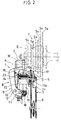
- each of the pins 11, 12, 15, 16 is inclined so that its forward end is located laterally outwardly from its rearward end (see also Fig. 2).
- the movable member 17 also translates forwardly downward (see Fig. 5).
- the inclination angle of the pins 11, 12, 15, 16 may be 30 degrees for example.
- the inner link 13 is always biased laterally outward by a return spring 18 mounted on the pin 11.
- the return spring 18 acts to return the movable member 17 to its laterally outermost position.
- a double-type control cable W which extends along suitable portions (not shown) of the bicycle frame for connection to a shift lever assembly (not shown) at the handlebar or downtube, is connected to the pantograph linkage assembly (see Fig. 1).
- the control cable W includes an inner wire W1 and an outer sheath W2 enclosing the inner wire.
- the base member 10 is provided with a sheath catch 20 for attachment to the outer sheath W2, whereas the inner link 13 is provided with an actuating arm 19 connected to the inner wire W1 extending out of the outer sheath W2.
- a relative longitudinal movement between the inner wire W1 and the outer sheath W2 causes a deformation of the pantograph linkage assembly 9 for shifting the chain C (Fig. 1). Specifically, if the inner cable W1 is pulled in the direction of an arrow p, the pantograph linkage assembly 9 is deformed against the return spring 18 so that the movable member 17 translates laterally inward for shifting the chain C from a diametrically smaller sprocket (S2 in Fig. 1 for example) to a diametrically larger sprocket (S6 in Fig. 5 for example).
- the movable member 17 has an integral forward extension 17a for carrying a second pivot shaft 21 in parallel to the hub shaft 2.
- the upper end of the chain guide 7 is pivotally connected to the second pivot shaft 21.
- a coil spring 23 housed in a spring box 22 is fitted around the second pivot shaft 21 to urge the chain guide 7 in a chain tensioning direction which is clockwise in Fig. 1.
- the second pivot shaft 21 works also as a support shaft for the guide wheel 5.
- the pivotal axis for the chain guide 7 coincides with the rotary axis for the guide wheel 5.
- the chain guide of this type is called a "pendulum type" chain guide and preferred because the movement path of the guide wheel 5 exactly follows that of the movable member 17 to facilitate designing of the rear derailleur for realizing a desired speed change performance.
- the second pivot shaft 21 may be made to pivotally support the chain guide 7 at a portion thereof between the two wheels 5, 6.
- the second pivot shaft 21 may be positioned on a line connecting between the two wheels 5, 6 (as in a "linear leverage type chain guide") or offset from such a line (as in a "triangular leverage type chain guide").
- the interval between the two wheels 5, 6 of the chain guide 7 may be selected depending on the desired gear capacity of the rear derailleur 1; that is, the range or scope of multiple freewheels to which the derailleur 1 may be applied. In general, a larger interval between the two wheels 5, 6 will provide a greater gear capacity.
- the endless chain C in engagement with an unillutrated chainwheel extends rearward for engagement with a rear portion of the tension wheel 6, and then upward for engagement with a front portion of the guide wheel 5 before coming into engagement with a selected sprocket of the freewheel.
- the chain C takes a reversed S-form at the chain guide 7.
- the bicycle rear derailleur 1 having the above-described structure functions in the following manner.
- a portion of the tensioned chain C extending between the guide wheel 5 and the selected sprocket (e.g. S2 in Fig. 1 or S6 in Fig. 5) generates a downward moment which tends to pivot the entirety of the derailleur downward about the first pivot shaft 4.
- the weight of the derailleur 1 itself also generates a downward moment which tends to pivot the entirety of the derailleur 1 downward about the first pivot shaft 4.
- the guide wheel 5 of the chain guide 7 assumes a position where the downward moment (resulting from the chain tension and the gravity) balances with the upward moment.
- the uppermost edge of the guide wheel 5 is located forwardly from and above the lowermost edge of the selected sprocket (e.g. S2 in Fig. 1 or S6 in Fig. 5), so that the chain C leaving the guide wheel 5 extends rearwardly downward before engaging the selected sprocket.
- the base member 10 (namely, the rear derailleur 1 as a whole) is freely pivotable about the first pivot shaft 4 without any spring bias.
- Such free pivotal movement, under no spring-bias, of the base member 10 is advantageous at least for the following reasons.
- the free pivotal movement of the derailleur 1 as a whole allows the guide wheel 5 to always assume an optimum position adjacent to and adhead of the selected sprocket.
- the basic idea underlying here is to let the guide wheel 5 freely move as it needs for assuming the optimum position. If the base member 10 is pivotally biased rearwardly by a spring (as disclosed in U.S. Patent No. 4,610,644), the spring bias will hinder the free movability which is required for the guide wheel 5 to find out its optimum shifting position.
- the free pivotal movement of the derailleur 1 as a whole allows the guide wheel 5 to smoothly move radially of the freewheel F at the time of shifting the chain C.
- the chain C moves not only axially of the freewheel F (namely, axially of the hub shaft 2) but also radially of the freewheel F for disengaging from a current sprocket and engaging a target sprocket
- the guide wheel 5 must also move radially of the freewheel F for following such chain movements.
- the free pivotal movability of the derailleur 1 allows such radial movements of the guide wheel 5.
- a pivotal spring bias for the base member 10 if applied as in U.S. Patent No. 4,610,644) will hinder the guide wheel 5 from smoothly moving radially of the freewheel F.
- the rear derailleur 1 incorporating only the single spring 23 can be rendered applicable to a wide range of freewheels without re-adjustment of spring force.
- the pantograph linkage assembly 9 of the rear derailleur 1 functions to move the chain guide 7 forwardly downward as it moves inward axially of the hub shaft 2.
- the pantograph linkage assembly 9 of this type is advantageous at least for the following reasons.
- the guide wheel 5 of the chain guide 7 can be made to move generally along a common radial line extending from the hub shaft 4 which is located at the center of the freewheel F. Therefore, the guide wheel 5 can take a similar relative position with respect to any sprocket S1-S6 of the freewheel F regardless of the number of sprockets incorporated in the freewheel F. As a result, the rear derailleur 1 can easily adapt to a wide range of freewheels.
- the present invention is described on the basis of the preferred embodiment, it is obvious that the same is not limited to that specific embodiment.
- the present invention is applicable to a rear derailleur of the type disclosed in International Patent Publication No. WO92/10395 (corresponding to U.S. Patent No. 5,238,458) or No. WO93/18958 wherein a parallelogrammic pantograph linkage assembly is mounted on a chain stay in front of a freewheel for moving a chain guide forwardly downward as the chain guide moves inward axially of a hub shaft.
- the pantograph linkage assembly disclosed in International Patent Publication No. 93/18958 incorporates a base member which is made to pivot forwardly downward about a pivot shaft against a spring bias, but such a spring bias need be omitted according to the present invention.
- the present invention is also applicable to a rear derailleur of the type disclosed in U.S. Patent No. 4,610,644.
- a modification need be made to ensure that the guide wheel of the chain guide is always located ahead of the lowermost edge portion of each freewheel sprocket.
- modification include pivotally mounting the base member to a forward extension of a rear fork end, elongating the inner and outer links, and mounting the chain guide to a forward extension of the movable member of the pantograph linkage assembly.
- the pivoting of the base member 10 namely, the rear derailleur 1 as a whole
- the base member 10 may be prevented from pivoting forwardly upward to a position where the chain guide 7 contacts the chain stay.
- the base member 10 may be pivotally biased clockwise by a very weak spring mounted on the first pivot shaft 4.
- a very weak spring mounted on the first pivot shaft 4.
- the purpose of such a weak spring resides not in positively imparting a chain tension (as disclosed in U.S. Patent No. 4,610,644) but only in ensuring that the derailleur 1 as a whole is pivotally moved rearward for facilitating chain removal at the time of replacing the rear wheel. Therefore, the spring for pivotally urging the base member 10 may have a much smaller spring constant than the coil spring 23 mounted on the second pivot shaft 21.
Landscapes
- Engineering & Computer Science (AREA)
- Chemical & Material Sciences (AREA)
- Combustion & Propulsion (AREA)
- Transportation (AREA)
- Mechanical Engineering (AREA)
- Devices For Conveying Motion By Means Of Endless Flexible Members (AREA)
- Transmissions By Endless Flexible Members (AREA)
Description
- The present invention relates to bicycle rear derailleurs for shifting a chain from one sprocket to another of a multiple freewheel according to the preambles of
claim 1 and 6. - Such derailleurs are known from FR-A-2543639.
- As is well known, a bicycle rear derailleur is provided adjacent to a freewheel for shifting a chain from one sprocket to another sprocket of the freewheel. A typical prior art rear derailleur is disclosed in U.S. Patent No. 4,610,644 for example.
- Specifically, the prior art derailleur of the above U.S. patent comprises a chain guide and a pantograph linkage assembly for moving the chain guide axially of the rear hub shaft on which the multiple freewheel is rotatably mounted. The chain guide rotatably supports an upper guide wheel and a lower tension wheel. The pantograph linkage assembly comprises a base member pivotally mounted to a rear fork end of the bicycle frame by a first pivot shaft, inner and outer links having their respective base ends pivotally connected to the base member by first and second pins, and a movable member pivotally connected to the respective free ends of the inner and outer links by third and fourth pins. The movable member pivotally supports the chain guide by a second pivot shaft. The first to fourth pins are located at the four corners of a parallelogram.
- The base member of the pantograph linkage assembly is pivotally biased rearward by a first coil spring mounted on the first pivot shaft. Similarly, the chain guide is pivotally biased rearward by a second coil spring mounted on the second pivot shaft. Thus, the chain in engagement with the guide and tension wheels of the chain guide is tensioned by the first and second coil springs. The derailleur incorporating the two chain tensioning springs is said to have a double-tension mechanism.
- Further, each of the first to fourth pins of the pantograph linkage assembly is inclined so that its lower end is located laterally outwardly from its inner end. As a result, when the pantograph linkage assembly is deformed to move the chain guide laterally inward, the chain guide also moves downwardly. Due to the inclination or slanting of the pins, the pantograph linkage assembly is referred to as a "slant pantograph linkage assembly".
- The prior art derailleur having the slant pantograph linkage assembly and the double tension mechanism has been found to work well with respect to a certain range of freewheels if the first and second coil springs are properly adjusted in their respective spring force. However, the prior art derailleur is still disadvantageous in the following points.
- Since the sprockets of the freewheel diametrically increase inward axially of the hub shaft (i.e., the freewheel), the guide wheel of the chain guide need to move downward as it moves inward axially of the hub shaft. On the other hand, the chain tension progressively increases as the chain shifts to a diametrically larger sprocket of the freewheel, so that the chain tension tends to pivotally move the entirety of the derailleur (including the guide wheel) upward about the first pivot shaft against the first coil spring. Thus, due to the increasing chain tension, the guide wheel may actually move upward toward a diametrically larger sprocket despite the fact that the slant pantograph mechanism itself tends to move the guide wheel downward toward a diametrically larger sprocket of the freewheel. As a result, the prior art derailleur may fail to properly shift the chain from a smaller sprocket to a larger sprocket. This disadvantage will be particularly remarkable when a diametrical difference between the largest and smallest sprockets is large.
- The above disadvantage itself may be overcome by increasing the elastic force of the first coil spring. However, this solution gives rise to a new disadvantage that the guide wheel becomes excessively far from a diametrically smaller sprocket (due to forcible rearward pivoting of the base member under the strong elastic force of the first coil spring) when the chain shifts thereto from a diametrically larger sprocket. Further, if the first coil spring is made to have an increased elastic force, the chain tension will inevitably increase, consequently hindering smooth shifting of the chain.
- Moreover, the double tension mechanism is also disadvantageous in that the elastic forces of the two coil springs must be adjusted in relation to each other for providing a good chain shifting performance with respect to every particular freewheel.
- Another bicycle rear derailleur is disclosed in French patent application 2 543 639 A1.
- In case of the above derailleur which is considered as the most relevant state of the art, the control mechanism is freely pivotable about the first pivot shaft without any spring bias.
- However, it has been found that this derailleur may fail to properly shift the chain in case of a freewheel comprising a plurality of sprockets which diameter increase inward rapidly.
- It is, therefore, an object of the present invention to provide a bicycle rear derailleur which is capable of additionally improving the chain shifting performance.
- According to the present invention, this is achieved by the features of the caracterising portion of
claim 1 and 6 respectivelly. - Preferably, the uppermost edge portion of the guide wheel is located above the lowermost edge portion of said each sprokket which the chain engages. In this case, a portion of the chain leaving the guide wheel for engagement with said each sprocket extends rearwardly downward.
- It is further advantageous if each of the first to fourth pins has a forward end and a rearward end, wherein said each of the first to fourth pins is inclined so that the forward end is located laterally outwardly from the rearward end, whereby when the pantograph linkage assembly is deformed to move the chain guide inward axially of the hub shaft, the chain guide also moves forwardly downward. It is also advantageous if the guide wheel of the chain guide is supported to rotate about the second pivot shaft.
- According to another aspect of the present invention, there is provided a bicycle rear derailleur for shifting a chain from one sprocket to another of a multiple freewheel which includes a plurality of sprockets, the sprockets diametrically increasing inward axially of a hub shaft, the derailleur comprising: a pantograph linkage assembly including a base member pivotally connected to a bicycle frame by a first pivot shaft, inner and outer links having respective base ends pivotally connected to the base member by first and second pins, and a movable member pivotally connected to respective free ends of the inner and outer links by third and fourth pins, the first to fourth pins being located at four corners of a parallelogram; and a chain guide pivotally mounted to the movable member of the pantograph linkage assembly by a second pivot shaft which is parallel to the hub shaft, the chain guide rotataby supporting an upper guide wheel and a lower tension wheel, the chain guide being biased in a chain tensioning direction by a spring; wherein the base member has an upper end pivotally connected to the first pivot shaft and extends downwardly to provide a lower end below the freewheel, the base ends of the inner and outer links being pivotally connected to the lower end of the base member by the first and second pins, the inner and outer links extending upward from the lower end of the base member; characterized that each of the first to fourth pins has a forward end and a rearward end, said each of the first to fourth pins being inclined so that the forward end is located laterally outwardly from the rearward end; whereby when the pantograph linkage assembly is deformed to move the chain guide inward axially of the hub shaft, the chain guide also moves forwardly downward.
- Typically, the first pivot shaft may be mounted on a rear fork end of the bicycle frame. Further, first pivot shaft may be mounted on the rear fork end of the bicycle frame by a mount bracket extending downwardly from the rear fork end.
- Other object, features and advantages of the present invention will become apparent from the following detailed description of the preferred embodiment made with reference to the accompanying drawings.
- In the accompanying drawings:
- Fig. 1 is a side view showing a bicycle rear derailleur according to a preferred embodiment of the present invention when a chain is held in engagement with a smaller sprocket;
- Fig. 2 is a view, partly in section, showing the same derailleur as seen in the direction of an arrow II in Fig. 1;
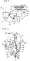
- Fig. 3 is a view of the same derailleur as seen in the direction of an arrow III in Fig. 1;
- Fig. 4 is a view of the same derailleur as seen in the direction of an arrow IV in Fig. 3; and
- Fig. 5 is a side view similar to Fig. 1 but showing the same derailleur when the chain is held in engagement with a larger sprocket.
-
- Referring first to Figs. 1 and 2 of the accompanying drawings there is illustrated a bicycle rear derailleur 1 as mounted to a rear fork end (right-side rear fork end) E of a bicycle frame. The fork end E supports a hub shaft 2 which, in turn, rotatably supports a multiple freewheel F. The freewheel F comprises a plurality of sprockets S1-S6 which diametrically increase inward axially of the hub shaft 2. When operated for a speed change, the rear derailleur 1 functions to shift a chain C from one sprocket to another of the freewheel F.
- A
mount bracket 3 extending rearwardly downward is fixed to the rear fork end E and fixedly carries afirst pivot shaft 4 in parallel to the hub shaft 2. The rear derailleur 1 is mounted to themount bracket 3 for pivotal movement about thefirst pivot shaft 4. In the illustrated embodiment, themount bracket 3 is used to support thefirst pivot shaft 4 in a position slightly below and behind the hub shaft 2. Alternatively, the fork end E itself may have an integral extension extending rearwardly downward to support thefirst pivot shaft 4 in a similar position. - The rear derailleur 1 comprises a chain guide 7 and a
control mechanism 8 for moving the chain guide 7 axially of the hub shaft 2. The chain guide 7 rotatably supports an upper guide wheel (jockey wheel) 5 and alower tension wheel 6. - According to the illustrated embodiment, the
control mechanism 8 comprises apantograph linkage assembly 9 of the bottom pivotal type. Specifically, thepantograph linkage assembly 9 includes abase member 10 having an upper end pivotally connected to thefirst pivot shaft 4 and extending downwardly therefrom, upwardly extending inner andouter links base member 10 byrespective pins movable member 17 pivotally connected to the respective upper ends of the inner andouter links respective pins base member 10 is under no spring-biase relative to thefirst pivot shaft 4, so that thebase member 10 is freely pivotable about thefirst pivot shaft 4. - The
pins elements pantograph linkage assembly 9 is deformed, themovable member 17 translates axially of the hub shaft 4 (i.e., widthwise of the bicycle) while also moving up and down. - As better shown in Fig. 3, each of the
pins pantograph linkage assembly 9 is deformed to move themovable member 17 inwardly widthwise of the bicycle, themovable member 17 also translates forwardly downward (see Fig. 5). The inclination angle of thepins - As shown in Fig. 2, the
inner link 13 is always biased laterally outward by areturn spring 18 mounted on thepin 11. Thus, thereturn spring 18 acts to return themovable member 17 to its laterally outermost position. - A double-type control cable W, which extends along suitable portions (not shown) of the bicycle frame for connection to a shift lever assembly (not shown) at the handlebar or downtube, is connected to the pantograph linkage assembly (see Fig. 1). Specifically, the control cable W includes an inner wire W1 and an outer sheath W2 enclosing the inner wire. As shown in Fig. 4, the
base member 10 is provided with asheath catch 20 for attachment to the outer sheath W2, whereas theinner link 13 is provided with anactuating arm 19 connected to the inner wire W1 extending out of the outer sheath W2. - A relative longitudinal movement between the inner wire W1 and the outer sheath W2 causes a deformation of the
pantograph linkage assembly 9 for shifting the chain C (Fig. 1). Specifically, if the inner cable W1 is pulled in the direction of an arrow p, thepantograph linkage assembly 9 is deformed against thereturn spring 18 so that themovable member 17 translates laterally inward for shifting the chain C from a diametrically smaller sprocket (S2 in Fig. 1 for example) to a diametrically larger sprocket (S6 in Fig. 5 for example). Conversely, when the inner cable W1 is paid out in the direction of an arrow q, thepantograph linkage assembly 9 is deformed by the action of thereturn spring 18 so that themovable member 17 translates laterally outward for shifting the chain C from a diametrically larger sprocket (e.g. S6 in Fig. 5) to a diametrically smaller sprocket (e.g. S2 in Fig. 1). In either case, the chain guide 7 moves with themovable member 17 axially of the hub shaft 2. It should be appreciated that, due to the upward orientation of the inner andouter links - As shown in Figs. 2-4, the
movable member 17 has an integralforward extension 17a for carrying asecond pivot shaft 21 in parallel to the hub shaft 2. The upper end of the chain guide 7 is pivotally connected to thesecond pivot shaft 21. Further, acoil spring 23 housed in aspring box 22 is fitted around thesecond pivot shaft 21 to urge the chain guide 7 in a chain tensioning direction which is clockwise in Fig. 1. - According to the illustrated embodiment, the
second pivot shaft 21 works also as a support shaft for theguide wheel 5. Thus, the pivotal axis for the chain guide 7 coincides with the rotary axis for theguide wheel 5. The chain guide of this type is called a "pendulum type" chain guide and preferred because the movement path of theguide wheel 5 exactly follows that of themovable member 17 to facilitate designing of the rear derailleur for realizing a desired speed change performance. - Alternatively, the
second pivot shaft 21 may be made to pivotally support the chain guide 7 at a portion thereof between the twowheels second pivot shaft 21 may be positioned on a line connecting between the twowheels 5, 6 (as in a "linear leverage type chain guide") or offset from such a line (as in a "triangular leverage type chain guide"). - The interval between the two
wheels wheels - As shown in Figs. 1 and 5, the endless chain C in engagement with an unillutrated chainwheel (front gear) extends rearward for engagement with a rear portion of the
tension wheel 6, and then upward for engagement with a front portion of theguide wheel 5 before coming into engagement with a selected sprocket of the freewheel. Thus, the chain C takes a reversed S-form at the chain guide 7. - The bicycle rear derailleur 1 having the above-described structure functions in the following manner.
- Since the chain guide 7 pivotally supported on the
second pivot shaft 21 is elastically urged rearward (clockwise in Figs. 1 and 5) by thecoil spring 23, thetension wheel 6 applies a tension to the chain C. However, since the length of the chain C is always constant, a portion of the tensioned chain C extending toward thetension pulley 6 generates an upward moment which tends to pivot the entirety of the derailleur 1 upward about thefirst pivot shaft 4. Due to this upward moment, theguide wheel 5 of the chain guide 7 tends to pivotally move upward about thefirst pivot shaft 4, thereby acting to wind the chain C around a selected sprocket (e.g. S2 in Fig. 1 or S6 in Fig. 5) which the chain C currently engages. - On the other hand, a portion of the tensioned chain C extending between the
guide wheel 5 and the selected sprocket (e.g. S2 in Fig. 1 or S6 in Fig. 5) generates a downward moment which tends to pivot the entirety of the derailleur downward about thefirst pivot shaft 4. Further, the weight of the derailleur 1 itself also generates a downward moment which tends to pivot the entirety of the derailleur 1 downward about thefirst pivot shaft 4. - As a result, the
guide wheel 5 of the chain guide 7 assumes a position where the downward moment (resulting from the chain tension and the gravity) balances with the upward moment. In such a balancing position, the uppermost edge of theguide wheel 5 is located forwardly from and above the lowermost edge of the selected sprocket (e.g. S2 in Fig. 1 or S6 in Fig. 5), so that the chain C leaving theguide wheel 5 extends rearwardly downward before engaging the selected sprocket. - As previously described, the base member 10 (namely, the rear derailleur 1 as a whole) is freely pivotable about the
first pivot shaft 4 without any spring bias. Such free pivotal movement, under no spring-bias, of thebase member 10 is advantageous at least for the following reasons. - First, whichever sprocket of the freewheel F is selected by the rear derailleur 1 for engagement with the chain C, the free pivotal movement of the derailleur 1 as a whole allows the
guide wheel 5 to always assume an optimum position adjacent to and adhead of the selected sprocket. The basic idea underlying here is to let theguide wheel 5 freely move as it needs for assuming the optimum position. If thebase member 10 is pivotally biased rearwardly by a spring (as disclosed in U.S. Patent No. 4,610,644), the spring bias will hinder the free movability which is required for theguide wheel 5 to find out its optimum shifting position. - Secondly, the free pivotal movement of the derailleur 1 as a whole allows the
guide wheel 5 to smoothly move radially of the freewheel F at the time of shifting the chain C. Specifically, since the chain C moves not only axially of the freewheel F (namely, axially of the hub shaft 2) but also radially of the freewheel F for disengaging from a current sprocket and engaging a target sprocket, theguide wheel 5 must also move radially of the freewheel F for following such chain movements. The free pivotal movability of the derailleur 1 allows such radial movements of theguide wheel 5. Apparently, a pivotal spring bias for the base member 10 (if applied as in U.S. Patent No. 4,610,644) will hinder theguide wheel 5 from smoothly moving radially of the freewheel F. - In the third place, since the
base member 10 is free from any pivotal spring bias with the chain tension applied solely by thecoil spring 23 on thesecond pivot shaft 21, there is no need for making adjustment between two springs. Thus, the rear derailleur 1 incorporating only thesingle spring 23 can be rendered applicable to a wide range of freewheels without re-adjustment of spring force. - In the fourth place, since the chain tension is applied solely by the
single coil spring 23 on the second pivot shat 21, the magnitude of the chain tension can be kept relatively small to improve the shiftability of the chain C. If thebase member 10 is pivotally biased rearward by a second spring mounted on the first pivot shaft 4 (as disclosed in U.S. Patent No. 4,610,644), the chain tension will increase due to a distortion of the second spring, consequently hindering smooth shifting of the chain C. Such a disadvantage can be avoided by making thebase member 10 freely pivotable about thefirst pivot shaft 4. - Apparently, all of the advantages described above contribute to improving the chain shifting performance or ability of the rear derailleur 1.
- According to the illustrated embodiment, the
pantograph linkage assembly 9 of the rear derailleur 1 functions to move the chain guide 7 forwardly downward as it moves inward axially of the hub shaft 2. Thepantograph linkage assembly 9 of this type is advantageous at least for the following reasons. - First, the
guide wheel 5 of the chain guide 7 can be made to move generally along a common radial line extending from thehub shaft 4 which is located at the center of the freewheel F. Therefore, theguide wheel 5 can take a similar relative position with respect to any sprocket S1-S6 of the freewheel F regardless of the number of sprockets incorporated in the freewheel F. As a result, the rear derailleur 1 can easily adapt to a wide range of freewheels. - Secondly, since the chain guide 7 moves forwardly as it moves laterally toward a diametrically larger sprocket of the freewheel F, the degree of distortion of the coil spring 23 (Fig. 2) can be minimized (see Figs. 1 and 5) when the chain C is shifted to the diametrically larger sprocket. As a result, an increase of the chain tension is kept as small as possible to improve the chain shifting performance. If the chain guide 7 is made to move rearwardly downward (as disclosed in U.S. Patent No. 4,610,644), the
coil spring 23 must be distorted to a much greater degree than illustrated in Fig. 5 because the chain C has a constant length. - While the present invention is described on the basis of the preferred embodiment, it is obvious that the same is not limited to that specific embodiment. For instance, the present invention is applicable to a rear derailleur of the type disclosed in International Patent Publication No. WO92/10395 (corresponding to U.S. Patent No. 5,238,458) or No. WO93/18958 wherein a parallelogrammic pantograph linkage assembly is mounted on a chain stay in front of a freewheel for moving a chain guide forwardly downward as the chain guide moves inward axially of a hub shaft. It should be appreciated that the pantograph linkage assembly disclosed in International Patent Publication No. 93/18958 incorporates a base member which is made to pivot forwardly downward about a pivot shaft against a spring bias, but such a spring bias need be omitted according to the present invention.
- Further, the present invention is also applicable to a rear derailleur of the type disclosed in U.S. Patent No. 4,610,644. In this case, however, a modification need be made to ensure that the guide wheel of the chain guide is always located ahead of the lowermost edge portion of each freewheel sprocket. Examples of modification include pivotally mounting the base member to a forward extension of a rear fork end, elongating the inner and outer links, and mounting the chain guide to a forward extension of the movable member of the pantograph linkage assembly.
- Further, the pivoting of the base member 10 (namely, the rear derailleur 1 as a whole) about the
first pivot shaft 4 may be limited within a predetermined range. For example, thebase member 10 may be prevented from pivoting forwardly upward to a position where the chain guide 7 contacts the chain stay. - Moreover, the
base member 10 may be pivotally biased clockwise by a very weak spring mounted on thefirst pivot shaft 4. The purpose of such a weak spring resides not in positively imparting a chain tension (as disclosed in U.S. Patent No. 4,610,644) but only in ensuring that the derailleur 1 as a whole is pivotally moved rearward for facilitating chain removal at the time of replacing the rear wheel. Therefore, the spring for pivotally urging thebase member 10 may have a much smaller spring constant than thecoil spring 23 mounted on thesecond pivot shaft 21. - The modifications described above are not to be regarded as a departure from the spirit and scope of the present invention, and all such modifications as would be obvious to those skilled in the art are intended to be covered by the appended claims.
Claims (10)
- A bicycle rear derailleur (1) for shifting a chain (C) from one sprocket to another of a multiple freewheel (F) which includes a plurality of sprockets (S1-S6), the sprockets diametrically increasing inward axially of a hub shaft (2), each of the sprockets (S1-S6) having a lowermost edge portion, the derailleur (1) comprising: a control mechanism (8) pivotally mounted to a bicycle frame (E) by a first pivot shaft (4) which is parallel to the hub shaft (2); and a chain guide (7) pivotally mounted to the control mechanism (8) by a second pivot shaft (21) which is parallel to the hub shaft (2), the chain guide (7) rotataby supporting an upper guide wheel (5) and a lower tension wheel (6), the chain guide (7) being biased in a chain tensioning direction by a spring (23), the chain guide (7) being controlled by the control mechanism (8) to move axially of the hub shaft (2), the guide wheel (5) having an uppermost edge portion located ahead of the lowermost edge portion of each sprocket (S1-S6) which the chain (C) engages;the control mechanism (8) being freely pivotable about the first pivot shaft (4) without any spring bias at least within a predetermined range, whereby the control mechanism (8) comprises a pantograph linkage assembly (9) which includes: a base member (10) having an upper end pivotally connected to the first pivot shaft (4) and extending downwardly to provide a lower end below the freewheel (F), inner and outer links (13, 14) having respective base ends pivotally connected to the lower end of the base member (10) by first and second pins (11, 12) the inner and outer links (13, 14) extending from the lower end of the base member (10); and a movable member (17) pivotally connected to respective free ends of the inner and outer links (13, 14) by third and fourth pins (15, 16), the movable member (17) carrying the second pivot shaft (21); the first to fourth pins (11, 12, 15, 16) being located at four corners of a parallelogram characterized in that the inner and outer links (13, 14) extend upwardly from the base member (10) such that when the pantograph linkage assembly (9) is deformed to move the chain guide (7) inward axially of the hub shaft (2), the pantograph linkage assembly (9) functions to move the chain guide (7) forwardly downward.
- The derailleur according to claim 1, wherein the uppermost edge portion of the guide wheel (5) is located above the lowermost edge portion of said each sprocket (S1-S6) which the chain (C) engages.
- The derailleur according to claim 1 or 2, wherein the first pivot shaft (4) is mounted on a rear fork end of the bicycle frame.
- The derailleur according to anyone of the claims 1 to 3, wherein each of the first to fourth pins (11, 12, 15, 16) has a forward end and a rearward end, said each of the first to fourth pins (11, 12, 15, 16) being inclined so that the forward end is located laterally outwardly from the rearward end, whereby when the pantograph linkage assembly (9) is deformed to move the chain guide (7) inward axially of the hub shaft (2), the chain guide (7) also moves forwardly downward.
- The derailleur according to any one of claims 1 to 4, wherein the guide wheel (5) of the chain guide (7) is supported to rotate about the second pivot shaft (21).
- A bicycle rear derailleur (1) for shifting a chain (C) from one sprocket to another of a multiple freewheel (F) which includes a plurality of sprockets (S1-S6), the sprockets diametrically increasing inward axially of a hub shaft (2), the derailleur (1) comprising: a pantograph linkage assembly (9) including a base member (10) pivotally connected to a bicycle frame (E) by a first pivot shaft, inner and outer links (13, 14) having respective base ends pivotally connected to the base member (10) by first and second pins (11, 12), and a movable member (17) pivotally connected to respective free ends of the inner and outer links (13, 14) by third and fourth pins (15, 16), the first to fourth pins (11, 12, 15, 16) being located at four corners of a parallelogram; and a chain guide (7) pivotally mounted to the movable member (17) of the pantograph linkage assembly (9) by a second pivot shaft (21) which is parallel to the hub shaft (2), the chain guide (7) rotataby supporting an upper guide wheel (5) and a lower tension wheel (6), the chain guide (7) being biased in a chain tensioning direction by a spring (23);
whereby the base member (10) has an upper end pivotally connected to the first pivot shaft (4) and extends downwardly to provide a lower end below the freewheel (F), the base ends of the inner and outer links (13, 14) being pivotally connected to the lower end of the base member (10) by the first and second pins (11, 12), the inner and outer links (13, 14) extending from the lower end of the base member (10); characterized in that the inner and outer links (13, 14) extend upwardly from the base member (10);that each of the first to fourth pins (11, 12, 15, 16) has a forward end and a rearward end, said each of the first to fourth pins (11, 12, 15, 16) being inclined so that the forward end is located laterally outwardly from the rearward end;
whereby when the pantograph linkage assembly (9) is deformed to move the chain guide (7) inward axially of the hub shaft (2), the chain guide (7) also moves forwardly downward. - The derailleur according to claim 6, wherein the guide wheel (5) has an uppermost edge portion which is located forwardly from and above a lowermost edge portion of each sprocket (S1-S6) in engagement with the chain (C).
- The derailleur according to claim 6 or 7, wherein the first pivot shaft (4) is mounted on a rear fork end (E) of the bicycle frame.
- The derailleur according to claim 8, wherein the first pivot shaft (4) is mounted on the rear fork end (E) of the bicycle frame by a mount bracket (3) extending downwardly from the rear fork end (E).
- The derailleur according to any one of claims 6 to 9, wherein the guide wheel (5) of the chain guide (7) is supported to rotate about the second pivot shaft (21).
Applications Claiming Priority (2)
| Application Number | Priority Date | Filing Date | Title |
|---|---|---|---|
| JP343775/93 | 1993-12-06 | ||
| JP5343775A JPH07156855A (en) | 1993-12-06 | 1993-12-06 | Rear derailer for bicycle and installing structure thereof |
Publications (3)
| Publication Number | Publication Date |
|---|---|
| EP0657346A2 EP0657346A2 (en) | 1995-06-14 |
| EP0657346A3 EP0657346A3 (en) | 1995-07-26 |
| EP0657346B1 true EP0657346B1 (en) | 1999-03-10 |
Family
ID=18364147
Family Applications (1)
| Application Number | Title | Priority Date | Filing Date |
|---|---|---|---|
| EP94119233A Expired - Lifetime EP0657346B1 (en) | 1993-12-06 | 1994-12-06 | Bicycle rear derailleur |
Country Status (5)
| Country | Link |
|---|---|
| US (1) | US5597366A (en) |
| EP (1) | EP0657346B1 (en) |
| JP (1) | JPH07156855A (en) |
| CN (1) | CN1056577C (en) |
| DE (1) | DE69416956T2 (en) |
Families Citing this family (37)
| Publication number | Priority date | Publication date | Assignee | Title |
|---|---|---|---|---|
| US5860880A (en) * | 1996-11-21 | 1999-01-19 | Shimano, Inc. | Low normal bicycle derailleur which allows lateral movement of the chain guide toward the rear wheel in response to a force directed laterally towards the rear wheel |
| US5919106A (en) * | 1997-04-30 | 1999-07-06 | Shimano, Inc. | Quick release derailleur |
| USD406084S (en) * | 1997-07-23 | 1999-02-23 | Shimano Inc. | Rear derailleur pulley set |
| US6203459B1 (en) * | 1997-07-25 | 2001-03-20 | John L. Calendrille, Jr. | Bicycle derailleur system with integral flexible seal to protect moving parts from contaminants |
| US6293883B1 (en) | 1998-09-10 | 2001-09-25 | Shimano, Inc. | Quick release derailleur |
| USD432056S (en) * | 1999-04-07 | 2000-10-17 | Shimano, Inc. | Bicycle rear derailleur |
| ITTO20001124A1 (en) * | 2000-12-01 | 2002-06-01 | Campagnolo Srl | ROCKER GROUP FOR THE REAR DERAILLEUR OF A BICYCLE. |
| US20030171176A1 (en) * | 2002-03-07 | 2003-09-11 | Shimano, Inc. | Bicycle rear derailleur |
| CN1329241C (en) * | 2002-03-08 | 2007-08-01 | 株式会社岛野 | Rear chain-moving device for bicycle |
| JP3746025B2 (en) | 2002-07-31 | 2006-02-15 | 株式会社シマノ | Bicycle rear derailleur |
| JP2005238979A (en) * | 2004-02-26 | 2005-09-08 | Shimano Inc | Rear derailleur for bicycle |
| EP1799534B1 (en) | 2004-09-15 | 2014-08-27 | Yeti Cycling LLC | Rear suspension system for a bicycle |
| US20070021246A1 (en) * | 2005-07-19 | 2007-01-25 | Shimano Inc. | Bicycle rear derailleur |
| US8277346B2 (en) * | 2006-02-28 | 2012-10-02 | Shimano, Inc. | Low profile rear derailleur |
| US20070202978A1 (en) * | 2006-02-28 | 2007-08-30 | Shimano, Inc. | Low profile rear derailleur |
| US8012052B2 (en) * | 2006-02-28 | 2011-09-06 | Shimano, Inc. | Low profile rear derailleur with cable guide |
| US8025598B2 (en) * | 2006-10-24 | 2011-09-27 | Shimano, Inc. | Low profile rear derailleur with a chain receiving space |
| JP2008195129A (en) | 2007-02-09 | 2008-08-28 | Shimano Inc | Rear derailleur for bicycle |
| DE102007040156B4 (en) * | 2007-08-24 | 2013-08-29 | Shimano Inc. | Rear bicycle derailleur |
| JP2009056969A (en) * | 2007-08-31 | 2009-03-19 | Shimano Inc | Rear derailleur for bicycle |
| US9821879B2 (en) | 2010-08-20 | 2017-11-21 | Yeti Cycling, Llc | Reciprocating rail movement suspension system |
| US9102378B2 (en) | 2010-08-20 | 2015-08-11 | Yeti Cycling, Llc | Link suspension system |
| US9033833B2 (en) | 2011-01-28 | 2015-05-19 | Paha Designs, Llc | Gear transmission and derailleur system |
| US9327792B2 (en) | 2011-01-28 | 2016-05-03 | Paha Designs, Llc | Gear transmission and derailleur system |
| US10207772B2 (en) | 2011-01-28 | 2019-02-19 | Paha Designs, Llc | Gear transmission and derailleur system |
| US10766563B2 (en) | 2013-01-16 | 2020-09-08 | Yeti Cyclying, Llc | Rail suspension with integral shock and dampening mechanism |
| US10011325B2 (en) | 2014-12-10 | 2018-07-03 | Yeti Cycling, Llc | Linear derailleur mechanism |
| EP3595963A4 (en) | 2017-03-17 | 2021-03-10 | Yeti Cycling, LLC | Vehicle suspension linkage |
| DE102018001253A1 (en) * | 2017-03-20 | 2018-09-20 | Sram Deutschland Gmbh | Rear derailleur for coaxial mounting |
| IT201700035716A1 (en) * | 2017-03-31 | 2018-10-01 | Campagnolo Srl | Bicycle rear derailleur |
| WO2019010394A1 (en) | 2017-07-07 | 2019-01-10 | Yeti Cycling, Llc | Vehicle suspension linkage |
| US10703442B2 (en) * | 2017-07-14 | 2020-07-07 | Shimano Inc. | Bicycle rear derailleur |
| US10501147B2 (en) * | 2017-08-22 | 2019-12-10 | Shimano Inc. | Bicycle derailleur |
| US11319021B2 (en) * | 2017-08-23 | 2022-05-03 | Shimano Inc. | Bicycle rear derailleur |
| TWI647146B (en) * | 2017-11-10 | 2019-01-11 | 台灣微轉股份有限公司 | Bicycle rear derailleur |
| CN107719573B (en) * | 2017-11-20 | 2023-05-05 | 珠海蓝图运动科技股份有限公司 | Bicycle derailleur mounting structure and bicycle |
| DE102020000827A1 (en) * | 2019-04-25 | 2020-10-29 | Sram Deutschland Gmbh | Electromechanical switching mechanism for coaxial assembly |
Family Cites Families (19)
| Publication number | Priority date | Publication date | Assignee | Title |
|---|---|---|---|---|
| US3974707A (en) * | 1974-08-03 | 1976-08-17 | Shimano Industrial Company, Limited | Derailleur for a bicycle |
| US4183255A (en) * | 1974-12-16 | 1980-01-15 | Fichtel & Sachs Ag | Bicycle with derailleur arrangement |
| JPS54138252A (en) * | 1978-04-17 | 1979-10-26 | Shimano Industrial Co | Rear derailer for bicycle |
| JPS593022Y2 (en) * | 1979-05-04 | 1984-01-27 | 株式会社シマノ | bicycle derailleur |
| FR2466388A1 (en) * | 1979-10-05 | 1981-04-10 | Huret Roger | DERAILLEUR FOR CYCLE |
| US4437848A (en) * | 1980-03-15 | 1984-03-20 | Shimano Industrial Company Limited | Derailleur for a bicycle |
| US4610644A (en) * | 1983-02-23 | 1986-09-09 | Shimano Industrial Company Limited | Derailleur for a bicycle |
| FR2543639A1 (en) * | 1983-04-01 | 1984-10-05 | Simplex Ets | Gear change with angular positioning stop for cycles and similar vehicles |
| US4575365A (en) * | 1983-08-02 | 1986-03-11 | Shimano Industrial Company Limited | Rear derailleur for a bicycle |
| JPS60186292U (en) * | 1984-05-21 | 1985-12-10 | 株式会社シマノ | bicycle derailleur |
| JPS6136490U (en) * | 1984-08-08 | 1986-03-06 | 株式会社シマノ | bicycle rear derailleur |
| US4692131A (en) * | 1985-05-20 | 1987-09-08 | Shimano Industrial Company Limited | Rear derailleur for a bicycle |
| JPS6349434Y2 (en) * | 1985-10-24 | 1988-12-19 | ||
| JPS63184589A (en) * | 1987-01-28 | 1988-07-30 | 株式会社シマノ | Derailer for bicycle |
| JPS63215481A (en) * | 1987-02-28 | 1988-09-07 | 株式会社シマノ | Derailer for bicycle |
| US4789379A (en) * | 1987-10-06 | 1988-12-06 | Maeda Industries, Ltd. | Bicycle deraileur |
| US5213549A (en) * | 1991-07-22 | 1993-05-25 | Pierre Blanchard | Derailleurs for multi-speed bicycles |
| JPH0820375A (en) * | 1991-11-11 | 1996-01-23 | Mori San Tour:Kk | Speed change mechanis for bicycle |
| JPH05270474A (en) * | 1992-03-23 | 1993-10-19 | Maeda Kogyo Kk | Rear delayer for bicycle |
-
1993
- 1993-12-06 JP JP5343775A patent/JPH07156855A/en active Pending
-
1994
- 1994-12-06 DE DE69416956T patent/DE69416956T2/en not_active Expired - Fee Related
- 1994-12-06 CN CN94112758A patent/CN1056577C/en not_active Expired - Fee Related
- 1994-12-06 EP EP94119233A patent/EP0657346B1/en not_active Expired - Lifetime
- 1994-12-06 US US08/349,819 patent/US5597366A/en not_active Expired - Fee Related
Also Published As
| Publication number | Publication date |
|---|---|
| US5597366A (en) | 1997-01-28 |
| EP0657346A2 (en) | 1995-06-14 |
| JPH07156855A (en) | 1995-06-20 |
| CN1056577C (en) | 2000-09-20 |
| CN1119610A (en) | 1996-04-03 |
| DE69416956T2 (en) | 1999-11-11 |
| EP0657346A3 (en) | 1995-07-26 |
| DE69416956D1 (en) | 1999-04-15 |
Similar Documents
| Publication | Publication Date | Title |
|---|---|---|
| EP0657346B1 (en) | Bicycle rear derailleur | |
| EP1818254B1 (en) | Bicycle front derailleur | |
| EP1632429B1 (en) | Bicycle rear derailleur | |
| US5460576A (en) | Bicycle chain guide | |
| EP1607320B1 (en) | Variable speed drive device for bicycle | |
| US8057332B2 (en) | Bicycle derailleur | |
| EP0850829B1 (en) | Rear derailleur for a bicycle | |
| EP0757952B1 (en) | Front derailleur for a bicycle | |
| US4637808A (en) | Bicycle rear derailleur | |
| EP0814016B1 (en) | Bicycle front derailleur | |
| EP1582449A2 (en) | Bicycle derailleur | |
| CN101204987B (en) | Bicycle shift operating device | |
| EP2030889B1 (en) | Bicycle rear derailleur | |
| EP1935774B1 (en) | Bicycle rear derailleur | |
| EP1475301A2 (en) | Rear derailleur with cable guide roller | |
| US5397273A (en) | Rear derailleur for a bicycle | |
| EP2331845A1 (en) | Six link front derailleur | |
| EP1955941B1 (en) | Bicycle rear derailleur | |
| US6282976B1 (en) | Discontinuous mechanical advantage front shifting for bicycles | |
| US5533937A (en) | Bicycle derailleur | |
| EP1609715A2 (en) | Front derailleur for a bicycle | |
| GB1564125A (en) | Derailleur for a bicycle | |
| EP0761529B1 (en) | Bicycle with transmission assembly | |
| JP2005238979A (en) | Rear derailleur for bicycle | |
| EP0542077A1 (en) | Bicycle speed change assembly |
Legal Events
| Date | Code | Title | Description |
|---|---|---|---|
| PUAI | Public reference made under article 153(3) epc to a published international application that has entered the european phase |
Free format text: ORIGINAL CODE: 0009012 |
|
| PUAL | Search report despatched |
Free format text: ORIGINAL CODE: 0009013 |
|
| AK | Designated contracting states |
Kind code of ref document: A2 Designated state(s): DE FR GB IT NL |
|
| AK | Designated contracting states |
Kind code of ref document: A3 Designated state(s): DE FR GB IT NL |
|
| 17P | Request for examination filed |
Effective date: 19950715 |
|
| 17Q | First examination report despatched |
Effective date: 19970530 |
|
| GRAG | Despatch of communication of intention to grant |
Free format text: ORIGINAL CODE: EPIDOS AGRA |
|
| GRAG | Despatch of communication of intention to grant |
Free format text: ORIGINAL CODE: EPIDOS AGRA |
|
| GRAH | Despatch of communication of intention to grant a patent |
Free format text: ORIGINAL CODE: EPIDOS IGRA |
|
| RAP1 | Party data changed (applicant data changed or rights of an application transferred) |
Owner name: SUGINO CYCLE INDUSTRIES, LTD. |
|
| RIN1 | Information on inventor provided before grant (corrected) |
Inventor name: OZAKI, NOBUO |
|
| GRAH | Despatch of communication of intention to grant a patent |
Free format text: ORIGINAL CODE: EPIDOS IGRA |
|
| GRAA | (expected) grant |
Free format text: ORIGINAL CODE: 0009210 |
|
| AK | Designated contracting states |
Kind code of ref document: B1 Designated state(s): DE FR GB IT NL |
|
| REF | Corresponds to: |
Ref document number: 69416956 Country of ref document: DE Date of ref document: 19990415 |
|
| ITF | It: translation for a ep patent filed |
Owner name: FIAMMENGHI - DOMENIGHETTI |
|
| ET | Fr: translation filed | ||
| PG25 | Lapsed in a contracting state [announced via postgrant information from national office to epo] |
Ref country code: GB Free format text: LAPSE BECAUSE OF NON-PAYMENT OF DUE FEES Effective date: 19991206 |
|
| PLBE | No opposition filed within time limit |
Free format text: ORIGINAL CODE: 0009261 |
|
| STAA | Information on the status of an ep patent application or granted ep patent |
Free format text: STATUS: NO OPPOSITION FILED WITHIN TIME LIMIT |
|
| 26N | No opposition filed | ||
| PG25 | Lapsed in a contracting state [announced via postgrant information from national office to epo] |
Ref country code: NL Free format text: LAPSE BECAUSE OF NON-PAYMENT OF DUE FEES Effective date: 20000701 |
|
| GBPC | Gb: european patent ceased through non-payment of renewal fee |
Effective date: 19991206 |
|
| NLV4 | Nl: lapsed or anulled due to non-payment of the annual fee |
Effective date: 20000701 |
|
| PGFP | Annual fee paid to national office [announced via postgrant information from national office to epo] |
Ref country code: DE Payment date: 20011208 Year of fee payment: 8 |
|
| PGFP | Annual fee paid to national office [announced via postgrant information from national office to epo] |
Ref country code: FR Payment date: 20011211 Year of fee payment: 8 |
|
| PG25 | Lapsed in a contracting state [announced via postgrant information from national office to epo] |
Ref country code: DE Free format text: LAPSE BECAUSE OF NON-PAYMENT OF DUE FEES Effective date: 20030701 |
|
| PG25 | Lapsed in a contracting state [announced via postgrant information from national office to epo] |
Ref country code: FR Free format text: LAPSE BECAUSE OF NON-PAYMENT OF DUE FEES Effective date: 20030901 |
|
| REG | Reference to a national code |
Ref country code: FR Ref legal event code: ST |
|
| PG25 | Lapsed in a contracting state [announced via postgrant information from national office to epo] |
Ref country code: IT Free format text: LAPSE BECAUSE OF NON-PAYMENT OF DUE FEES;WARNING: LAPSES OF ITALIAN PATENTS WITH EFFECTIVE DATE BEFORE 2007 MAY HAVE OCCURRED AT ANY TIME BEFORE 2007. THE CORRECT EFFECTIVE DATE MAY BE DIFFERENT FROM THE ONE RECORDED. Effective date: 20051206 |