EP0657132A1 - Form und Anordnung der Bauelemente eines Fleischgrillgerätes mit Kunststoffgehäuse - Google Patents
Form und Anordnung der Bauelemente eines Fleischgrillgerätes mit Kunststoffgehäuse Download PDFInfo
- Publication number
- EP0657132A1 EP0657132A1 EP94420350A EP94420350A EP0657132A1 EP 0657132 A1 EP0657132 A1 EP 0657132A1 EP 94420350 A EP94420350 A EP 94420350A EP 94420350 A EP94420350 A EP 94420350A EP 0657132 A1 EP0657132 A1 EP 0657132A1
- Authority
- EP
- European Patent Office
- Prior art keywords
- thermal
- tank
- cooking
- thermal reflector
- reflector
- Prior art date
- Legal status (The legal status is an assumption and is not a legal conclusion. Google has not performed a legal analysis and makes no representation as to the accuracy of the status listed.)
- Granted
Links
Images
Classifications
-
- A—HUMAN NECESSITIES
- A47—FURNITURE; DOMESTIC ARTICLES OR APPLIANCES; COFFEE MILLS; SPICE MILLS; SUCTION CLEANERS IN GENERAL
- A47J—KITCHEN EQUIPMENT; COFFEE MILLS; SPICE MILLS; APPARATUS FOR MAKING BEVERAGES
- A47J37/00—Baking; Roasting; Grilling; Frying
- A47J37/06—Roasters; Grills; Sandwich grills
- A47J37/067—Horizontally disposed broiling griddles
- A47J37/0676—Horizontally disposed broiling griddles electrically heated
-
- A—HUMAN NECESSITIES
- A47—FURNITURE; DOMESTIC ARTICLES OR APPLIANCES; COFFEE MILLS; SPICE MILLS; SUCTION CLEANERS IN GENERAL
- A47J—KITCHEN EQUIPMENT; COFFEE MILLS; SPICE MILLS; APPARATUS FOR MAKING BEVERAGES
- A47J37/00—Baking; Roasting; Grilling; Frying
- A47J37/06—Roasters; Grills; Sandwich grills
- A47J37/0611—Roasters; Grills; Sandwich grills the food being cooked between two heating plates, e.g. waffle-irons
Definitions
- the present invention relates to the use of specific parts and elements for the production of devices of the grill-meat or waffle maker type and to a particular arrangement or mounting of said elements to obtain perfect control of the heat flows.
- the invention applies to the field of grilling devices consisting of a frame for example of non-metallic material and more particularly to the field of devices dissipating a large thermal power such as grill-meat. It is obvious that the invention is not limited to grills and that any appliance intended for cooking food can be concerned with the subject of the present invention.
- the use of a low-cost plastic material for producing the frame of the grill appliance is then possible.
- the broiler presents nevertheless a certain number of disadvantages which cannot satisfy the user.
- the apparatus described in this document uses solutions such as an atmosphere saturated with water vapor and mechanical pressure on the article to be grilled, thereby increasing the design difficulty and the cost of manufacturing such a device.
- the object of the present invention is to provide the user with a grilling appliance comprising a frame, made of plastic material for example, in which the heat fluxes are controlled and used optimally on the one hand and the reduced heat losses d on the other hand, to optimize the firing or successive firing of several articles without having recourse to a cooking atmosphere saturated with water vapor or to materials resistant to very high temperatures.
- Another object of the present invention is to optimize the transfer of heat flow by using materials whose emissivity with respect to infrared radiation is more or less, depending on the arrangement of the constituent parts of the grilling appliance. .
- Another object of the present invention is to facilitate the assembly / disassembly of different parts and in particular the cooking plates of the appliance to be grilled to facilitate their cleaning after one or more cooking phases.
- Another object of the present invention is to facilitate the transfer of thermal energy to the articles to be grilled while reducing the thermal inertia presented by said grilling appliance according to the invention.
- Another object of the present invention is to limit the rise in temperature of said device during cooking, so as to be able to use in particular a low-cost plastic material to produce the frame of the device in accordance to the invention.
- An additional object of the present invention is to reduce the number of parts constituting said device and therefore to reduce the manufacturing cost on the one hand and the manufacturing or construction difficulties on the other.
- a grilling or cooking appliance comprising a frame made of plastic material, at least one removable cooking plate on which the article to be grilled rests, at least one heating element , at least one thermal reflector for reflecting the infrared radiation emitted by the heating element towards the cooking plate, as well as a thermal sensor intended for regulating the temperature of said appliance, characterized in that a metal tank is arranged on the frame for on the one hand supporting the thermal reflector, the cooking plate and the heating element and on the other hand realizing with the thermal reflector and the frame, an interlocking in which the thermal reflector extends into the internal volume defined by the tank, which produces an additional thermal reflector, fixed on the frame using heat-resistant means and establishing punctual mechanical contacts with the hob and with the thermal reflector using respectively flexible connecting pieces and fixing means of the male / female type.
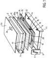
- the grilling appliance comprises a frame, a tank 10, at least one cooking plate 30 as well as a thermal reflector 20.
- the frame has a lower part 1 on which is arranged the cooking plate 30 and an upper part 2 on which is arranged a cooking plate 31, said upper part 2 being foldable on the lower part 1.
- the frame is made of a plastic material based on polypropylene. Other materials, such as metal, may also be suitable.
- the grilling appliance according to the invention consists of two parts which can be folded one on the other by means of a hinge for example or any other pivoting means of the articulation type making it possible to bring the upper part 2 towards the lower part 1.
- the pivoting means is obtained for example by providing a groove 4 in an upright 3 of the lower part 1 and by the arrangement of a rod 5 on the upper part 2, said rod 5 coming to slide in the groove 4
- the groove 4 and the rod 5 are disposed respectively on the lower part 1 and the upper part 2 on either side of what constitutes the rear of the grilling appliance, so as to allow the part to pivot. upper 2 on the lower part 1.
- the groove 4 has sufficient dimensions to give the rod 5 a free stroke in said groove 4.
- the grilling apparatus comprising the upper part 2 folded or closed on the p lower part 1 can be in different positions of closure corresponding to different spacings of the cooking plates 30 and 31.
- This is particularly advantageous when cooking grilling articles of different or uneven thickness.
- the pivoting means of the type of joint used is found on both sides on the lateral sides of the grill appliance.
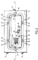
- the tank 10, preferably metallic, is fixed or arranged on the frame by means of spacers 6 made, for example of high temperature technical plastic, or any other material resistant to high temperatures, or refractory.
- the tank 10 shown in FIG. 2 also includes orifices 12 into which the spacers 6 are inserted or fitted during the mounting of the tank 10 in the lower part 1.
- the tank 10 can be secured to the lower part 1 mechanically or chemically by bonding, for example using an adhesive resistant to high temperatures.
- the number of spacers 6 and orifices 12 is at least equal to 3 and preferably equal to 4.
- the fixing points thus produced are distributed over the periphery of the tank 10 and of the lower part 1 so as to obtain a stable positioning of said tank 10 on the lower part 1.
- the tank 10 also has two openings 13 on either side of the tank 10 and centered on an axis of symmetry xx 'of said tank 10 for the positioning of an element heater, which rests on the pan 10.
- the heating elements used in the grilling appliance consist of a refractory tube on which or in which a resistive filament is arranged, said elements heaters being supported by the tank 10.
- the refractory tubes comprise an internal and external resistive winding.
- At least two heating elements are arranged in the tank 10.
- the reflector 20 preferably comprises a diffuser 22a to protect the heating element comprising an accessible resistive filament and not electrically isolated.
- the diffuser 22a used in this case is a metal cage provided with a large number of orifices so as not to alter the heat transfer.
- the tank 10 is for example made from any metallic material, but to reflect infrared or thermal radiation said tank 10 is preferably made of aluminum or sheet steel, which is coated with a layer of aluminum .
- the material constituting the thermal reflector 20 has an emissivity lower than or equal to the emissivity of the material constituting the tank 10 with respect to infrared radiation.
- the use of a less noble material does not alter the control of the radiated heat fluxes, knowing that a large part of said radiation is reflected by the thermal reflector 20.
- the thermal reflector 20 is made of aluminum and has a thickness less than or equal to 0.6 millimeter.
- the thermal reflector 20 consists of an assembly of a steel sheet sandwiched between two aluminum sheets. Either of these designs provides said reflector 20 with attractive reflective properties.
- the tank 10 in addition to its role of support and intermediate piece between the thermal reflector 20 and the lower part 1, is used as a second thermal reflector.
- the thermal reflector 20 is made of a material whose absorption coefficient is preferably very low to limit the heat transfer by radiation and by conduction to the tank 10.
- the interfaces of the tank 10 and of the thermal reflector 20 as well as of the tank 10 and of the cooking plate 30 are obtained respectively by fixing means of the male / female type and by connecting pieces 11.
- the means of the male type / female are made up of slots 15 and lugs 21 and the connecting pieces 11 are made up of flexible pieces secured to the tank 10.
- the flexible connecting pieces 11 are fixed and distributed over the periphery of the tank 10 in order to achieve a stable mechanical fixing of the cooking plate 30 on the tank 10.
- the lugs 21 are distributed over the external periphery of the thermal reflector 20 and the slots 15 are provided in the tank 10 to receive the lugs 21 during the positioning of the thermal reflector 20 on the tank 10.
- the contact between a connecting piece 11 and the cooking plate 30 is limited to a small area, so as to minimize the heat exchange by conduction between said cooking plate 30 and the connecting piece 11 and therefore the tank 10.
- the thermal bridge between the tank 10 and the cooking plate 30 is even smaller than the dimensions of the connecting pieces 11, which are preferably 4 in number, are reduced.
- the connecting pieces 11 are fixed to the tank 10 by any known means and more particularly on the periphery of said tank 10 and provide the interface between said tank 10 and the cooking plates 30 and 31.
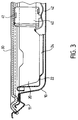
- the thermal reflector 20 shown in Figures 2 and 3 is preferably made of aluminum or any other material reflecting infrared radiation.
- the thermal reflector 20 is also in the form of a tank or container, fixed inside the tank 10 at various contact points, so as to limit the thermal transfer from the thermal reflector 20 to the tank 10.
- the contact points are made for example by 3 or 4 metal pins 21 arranged or welded on the thermal reflector 20 and being housed in the slots 15 provided for this purpose in the tank 10.
- the upper part 2 also comprises a tank 10, a thermal reflector 20 and a cooking plate 31, arranged in an identical or similar manner to the arrangement of said elements in the lower part 1.
- the upper part 2 also includes a cover 2a provided with a handle 2b, facilitating the gripping of the said upper part 2 when the grill appliance is closed or opened.
- the tank 10 in the lower part 1 or upper part 2 has at least 3 slots 15 intended to position and support the thermal reflector 20.
- the slots 15 of the tank 10 can be obtained for example by stamping.
- the lugs 21 are in the form of vertical arms, which can sink into the slots 15, on the one hand and are positioned on the side walls of the thermal reflector 20 so that a bottom 22 of the thermal reflector 20 does not does not come into contact with the tank 10.
- the free space thus obtained between the thermal reflector 20 and the tank 10, except at the contact points defined by the pins 21 and the slots 15 ensures the thermal insulation necessary to optimally reduce thermal losses by conduction.
- the thermal reflector 20 has two openings 23 through which the heating element supported or supported by the orifices 13 of the tank 10. The major part of the thermal reflector 20 is therefore not in contact with the tank 10.
- the latter comprises a groove 24 provided in the bottom 22, said groove 24 being intended to receive a heating element, not shown in the figures.
- the bottom 22 also has a slot 25 through which a support 40 of a thermal sensor emerges.
- the support 40 shown in Figures 2 and 3 is a tongue passing through the bottom 22 of the thermal reflector 20 through the slot 25.
- the support 40 is made from a rectangular metal tongue of thickness sufficiently limited to allow folding of said tongue on herself.
- the support 40 is an aluminum tab, but other materials of the ceramic, silicone or high temperature technical plastic type may be suitable.
- the support 40 has a cavity 41 in which the thermal sensor is arranged, facing the cooking plate 30.
- the thermal sensor is arranged in an internal volume, of a part of the support 40 facing the cooking plate 30.
- the internal volume not shown in the figures, produced mechanically by any known means and in particular by stamping, makes it possible to protect the thermal sensor from shocks or possible wear.
- the thickness of the metal cover thus obtained between the thermal sensor and the cooking plate 30, is chosen so as not to substantially alter the performance of said thermal sensor.
- the thickness of the metal cover preferably does not exceed 1 millimeter.
- the support 40 is mechanically linked to an elastic or flexible means of the elastic blade type 42, which allows the support 40 to move elastically in at least one direction.
- the elastic blade 42 having sufficient stiffness to resiliently position or wedge the support 40, in its upper end zone, against the cooking plate 30.
- the elastic blade 42 is preferably mounted on the thermal reflector 20 by means of a notch 26 on either side of the slot 25 and extends between the tank 10 and the thermal reflector 20 in the vicinity of the slot 25.
- the ends of the elastic strip 42 are fixed in said notches 26 by any known means .
- the support 40 is movable elastically in at least one direction.
- the bottom 22 has an elevation in the vicinity of a slot 25, which makes it possible to provide a larger free space between the bottom of the tank 10 and the bottom 22 of the thermal reflector 20.
- the elastic strip 42 extends in the free space delimited by the elevation in the vicinity of the slot 25.
- the cooking plates 30, 31 are removable.
- the elastic blade 42 positions the support 40 in the extreme high position.
- the support 40 is pushed back down when the cooking plate 30 is put in place.
- the baking plate 30 keeps the support 40 stably by the pressure it exerts on the latter.
- the cavity 41 for example is therefore constantly at the same distance from the cooking plate 30.
- the thermal sensor is disposed in the cavity 41 formed in a part of the support 40 facing the cooking plate 30.
- the thermal sensor can, according to an alternative embodiment, be in direct contact with the cooking plate 30.
- the thermal sensor is in contact with the cooking plate 30 by means of an electrically insulating layer or sheath surrounding said thermal sensor.
- the electrical insulating layer or sheath surrounding the thermal sensor consists of polytetrafluoroethylene for example, having a thickness of a few tenths of a millimeter and preferably 1 tenth of a millimeter.
- the cooking plate 30 has a housing, not shown in the figures, intended to receive and position the support 40. Thus the upper upper part of the support 40, facing the cooking plate 30, is slightly introduced into this housing.
- the thermal sensor consists of a thermo-variable resistor of the NTC resistor type housed and maintained in the thermal atmosphere of the cooking plate 30 by means of the support 40 so as to be subjected mainly to the direct thermal flux coming from the heating plate. cooking 30.
- the small size of the thermal sensor such as that of a NTC resistor, for example, housed in the cavity 41 on the one hand, and facing the cooking plate 30 on the other hand allows the thermal sensor to be protected against at least partially infrared radiation emitted directly by the heating elements or reflected by the thermal reflector 20.
- the thermal sensor is therefore subject principally to the direct thermal flux coming from the cooking plate 30.
- the direct thermal flux must be understood as the radiated flux and duct not coming, in a predominant proportion, from the thermal reflector 20 and / or from the heating elements directly.
- the cooking plates 30 and 31 are covered with a layer of high emissivity of the type polytetrafluoroethylene on the surface facing the heating elements and the thermal reflector 20.
- the cooking plates 30 and 31 are made of aluminum and have a thickness less than or equal to 2.5 millimeters.
- the cooking plates 30, 31 are covered on the surfaces facing the heating elements, with a layer of material of high emissivity with respect to the thermal radiation emitted by said heating elements.
- the cooking plate 30 or 31 is preferably made from aluminum or an aluminum-steel-aluminum assembly, the thickness of which preferably does not exceed 2.5 millimeters and the face of which, opposite the heating elements, is covered with a layer of polytetrafluoroethylene for example, with a thickness of a few micrometers and preferably from 20 to 50 micrometers, to increase the absorption coefficient of the radiation from said baking plate 30 or 31.
- the latter absorb the heat flux from the heating elements and the thermal reflector 20 and quickly returns it to the items to be grilled.
- the cooking plates 30 and 31 are covered with a layer or any chemical deposit improving the absorption and therefore the emissivity of said cooking plates 30 and 31.
- the small thickness of the cooking plate 30 or 31, that is to say its low thermal inertia, contributes in association with regulation and / or temperature control means, to produce a grilling appliance with optimized efficiency. .
- the grilling appliance according to the invention no longer uses, during its operation, thermal energy stored or stored in cooking plates 30 and 31.
- the thickness of the cooking plates 30 and 31 is conditioned only by the necessary mechanical rigidity of said cooking plates 30 and 31.
- the article to be grilled, roasted or cooked is trapped between two cooking plates 30 and 31.
- the cooking plates 30 and 31 are obviously fixed on the tank 10 by means of the connecting pieces 11, which keeps said cooking plate 30 integral with the tank 10 and therefore with the lower part 1 as well as keeping the support 40 and the thermal sensor in the regulation position.
- the connecting piece 11 is substantially elastic or flexible so as to allow the user of the grilling appliance to separate the cooking plate 30 or 31 from the grilling appliance in order to clean it.
- the thermal sensor When replacing the cooking plate 30, which is preferably wavy, the thermal sensor returns to an ideal position under the cooking plate 30 by means of the elastic blade 42 exerting elastic pressure on the support 40
- the degrees of freedom, of the rotational type, of the support 40 obtained by a sufficiently wide slot 25 thus make it possible to use in a grilling appliance according to the invention baking sheets 30 of different structure or external shape.
- the thermal sensor will, whatever happens, always be brought into an ideal position for regulating the temperature of said cooking plate 30.
- a thermal limiter is arranged on the outside of the tank 10 of the upper part 2 of the broiler to maintain the temperature of said tank 10 below the thermal threshold tolerated by the frame, made for example of plastic material. low cost, polypropylene type.
- the thermal limiter therefore constitutes an additional safety means, which cuts off the electrical supply to the heating elements when the temperature of the tank 10 exceeds, for example 250 ° Celcius.
- the distance between the upper part 2 or lower part 1 and the metal parts of the grilling appliance according to the invention is at least equal to 2 millimeters to avoid any risk of direct contact.
- the thermal sensor preferably consisting of a thermovariable electrical resistance of the NTC resistance type is in contact with the cooking plate 30 by means of an electrically insulating and thermally resistant sheath or layer surrounding said thermal sensor.
- the electrical insulating sheath covers only the electrical wires connected to the NTC resistor, which being intrinsically covered with an electrical insulating material.
- the thermal sensor is in thermal contact with at least one hob 30 or 31.
- the grilling appliance according to the invention is advantageously made in two parts which can be folded one over the other for grilling, baking or roasting on two different faces.
- the thermal sensor will then be in contact with the lower cooking plate 30, preferably, because it is on the latter that water and fat from the cooking stagnate or flow, which strongly influences the regulation. in cooking temperature.
- the thermal sensor is a NTC resistor surrounded or wrapped in an electrically insulating and thermally resistant layer or sheath.
- the material with which the CTN resistor is surrounded is preferably polytetrafluoroethylene. The reduced size of a NTC resistor thus makes it possible to produce a thermal sensor with very low thermal inertia.
- Such a thermal sensor gives a faithful and instantaneous image of the temperature of the cooking plate 30.
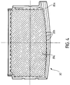
- the presence of liquids on the cooking plate 30 can effectively affect the proper functioning of the grilling appliance, since an amount of thermal energy significant is necessary to evaporate said liquids and especially to pass them from a liquid phase to a vapor phase, which causes significant heat loss. It is therefore desirable to slightly incline the cooking plates 30 and 31 with an inclination of the order of 7 degrees in order to promote rapid flow of the liquids and juices from the article to be grilled, in particular in cavities 30b corrugations 30c, which may have the cooking plate 30.
- at least the cooking plate 30 is inclined by construction of said device with respect to a horizontal direction for discharging the juices from the cooking.
- corrugations 30c a configuration such that the flows converge or are directed towards a flow channel 30a, represented in FIG. 4 and produced on the lower cooking plate 30 and opening towards the outside of the grill appliance.
- the tank 10 has as such a groove 14 substantially matching the shape of the flow channel 30a formed on the cooking plate 30.
- the inclination of the plates cooking is compensated by any known mechanical means.
- the thermal sensor which is surrounded by an electrical insulating layer, is associated with an electronic regulation and / or control circuit for controlling the electrical supply of the heating elements.
- the frame is made from a metal structure.
- the thermal sensor consists of a PTC resistance or a radial NTC resistance.
- An advantage of the grilling appliance according to the invention lies in the production of a support 40 for the thermal sensor, which is flexible and flexible, by means of its attachment to an elastic blade 42, which positions the thermal sensor of optimally to obtain a perfect and instantaneous image of the temperature of the cooking plate 30.
- a support 40 for the thermal sensor which is flexible and flexible, by means of its attachment to an elastic blade 42, which positions the thermal sensor of optimally to obtain a perfect and instantaneous image of the temperature of the cooking plate 30.
- Another advantage of the grilling appliance according to the invention lies in the use of removable cooking plates 30 and 31, which makes it possible to clean them very easily after cooking.
- An additional advantage of the grilling appliance according to the invention is obtained by means of a reliable and precise temperature regulation in order to carry out successive cooking of food articles while in no way altering the quality of cooking or toasting time or cooking time.
- Another advantage of the grilling appliance according to the invention lies in the use of inexpensive materials such as polypropylene or thin metal parts to produce the appliance.
- Another advantage of the grilling appliance according to the invention is obtained by the association of metallic elements and heating elements having a low thermal inertia.
- Another advantage of the grilling appliance according to the invention lies in the control of heat fluxes by simple, inexpensive structural and functional means, said appliance operating with performance optimal without presenting dangers of use towards the user.
- An additional advantage of the grilling appliance according to the invention resides on the one hand in a reduced dispersion of the temperature of the cooking plate 30, and on the other hand in obtaining a preheating time reduced to 2 minutes 15 seconds. Furthermore, the grilling appliance according to the invention has the advantage of reducing the reaction time, after the pause for food to be grilled on the baking sheet 30, to a time of between 3 and 15 seconds, making it possible to this way of obtaining a saving of time on long cooking such as ribs of beef or minced steaks for example, and especially an improvement of the grilling of steaks in the case of successive cooking.
Landscapes
- Engineering & Computer Science (AREA)
- Food Science & Technology (AREA)
- Baking, Grill, Roasting (AREA)
- Packging For Living Organisms, Food Or Medicinal Products That Are Sensitive To Environmental Conditiond (AREA)
- Meat, Egg Or Seafood Products (AREA)
Applications Claiming Priority (2)
| Application Number | Priority Date | Filing Date | Title |
|---|---|---|---|
| FR9315131 | 1993-12-10 | ||
| FR9315131A FR2713464B1 (fr) | 1993-12-10 | 1993-12-10 | Structure et agencement de pièces constitutives d'un gril-viande à coque plastique. |
Publications (2)
| Publication Number | Publication Date |
|---|---|
| EP0657132A1 true EP0657132A1 (de) | 1995-06-14 |
| EP0657132B1 EP0657132B1 (de) | 1999-07-14 |
Family
ID=9453999
Family Applications (1)
| Application Number | Title | Priority Date | Filing Date |
|---|---|---|---|
| EP94420350A Expired - Lifetime EP0657132B1 (de) | 1993-12-10 | 1994-12-09 | Form und Anordnung der Bauelemente eines Fleischgrillgerätes mit Kunststoffgehäuse |
Country Status (5)
| Country | Link |
|---|---|
| EP (1) | EP0657132B1 (de) |
| AT (1) | ATE182061T1 (de) |
| DE (1) | DE69419484T2 (de) |
| FR (1) | FR2713464B1 (de) |
| GR (1) | GR3031230T3 (de) |
Cited By (3)
| Publication number | Priority date | Publication date | Assignee | Title |
|---|---|---|---|---|
| EP1188401A1 (de) * | 2000-09-18 | 2002-03-20 | Seb S.A. | Elektrischer Gartengrill mit einem Heizungsbegrenzer |
| EP1400193A1 (de) * | 2002-09-20 | 2004-03-24 | Seb Sa | Haube von einem elektrischen Waffeleisen |
| EP2293646A3 (de) * | 2009-09-02 | 2011-11-23 | Caspar Cloer GmbH & Co. KG | Gerät zur Zubereitung warmer Speisen |
Families Citing this family (2)
| Publication number | Priority date | Publication date | Assignee | Title |
|---|---|---|---|---|
| DE10241139A1 (de) * | 2002-09-05 | 2004-03-18 | BSH Bosch und Siemens Hausgeräte GmbH | Heizeinrichtung eines elektrischen Toasters oder Grillgerätes |
| CN200998178Y (zh) | 2007-01-17 | 2008-01-02 | 厦门灿坤实业股份有限公司 | 掀盖式煎烤器 |
Citations (7)
| Publication number | Priority date | Publication date | Assignee | Title |
|---|---|---|---|---|
| US2040369A (en) * | 1935-06-12 | 1936-05-12 | Knapp Monarch Co | Electrical appliance |
| FR2302067A1 (fr) * | 1975-02-25 | 1976-09-24 | Seb Sa | Gril electrique perfectionne |
| FR2400302A1 (fr) * | 1977-08-08 | 1979-03-09 | Sedor | Multicuiseur |
| GB2140672A (en) * | 1983-05-12 | 1984-12-05 | Dean Bridge | Griddle unit |
| US4862795A (en) * | 1988-06-06 | 1989-09-05 | General Electric Company | Cooktop grill with improved reflector pan |
| JPH02301968A (ja) * | 1989-04-25 | 1990-12-14 | Linde Ag | 燃料電池の稼働方法 |
| AU627142B3 (en) * | 1992-03-18 | 1992-06-26 | Tsann-Kuen Wu | Improved oven |
-
1993
- 1993-12-10 FR FR9315131A patent/FR2713464B1/fr not_active Expired - Fee Related
-
1994
- 1994-12-09 AT AT94420350T patent/ATE182061T1/de not_active IP Right Cessation
- 1994-12-09 DE DE69419484T patent/DE69419484T2/de not_active Expired - Fee Related
- 1994-12-09 EP EP94420350A patent/EP0657132B1/de not_active Expired - Lifetime
-
1999
- 1999-09-16 GR GR990402321T patent/GR3031230T3/el unknown
Patent Citations (7)
| Publication number | Priority date | Publication date | Assignee | Title |
|---|---|---|---|---|
| US2040369A (en) * | 1935-06-12 | 1936-05-12 | Knapp Monarch Co | Electrical appliance |
| FR2302067A1 (fr) * | 1975-02-25 | 1976-09-24 | Seb Sa | Gril electrique perfectionne |
| FR2400302A1 (fr) * | 1977-08-08 | 1979-03-09 | Sedor | Multicuiseur |
| GB2140672A (en) * | 1983-05-12 | 1984-12-05 | Dean Bridge | Griddle unit |
| US4862795A (en) * | 1988-06-06 | 1989-09-05 | General Electric Company | Cooktop grill with improved reflector pan |
| JPH02301968A (ja) * | 1989-04-25 | 1990-12-14 | Linde Ag | 燃料電池の稼働方法 |
| AU627142B3 (en) * | 1992-03-18 | 1992-06-26 | Tsann-Kuen Wu | Improved oven |
Non-Patent Citations (1)
| Title |
|---|
| PATENT ABSTRACTS OF JAPAN vol. 15, no. 86 (E - 1039) 28 February 1991 (1991-02-28) * |
Cited By (6)
| Publication number | Priority date | Publication date | Assignee | Title |
|---|---|---|---|---|
| EP1188401A1 (de) * | 2000-09-18 | 2002-03-20 | Seb S.A. | Elektrischer Gartengrill mit einem Heizungsbegrenzer |
| FR2814056A1 (fr) * | 2000-09-18 | 2002-03-22 | Seb Sa | Appareil electrique de cuisson du type barbecue, a limitation de chauffe |
| EP1400193A1 (de) * | 2002-09-20 | 2004-03-24 | Seb Sa | Haube von einem elektrischen Waffeleisen |
| FR2844694A1 (fr) * | 2002-09-20 | 2004-03-26 | Seb Sa | Capot d'appareil electrique du type gaufrier |
| EP1557120A1 (de) * | 2002-09-20 | 2005-07-27 | Seb Sa | Haube von einem elektronischen Waffeleisen |
| EP2293646A3 (de) * | 2009-09-02 | 2011-11-23 | Caspar Cloer GmbH & Co. KG | Gerät zur Zubereitung warmer Speisen |
Also Published As
| Publication number | Publication date |
|---|---|
| DE69419484D1 (de) | 1999-08-19 |
| DE69419484T2 (de) | 2000-01-20 |
| FR2713464B1 (fr) | 1996-01-19 |
| FR2713464A1 (fr) | 1995-06-16 |
| EP0657132B1 (de) | 1999-07-14 |
| ATE182061T1 (de) | 1999-07-15 |
| GR3031230T3 (en) | 1999-12-31 |
Similar Documents
| Publication | Publication Date | Title |
|---|---|---|
| EP2185046B1 (de) | Heisswasserbereiter für eine getränkezubereitungsmaschine | |
| WO2009156190A1 (fr) | Chaudiere pour machine de preparation de boissons chaudes | |
| FR3012008A1 (fr) | Element chauffant a couche epaisse et equipement de cuisine comportant un tel element chauffant | |
| EP2434933B1 (de) | Elektrhaushaltsgerät für speisenzubereitung mit eienr basis zur aufnahme eines arbeitsgefässes mit einer wärmeplatte | |
| FR2750590A1 (fr) | Friteuse a cuve amovible | |
| EP1033929B1 (de) | Elektrisches kochgerät, insbesondere ein fritiergerät, mit einem flachen heizelement mit durch siebdruck hergestelltem widerstand | |
| EP0657132B1 (de) | Form und Anordnung der Bauelemente eines Fleischgrillgerätes mit Kunststoffgehäuse | |
| FR2614976A1 (fr) | Four electrique pour la cuisson des aliments comprenant un generateur de vapeur | |
| EP0657133B1 (de) | NTC-Temperaturfühler auf nachgiebigem Träger in einem Fleischgrillgerät | |
| FR2956573A1 (fr) | Appareil de cuisson electrique | |
| EP1400193B1 (de) | Haube von einem elektrischen Waffeleisen | |
| WO2001078567A1 (fr) | Toit perfectionne pour grille-pain | |
| EP1824366B1 (de) | Tragbare nahrungsmittelerhitzungsvorrichtung | |
| EP1400194B1 (de) | Heizbaugruppe eines elektrischen Apparates vom Typ eines Waffeleisens | |
| EP2965672A1 (de) | Kochgerät | |
| EP0914023A2 (de) | Elektrisches Gargerät, insbesondere Friteuse | |
| EP1294261A2 (de) | Heizgefäss als haushaltsgerät zur erwärmung von flüssigkeit | |
| EP2401948B1 (de) | Elektrisches Kochgerät mit Kessel und Reflektor | |
| EP0739153B1 (de) | Auf einem Träger hartaufgelötetes Heizelement | |
| WO2000040130A1 (fr) | Friteuse electrique | |
| EP0686368A1 (de) | Bewegliches Heizelement für elektrisches Gargerät | |
| WO2006053964A1 (fr) | Barbecue electrique a reflecteur flottant | |
| EP1333261A1 (de) | Temperatursensor für ein elektrisches Haushaltsgerät mit abnehmbarem Element | |
| FR2882638A3 (fr) | Dispositif de cuisson ayant une structure non-conductrice | |
| BE566056A (de) |
Legal Events
| Date | Code | Title | Description |
|---|---|---|---|
| PUAI | Public reference made under article 153(3) epc to a published international application that has entered the european phase |
Free format text: ORIGINAL CODE: 0009012 |
|
| AK | Designated contracting states |
Kind code of ref document: A1 Designated state(s): AT BE CH DE ES GB GR IT LI NL PT |
|
| 17P | Request for examination filed |
Effective date: 19950614 |
|
| RAP1 | Party data changed (applicant data changed or rights of an application transferred) |
Owner name: SEB S.A. |
|
| 17Q | First examination report despatched |
Effective date: 19970212 |
|
| GRAG | Despatch of communication of intention to grant |
Free format text: ORIGINAL CODE: EPIDOS AGRA |
|
| GRAG | Despatch of communication of intention to grant |
Free format text: ORIGINAL CODE: EPIDOS AGRA |
|
| GRAH | Despatch of communication of intention to grant a patent |
Free format text: ORIGINAL CODE: EPIDOS IGRA |
|
| GRAH | Despatch of communication of intention to grant a patent |
Free format text: ORIGINAL CODE: EPIDOS IGRA |
|
| GRAA | (expected) grant |
Free format text: ORIGINAL CODE: 0009210 |
|
| AK | Designated contracting states |
Kind code of ref document: B1 Designated state(s): AT BE CH DE ES GB GR IT LI NL PT |
|
| PG25 | Lapsed in a contracting state [announced via postgrant information from national office to epo] |
Ref country code: GB Free format text: LAPSE BECAUSE OF FAILURE TO SUBMIT A TRANSLATION OF THE DESCRIPTION OR TO PAY THE FEE WITHIN THE PRESCRIBED TIME-LIMIT Effective date: 19990714 Ref country code: ES Free format text: THE PATENT HAS BEEN ANNULLED BY A DECISION OF A NATIONAL AUTHORITY Effective date: 19990714 Ref country code: AT Free format text: LAPSE BECAUSE OF FAILURE TO SUBMIT A TRANSLATION OF THE DESCRIPTION OR TO PAY THE FEE WITHIN THE PRESCRIBED TIME-LIMIT Effective date: 19990714 |
|
| REF | Corresponds to: |
Ref document number: 182061 Country of ref document: AT Date of ref document: 19990715 Kind code of ref document: T |
|
| REG | Reference to a national code |
Ref country code: CH Ref legal event code: EP |
|
| REF | Corresponds to: |
Ref document number: 69419484 Country of ref document: DE Date of ref document: 19990819 |
|
| ITF | It: translation for a ep patent filed |
Owner name: MAROSCIA & ASSOCIATI S.R.L. |
|
| PG25 | Lapsed in a contracting state [announced via postgrant information from national office to epo] |
Ref country code: PT Free format text: LAPSE BECAUSE OF FAILURE TO SUBMIT A TRANSLATION OF THE DESCRIPTION OR TO PAY THE FEE WITHIN THE PRESCRIBED TIME-LIMIT Effective date: 19991014 |
|
| PG25 | Lapsed in a contracting state [announced via postgrant information from national office to epo] |
Ref country code: LI Free format text: LAPSE BECAUSE OF NON-PAYMENT OF DUE FEES Effective date: 19991231 Ref country code: CH Free format text: LAPSE BECAUSE OF NON-PAYMENT OF DUE FEES Effective date: 19991231 |
|
| GBV | Gb: ep patent (uk) treated as always having been void in accordance with gb section 77(7)/1977 [no translation filed] |
Effective date: 19990714 |
|
| PLBE | No opposition filed within time limit |
Free format text: ORIGINAL CODE: 0009261 |
|
| STAA | Information on the status of an ep patent application or granted ep patent |
Free format text: STATUS: NO OPPOSITION FILED WITHIN TIME LIMIT |
|
| 26N | No opposition filed | ||
| PGFP | Annual fee paid to national office [announced via postgrant information from national office to epo] |
Ref country code: NL Payment date: 20031031 Year of fee payment: 10 |
|
| PGFP | Annual fee paid to national office [announced via postgrant information from national office to epo] |
Ref country code: GR Payment date: 20031107 Year of fee payment: 10 |
|
| PGFP | Annual fee paid to national office [announced via postgrant information from national office to epo] |
Ref country code: BE Payment date: 20041112 Year of fee payment: 11 |
|
| PGFP | Annual fee paid to national office [announced via postgrant information from national office to epo] |
Ref country code: DE Payment date: 20041208 Year of fee payment: 11 |
|
| PG25 | Lapsed in a contracting state [announced via postgrant information from national office to epo] |
Ref country code: NL Free format text: LAPSE BECAUSE OF NON-PAYMENT OF DUE FEES Effective date: 20050701 |
|
| PG25 | Lapsed in a contracting state [announced via postgrant information from national office to epo] |
Ref country code: GR Free format text: LAPSE BECAUSE OF NON-PAYMENT OF DUE FEES Effective date: 20050704 |
|
| NLV4 | Nl: lapsed or anulled due to non-payment of the annual fee |
Effective date: 20050701 |
|
| PG25 | Lapsed in a contracting state [announced via postgrant information from national office to epo] |
Ref country code: IT Free format text: LAPSE BECAUSE OF NON-PAYMENT OF DUE FEES;WARNING: LAPSES OF ITALIAN PATENTS WITH EFFECTIVE DATE BEFORE 2007 MAY HAVE OCCURRED AT ANY TIME BEFORE 2007. THE CORRECT EFFECTIVE DATE MAY BE DIFFERENT FROM THE ONE RECORDED. Effective date: 20051209 |
|
| PG25 | Lapsed in a contracting state [announced via postgrant information from national office to epo] |
Ref country code: BE Free format text: LAPSE BECAUSE OF NON-PAYMENT OF DUE FEES Effective date: 20051231 |
|
| PG25 | Lapsed in a contracting state [announced via postgrant information from national office to epo] |
Ref country code: DE Free format text: LAPSE BECAUSE OF NON-PAYMENT OF DUE FEES Effective date: 20060701 |
|
| BERE | Be: lapsed |
Owner name: S.A. *SEB Effective date: 20051231 |