EP0657115B1 - A fastening device for sporting foot-wear, in particular for ski-boot - Google Patents
A fastening device for sporting foot-wear, in particular for ski-boot Download PDFInfo
- Publication number
- EP0657115B1 EP0657115B1 EP94203486A EP94203486A EP0657115B1 EP 0657115 B1 EP0657115 B1 EP 0657115B1 EP 94203486 A EP94203486 A EP 94203486A EP 94203486 A EP94203486 A EP 94203486A EP 0657115 B1 EP0657115 B1 EP 0657115B1
- Authority
- EP
- European Patent Office
- Prior art keywords
- fastening device
- hinged
- boot leg
- boot
- shell
- Prior art date
- Legal status (The legal status is an assumption and is not a legal conclusion. Google has not performed a legal analysis and makes no representation as to the accuracy of the status listed.)
- Expired - Lifetime
Links
Images


Classifications
-
- A—HUMAN NECESSITIES
- A43—FOOTWEAR
- A43B—CHARACTERISTIC FEATURES OF FOOTWEAR; PARTS OF FOOTWEAR
- A43B5/00—Footwear for sporting purposes
- A43B5/04—Ski or like boots
- A43B5/0427—Ski or like boots characterised by type or construction details
- A43B5/047—Ski or like boots characterised by type or construction details provided with means to improve walking with the skiboot
- A43B5/0474—Ski or like boots characterised by type or construction details provided with means to improve walking with the skiboot having a walk/ski position
Definitions
- the present invention relates to a fastening device for sporting footwear which comprise reclining portions as for example it occurs in the moto-cross shoes or ski-boots for the "snow-board” or in the mountaineering skiing and, in particular, for the rear tightening of the boot leg for the ski-boots.
- the ski-boots comprise a rigid shell to which a boot leg is hinged having the function to wrap the lower portion of the skier's leg and to allow to vary the bending of the leg with respect to the foot and then to the ski.
- an inner shoe is housed inside the shell and boot leg, a shoe made of soft material.
- the fastening device includes at least a first and a second member hinged between each other at one of their ends, the opposite ends of said members being hinged to the shell and boot leg respectively, one of said member being provided with an operating arm.
- ski-boot With reference to the way by which the foot is put into the ski-boot, there exist substantially two kinds of ski-boots.
- a first type the so-called front-entry ski-boot, wherein usually there are two flaps on the front portion of the ski-boot defining an opening that can be opened wide through which the foot is put into.
- the second type known as rear-entry ski-boot, consists of a shell, a front tongue and a boot leg.
- ski-boots allow a more easy entry of the foot into the ski-boot. Furthermore these ski-boots have a good seal against water and snow.
- ski-boots have some drawbacks due to the fact that, in order to allow the entry of the foot, the distance between the ski-boot portion corresponding to the instep and the ski-boot portion wherein the heel is housed, must be increased.
- central-entry ski-boots have been conceived and made which are similar to the rear-entry ski-boots, these ski-boots, however, being provided with devices which allow the backward inclination of the boot leg with respect to the shell in order to facilitate the entry of the foot thus achieving the usual advantages of the rear-entry ski-boots.
- Such a kind of ski-boots has another advantage which consists in facilitating walking when the boot leg is inclinated backwards.
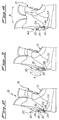
- Figure 9 illustrates the device in fastened position wherein the boot leg is inclined forwards. Starting from this position and acting onto the crank hinged to the shell so as to move the crank away from the boot leg, the device is released and the pins 30 and 35 are more near and, consequently the boot leg inclines backwards. In order to take again the boot leg to the initial position and to fasten the device, it is sufficient to pull up the same crank up to the previous position.
- the above described device have various drawbacks owing to the fact that during the walking activity, when the the boot leg is backward inclined, as indicated in figures 10 and 11, the device projects from the boot leg.
- a device projecting from the rear part of the ski-boot may hinder the already difficult walk.
- the device might knock on obstacles thus undergoing damages or even hit the surrounding people thus causing possible accidents.
- EP-A-0248149 discloses a ski-boot comprising a fastening device interposed between the shell and the boot leg of the ski-boot, said fastening device being actionable to bring the ski-boot from the skiing condition to the walking condition and viceversa, the operation of the fastening device involving previously the rotation of the boot leg.
- the aim of the present invention consists in making a fastening device for sporting footwear which in the case of the ski-boots allow a backward overturning of the boot leg thus obtaining the twofold function of facilitating the entry of the foot into the ski-boot achieving the above-mentioned advantages and, moreover, to allow the leg to take an optimum position with respect to the shell in order to facilitate walking.
- Another important aim consists in making the device in such a way that it does not project outwards with respect to the boot leg, both in the forward inclined position utilized for skiing and in the backward inclined position utilized for putting on the ski-boot or for walking.
- a fastening device interposed between said shell and boot leg and characterized in that the first member consists of, at least, two structural portions connected between each other at one of their ends so as to be movable between each other making the first member extensible.
- the second member is a crank whereas the first member consists of a telescopically extendible crank.
- the boot leg has a seat suitable for housing the device both in the fastened operative position wherein the boot leg is forwards inclined and in the released position wherein the boot leg is backwards overturned thus eliminating the drawbacks explained with reference to the mentioned prior art.
- the device allows the skier to take again the boot leg to the position for skiing, facilitating the hooking of the levers to the racks whereas this operation is difficult in the present shoes.
- a ski-boot is indicated with reference 10 as a whole, comprising a rigid shell 12 hinged to a boot leg 18 by pins 20 allowing a relative rotation between the boot leg and the shell on a tranverse axis.
- a fastening device 22 is interposed between said shell 12 and boot leg 18 on their rear part to allow the backward movement of the boot leg as will be more explained later.
- the fastening device 22 comprises a first and a second crank indicated with reference 24 and 26 and, respectively, hinged to the shell 12 and boot leg 18 by respective pins 28 and 30 and hinged between each other by a pin 32.
- the axes of the pins 28, 30 and 32 are perpendicular to the center longitudinal plane of the ski-boot 10 whereby the device movement occur substantially in this plane.
- the first crank 24 comprises two structural portions 34 and 36: the first one is hinged to the boot leg 18 by the pin 28 whereas the second one is hinged to the second crank 26 by the pin 32.
- the second portion 36 is tubular shaped and inside it the first portion 34 slides so as to from a telescopic structure, as illustrated in figure 5.
- a helicoidal spring 38 is housed inside the second portion 36 and interposed between the latter and the first portion 34, a spring having the function of reduce the oscillations which may occur during the operating of the fastening device 22.
- the operating of the crank 26 is facilitated by an arm 40 extending on the opposite side of the crank with respect to the pin 30.
- the pin 28 is adjustable along a slit 42 made in the shell 12 allowing the inclination of the boot leg 18 to vary with respect to the shell, both when the device is fastened and the boot leg is forwards positioned and when the device is released and the boot leg is backwards positioned.
- the fastening device 22 is entirely housed inside a seat 44 made in the boot leg 18.
- figure 2 depicts the situation wherein the pin 32 which joins the two cranks 24 and 26 is interposed between the two pins 28 and 30. In such a position, the first portion 34 of the crank 24 is entirely inside the second portion 36 whereas the operating arm 40 and thus the second crank 26 are fastened.
- the boot leg 18 may be overturned backwards, as indicated by arrow B in figure 4, up to reach the position depicted in the same figure wherein the first portion 34 is entirely inserted in the second portion 36 preventing the boot leg to further rotate backwards.
- Such a limit position depends on the maximum variation in the lengh of the first crank 24.
- a modified embodiment of the fastening device according to the present invention consists of a device similar to the previous one wherein the first crank, hinged to the shell, is of a predetermined length and provided with an operating arm on the opposite side of the same crank with respect to the point in which it is hinged to the shell and the second crank, hinged to the boot leg, is telescopically extendible.
- the same numeral references of the preceding embodiment will be used to indicate similar or analogous members.
- the pin 32 By rotating the operating arm 40, at about 180°, the pin 32 reaches the position located on the opposite side of the pin 30 with respect to the pin 28 and the second crank 26 lenghtens. Therefore, the boot leg 18 may be overturned backwards, consequently reducing the length of the second crank, up to reach the position wherein the crank is entirely retracted.
- the fastening device is housed inside the seat suitably made in the boot leg, not only when the device is fastened and the boot leg in such a position to allow the skiing activity, but also when the same is released and the boot leg is in the position upright to facilitate the deambulation.
- the device which does not projects from the boot leg during the walking activity when it is in the upright position, allows a reduction of the possibility that the skier may stumble while he walks.
- the possible damages, which the device might undergo owing to collisions are eliminated.
- a further improvement of this invention may consist of the possibility of gradually moving the support point of the first crank to the shell to permit a greater forward inclination of the boot leg.
- the device may be provided with a spring structure, in combination with the latter feature of the device or alone, which, when loaded, may limit the forward flexibility of the ski-boot.
- the numeral 40 indicates again the operating arm, to which a drawer member 136, corresponding to the tubolar structural member 36 of figure 5, is attached.
- the drawer member 136 houses inside a pin 34 (equivalent to the structural member 34 of figure 5), on the outer surface of which a threaded nut 142 is mounted, the position of which along the pin 134 may be adjusted from the outside acting onto the outer surface.
- a compression spring 138 is interposed between the bottom of the drawer member 136 and the nut 142, a spring having the same cushioning function of the spring 38 of figure 5.
- the lower end of the pin 134 is integral with a knob 144 by means of threads whereby the knob may be moved along the axis of the pin 134.
- the device may be used for the side fastening of the "snow-board" ski-boots or for the fastening of the front tongue of the mountaineering ski-boots.
Landscapes
- Health & Medical Sciences (AREA)
- General Health & Medical Sciences (AREA)
- Physical Education & Sports Medicine (AREA)
- Footwear And Its Accessory, Manufacturing Method And Apparatuses (AREA)
Abstract
Description
- The present invention relates to a fastening device for sporting footwear which comprise reclining portions as for example it occurs in the moto-cross shoes or ski-boots for the "snow-board" or in the mountaineering skiing and, in particular, for the rear tightening of the boot leg for the ski-boots.
- With reference to the latter case, it is known that the ski-boots comprise a rigid shell to which a boot leg is hinged having the function to wrap the lower portion of the skier's leg and to allow to vary the bending of the leg with respect to the foot and then to the ski. Finally, in order to make more comfortable the fit of the ski-boot, an inner shoe is housed inside the shell and boot leg, a shoe made of soft material.
- The fastening device includes at least a first and a second member hinged between each other at one of their ends, the opposite ends of said members being hinged to the shell and boot leg respectively, one of said member being provided with an operating arm.
- With reference to the way by which the foot is put into the ski-boot, there exist substantially two kinds of ski-boots. A first type, the so-called front-entry ski-boot, wherein usually there are two flaps on the front portion of the ski-boot defining an opening that can be opened wide through which the foot is put into. The second type, known as rear-entry ski-boot, consists of a shell, a front tongue and a boot leg.
- It clearly appears that the rear-entry ski-boots allow a more easy entry of the foot into the ski-boot. Furthermore these ski-boots have a good seal against water and snow.
- However, these ski-boots have some drawbacks due to the fact that, in order to allow the entry of the foot, the distance between the ski-boot portion corresponding to the instep and the ski-boot portion wherein the heel is housed, must be increased.
- Consequently, the tickness of the shoe portion corresponding to the instep must be increased achieving a little effective contact between the foot and the ski-boot.
- At least, another problem is the lack of the boot leg inclination adjusting with respect to the shell.
- Therefore, central-entry ski-boots have been conceived and made which are similar to the rear-entry ski-boots, these ski-boots, however, being provided with devices which allow the backward inclination of the boot leg with respect to the shell in order to facilitate the entry of the foot thus achieving the usual advantages of the rear-entry ski-boots.
- Such a kind of ski-boots has another advantage which consists in facilitating walking when the boot leg is inclinated backwards.
- An embodiment is depicted in European Patent Application No.0229405, the figures 9 to 12 of which depict a fastening device comprising two cranks 29,31 hinged between each other by a
pin 32 and, respectively, hinged to the shell 1 and to the boot leg 2 by means ofrespective pins 30 and 35. - Figure 9 illustrates the device in fastened position wherein the boot leg is inclined forwards. Starting from this position and acting onto the crank hinged to the shell so as to move the crank away from the boot leg, the device is released and the
pins 30 and 35 are more near and, consequently the boot leg inclines backwards. In order to take again the boot leg to the initial position and to fasten the device, it is sufficient to pull up the same crank up to the previous position. - However, the above described device have various drawbacks owing to the fact that during the walking activity, when the the boot leg is backward inclined, as indicated in figures 10 and 11, the device projects from the boot leg. In fact, when considering that during the sporting activity the skier walks in an awkward way owing to the heavy clothes and sporting equipments such as the skis, a device projecting from the rear part of the ski-boot may hinder the already difficult walk. Furthermore, the device might knock on obstacles thus undergoing damages or even hit the surrounding people thus causing possible accidents. EP-A-0248149 discloses a ski-boot comprising a fastening device interposed between the shell and the boot leg of the ski-boot, said fastening device being actionable to bring the ski-boot from the skiing condition to the walking condition and viceversa, the operation of the fastening device involving previously the rotation of the boot leg.
- The aim of the present invention consists in making a fastening device for sporting footwear which in the case of the ski-boots allow a backward overturning of the boot leg thus obtaining the twofold function of facilitating the entry of the foot into the ski-boot achieving the above-mentioned advantages and, moreover, to allow the leg to take an optimum position with respect to the shell in order to facilitate walking.
- Another important aim consists in making the device in such a way that it does not project outwards with respect to the boot leg, both in the forward inclined position utilized for skiing and in the backward inclined position utilized for putting on the ski-boot or for walking.
- These aims are achieved by a fastening device interposed between said shell and boot leg and characterized in that the first member consists of, at least, two structural portions connected between each other at one of their ends so as to be movable between each other making the first member extensible.
- In a preferred structural embodiment of the device according to the present invention, the second member is a crank whereas the first member consists of a telescopically extendible crank. Furthermore, in a particular embodiment, the boot leg has a seat suitable for housing the device both in the fastened operative position wherein the boot leg is forwards inclined and in the released position wherein the boot leg is backwards overturned thus eliminating the drawbacks explained with reference to the mentioned prior art.
- Furthermore, the device allows the skier to take again the boot leg to the position for skiing, facilitating the hooking of the levers to the racks whereas this operation is difficult in the present shoes.
- The invention will be depicted with reference to the enclosed drawings which illustrate an embodiment given as a non-limiting example. In the drawings:
- figure 1 is a schematic side view, partially sectioned, of a ski-boot according to the invention wherein the fastening device is depicted in the fastened position;
- figures 2, 3 and 4 are side views of the same ski-boot, partially sectioned, wherein the device is depicted in a fastened situation for sporting activity (fig.2), in a released or walking position (fig.3) whereas figure 4 shows the successive positions of the fastening lever;
- figure 5 is a perspective exploded view of the fastening device;
- figure 6 is schematic view of a modified embodiment of the fastening device.
- In the figures, a ski-boot is indicated with
reference 10 as a whole, comprising arigid shell 12 hinged to aboot leg 18 bypins 20 allowing a relative rotation between the boot leg and the shell on a tranverse axis. - A
fastening device 22 is interposed between saidshell 12 andboot leg 18 on their rear part to allow the backward movement of the boot leg as will be more explained later. - The
fastening device 22 comprises a first and a second crank indicated withreference shell 12 and bootleg 18 byrespective pins pin 32. The axes of thepins boot 10 whereby the device movement occur substantially in this plane. - In particular, the
first crank 24 comprises twostructural portions 34 and 36: the first one is hinged to theboot leg 18 by thepin 28 whereas the second one is hinged to thesecond crank 26 by thepin 32. Thesecond portion 36 is tubular shaped and inside it thefirst portion 34 slides so as to from a telescopic structure, as illustrated in figure 5. Ahelicoidal spring 38 is housed inside thesecond portion 36 and interposed between the latter and thefirst portion 34, a spring having the function of reduce the oscillations which may occur during the operating of thefastening device 22. The operating of thecrank 26 is facilitated by anarm 40 extending on the opposite side of the crank with respect to thepin 30. - The
pin 28 is adjustable along a slit 42 made in theshell 12 allowing the inclination of theboot leg 18 to vary with respect to the shell, both when the device is fastened and the boot leg is forwards positioned and when the device is released and the boot leg is backwards positioned. - Both in the fastening position represented in figures 1 and 2 and in the released position represented in figure 4 illustrating the forward and backward positions of the boot leg respectively, the
fastening device 22 is entirely housed inside aseat 44 made in theboot leg 18. - In order to better understand the operating of the fastening device, it is important to point out that, starting from the boot leg position illustrated in figure 2, position which occurs during the skiing activity, a rotation backward of the
boot leg 18 on the axis of thepin 20 causes thepins pin 32 which joins the twocranks pins first portion 34 of thecrank 24 is entirely inside thesecond portion 36 whereas theoperating arm 40 and thus thesecond crank 26 are fastened. - Since the
second crank 26 is fastened and thefirst crank 24 is unable to shorten, the twopins boot leg 18 is prevented. - By rotating the
second crank 26, at about 180° degrees, by theoperating arm 40, as indicated by arrow A in figure 3, and fastening it in such a position, thepin 32 joining the twocranks pin 28 with respect to thepin 30, as depicted in figure 4. In such a position, theoperating arm 40 and then thesecond crank 26 are fastened whereas thefirst crank 24 is at most lenghtened. - Consequently, the
boot leg 18 may be overturned backwards, as indicated by arrow B in figure 4, up to reach the position depicted in the same figure wherein thefirst portion 34 is entirely inserted in thesecond portion 36 preventing the boot leg to further rotate backwards. Such a limit position depends on the maximum variation in the lengh of thefirst crank 24. - In order to take the
boot leg 18 to the previous position and to fasten the device, it is sufficient to rotate theoperating arm 40; consequently, thesecond crank 26 rotates on itspin 30 and thepin 32 joining the two cranks moves to an intermediate position between the twopins pins first crank 24. Since thefirst crank 24 is entirely retracted and it cannot be shortened further, the twopins boot leg 18 is compelled to move forwards and, when theoperating arm 40 reaches the initial position, the boot leg is inclined forwards (see figura 2). Finally, by fastening theoperating arm 40, theboot leg 18 is prevented from rotating backwards. - An alternative, to take the
boot leg 18 to the initial position and to fasten the device, consists in inclining forwards theboot leg 18, whereas, at the same time, thefirst crank 24 lenghtens thus reaching the position wherein it is entirely lenghtened and the boot leg forwards inclined. Later, it is sufficient to rotate, at 180° degrees approximately, thesecond crank 26 by theoperating arm 40 thus reaching the position depicted in figure 2 wherein thefirst crank 24 is entirely retracted preventing theboot leg 18 from inclining backwards. - It is self-evident that modifications and changes conceptually and functionally equivalent are possible and expected remaining, however, within the scope of the present invention.
- For example, a modified embodiment of the fastening device according to the present invention consists of a device similar to the previous one wherein the first crank, hinged to the shell, is of a predetermined length and provided with an operating arm on the opposite side of the same crank with respect to the point in which it is hinged to the shell and the second crank, hinged to the boot leg, is telescopically extendible. For clearness purposes the same numeral references of the preceding embodiment will be used to indicate similar or analogous members.
- In the situation wherein the device is fastened, the
operating arm 40 and then thefirst crank 24 are fastened, thepin 32 joining the two cranks is interposed between thepins second crank 26 is completely retracted. Consequently, any backward inclination of theboot leg 18 is prevented since the distance between the twopins - By rotating the
operating arm 40, at about 180°, thepin 32 reaches the position located on the opposite side of thepin 30 with respect to thepin 28 and thesecond crank 26 lenghtens. Therefore, theboot leg 18 may be overturned backwards, consequently reducing the length of the second crank, up to reach the position wherein the crank is entirely retracted. - In order to take the
boot leg 18 to its original position and to fasten thedevice 22, it is sufficient, as previously described, to rotate theoperating arm 40, at about 180° or alternatively, to move the boot leg forwards and successively rotate theoperating arm 40 fastening thedevice 22. - This invention has several advantages due to the fact that the fastening device is housed inside the seat suitably made in the boot leg, not only when the device is fastened and the boot leg in such a position to allow the skiing activity, but also when the same is released and the boot leg is in the position upright to facilitate the deambulation. For example, it is possible to easily note that the device, which does not projects from the boot leg during the walking activity when it is in the upright position, allows a reduction of the possibility that the skier may stumble while he walks. Moreover, the possible damages, which the device might undergo owing to collisions, are eliminated.
- A further improvement of this invention may consist of the possibility of gradually moving the support point of the first crank to the shell to permit a greater forward inclination of the boot leg.
- The device may be provided with a spring structure, in combination with the latter feature of the device or alone, which, when loaded, may limit the forward flexibility of the ski-boot.
- This modified embodiment is illustrated in figure 6, wherein the references of the previous figures have been used as much as possible.
- In this case, the numeral 40 indicates again the operating arm, to which a
drawer member 136, corresponding to the tubolarstructural member 36 of figure 5, is attached. Thedrawer member 136 houses inside a pin 34 (equivalent to thestructural member 34 of figure 5), on the outer surface of which a threadednut 142 is mounted, the position of which along thepin 134 may be adjusted from the outside acting onto the outer surface. Acompression spring 138 is interposed between the bottom of thedrawer member 136 and thenut 142, a spring having the same cushioning function of thespring 38 of figure 5. - The lower end of the
pin 134 is integral with aknob 144 by means of threads whereby the knob may be moved along the axis of thepin 134. - From the above description it is self-evident that the embodiment of figure 6 assures, not only, the fastening and releasing functions of the embodiments illustrated in the preceding figures, but it also achieves the following functions:
- a) the adjusting of the maximum inclination of the boot leg by varying
the position of the
knob 144 and - b) the adjusting of the boot leg bending by varying the position of the
nut 142. -
- This invention, as previously stated, may be used in other sporting footwear. For example, the device may be used for the side fastening of the "snow-board" ski-boots or for the fastening of the front tongue of the mountaineering ski-boots.
Claims (20)
- Fastening device for sporting footwear, in particular for ski-boots, of the type comprising a rigid shell (12) on which a boot leg (18) is hinged, the fastening device (22) being interposed between said shell (12) and boot leg (18) and including: at least a first and a second member (24,26) hinged to each other at one of their ends, and respectively to the shell (12) and to the boot leg (18) at their opposite ends, wherein the first member consists of at least two connected portions (34,36) so as to be movable with respect to each other thereby making the first member extensible, whilst the second member is provided with an operating arm (40), extending on said opposite end hinging said second member (26) to the boot leg (18) characterised in that the second member (26) is hinged to the boot leg (18) in a position between its end connected to the first member and the operating arm (40).
- Fastening device according to claim 1, characterized in that said at least two structural portions (34,36) are two cranks hinged between each other.
- Fastening device according to claim 2, characterized in that said at least two structural portions (34,36) consists of four cranks hinged between each other at their ends in order to form an articulated quadrilateral having two opposite corners hinged to the shell (12) or boot leg (18) and to the second member (26) respectively.
- Fastening device according to claim 1, characterized in that said at least two structural portions (34,36) are hinged between each other so as to allow a relative sliding so that the first member (24) is extensible.
- Fastening device according to claim 4, characterized in that one of said at least two structural portions (34,36) has at least one groove in which at least a jut of the other structural portion slides.
- Fastening device according to claim 4, characterized in that one of said at least two structural portions (34,36) is into tubular-shaped which the other structural portion slides to form a telescopic structure.
- Fastening device according to any one of the previous claims, characterized in that it is located in the part rear of the ski-boot, said first member (24) being hinged to the shell (12), said second member (26) being hinged to the boot leg (18) and said operating arm (40) being formed on the second member (26).
- Fastening device according to claim 7, characterized in that it has a position operative fastening wherein the hinging point between the two members (24,26) is interposed between the two hinging points thereof to the shell and the first member (24) is as short as possible so as to prevent a backward movement of the boot leg (18).
- Fastening device according to claim 7 or 8, characterized in that it has a releasing operative position wherein the hinging point between the two members (24,26) is located on the opposite side of the point of the first member (24) hinged to the shell (12) with respect to the point of the second member (26) hinged to the boot leg (18) and the first member (24) is extended at the maximum so as to allow a backward movement of the boot leg (18) up to the position wherein the first member (24) is the least extended.
- Fastening device according to claim 9, characterized in that it is housed inside a seat (44) made in the boot leg (18), both in the fastening and releasing operative position.
- Fastening device according to any one of the previous claims, characterized in that a dampening member (38) is interposed between said two structural portions (34,36).
- Fastening device according to claim 11, characterized in that said dampening member (38) consists of a helicoidal spring.
- Fastening device according to any one of the previous claims 7 to 12, characterized in that said first member (24) is suitable for being hinged to the shell (12) in at least two positions.
- Fastening device according to claim 13, characterized in that said first member is hinged to the shell (12) by a pin, the position of which is adjustable along a slit (42) made in the shell itself.
- Fastening device according to any one of the previous claims, characterized in that said second member is a crank.
- Fastening device according to claim 6, characterized in that said tubular structural portion is drawer-like (136) shaped into which a pin (134) is housed which forms the second of said structural portions, a nut (142) for adjusting the bending of the boot leg being adjustable along said pin.
- Fastening device according to claim 16, characterized in that said nut (142) is inside threaded so as to engage an outer thread formed on said pin (134) and the outer surface of the nut is knurled for its operation.
- Fastening device according to claim 16, characterized in that a compression spring (138) is interposed between said nut and the bottom of the drawer.
- Fastening device according to claim 16, characterized in that a knob (144) is attached to the end of said pin outside said drawer, a knob which is movable in an adjustable way along the axis of said pin.
- Fastening device according to claim 19, characterized in that said knob has an inner thread enganged with said outer end of said pin.
Applications Claiming Priority (2)
| Application Number | Priority Date | Filing Date | Title |
|---|---|---|---|
| ITTV930056U | 1993-12-07 | ||
| IT93TV000056U IT230955Y1 (en) | 1993-12-07 | 1993-12-07 | LOCKING DEVICE FOR SPORTS SHOES, IN PARTICULAR FOR SKI BOOTS |
Publications (2)
| Publication Number | Publication Date |
|---|---|
| EP0657115A1 EP0657115A1 (en) | 1995-06-14 |
| EP0657115B1 true EP0657115B1 (en) | 1999-03-24 |
Family
ID=11419269
Family Applications (1)
| Application Number | Title | Priority Date | Filing Date |
|---|---|---|---|
| EP94203486A Expired - Lifetime EP0657115B1 (en) | 1993-12-07 | 1994-11-30 | A fastening device for sporting foot-wear, in particular for ski-boot |
Country Status (6)
| Country | Link |
|---|---|
| US (1) | US5560128A (en) |
| EP (1) | EP0657115B1 (en) |
| JP (1) | JP3781446B2 (en) |
| AT (1) | ATE177915T1 (en) |
| DE (1) | DE69417362T2 (en) |
| IT (1) | IT230955Y1 (en) |
Families Citing this family (44)
| Publication number | Priority date | Publication date | Assignee | Title |
|---|---|---|---|---|
| ITTV940016U1 (en) * | 1994-03-31 | 1995-10-01 | Calzaturificio Tecnica Spa | IMPROVEMENT OF A LOCKING DEVICE FOR SPORTS SHOES, IN PARTICULAR FOR SKI BOOTS. |
| US5832635A (en) * | 1997-01-17 | 1998-11-10 | Items International, Inc. | Apparatus for adjusting the forward lean and flexibility of footwear |
| US6076287A (en) * | 1998-04-29 | 2000-06-20 | Shimano Inc. | Stance-support attachment for freestyle snowboard boot |
| US6643955B2 (en) * | 1998-06-19 | 2003-11-11 | Lange International S.A. | Retention and release mechanism for a ski boot and ski boot incorporating the same |
| US6155577A (en) * | 1998-08-12 | 2000-12-05 | Shimano Inc. | Highback lever mechanism |
| US7937854B2 (en) * | 2005-11-08 | 2011-05-10 | Nike, Inc. | Article of footwear having force attenuation membrane |
| US8393160B2 (en) | 2007-10-23 | 2013-03-12 | Flex Power Generation, Inc. | Managing leaks in a gas turbine system |
| US8671658B2 (en) | 2007-10-23 | 2014-03-18 | Ener-Core Power, Inc. | Oxidizing fuel |
| US8701413B2 (en) | 2008-12-08 | 2014-04-22 | Ener-Core Power, Inc. | Oxidizing fuel in multiple operating modes |
| ATE555677T1 (en) * | 2009-03-10 | 2012-05-15 | Scarpa Calzaturificio Spa | SKI BOOTS |
| US8621869B2 (en) | 2009-05-01 | 2014-01-07 | Ener-Core Power, Inc. | Heating a reaction chamber |
| US8893468B2 (en) | 2010-03-15 | 2014-11-25 | Ener-Core Power, Inc. | Processing fuel and water |
| US9057028B2 (en) | 2011-05-25 | 2015-06-16 | Ener-Core Power, Inc. | Gasifier power plant and management of wastes |
| ITPD20110331A1 (en) * | 2011-10-20 | 2013-04-21 | Garmont S R L | SKI BOOTS WITH IMPROVED MECHANISM OF THE SKI-WALK SELECTION |
| US9273606B2 (en) | 2011-11-04 | 2016-03-01 | Ener-Core Power, Inc. | Controls for multi-combustor turbine |
| US9279364B2 (en) | 2011-11-04 | 2016-03-08 | Ener-Core Power, Inc. | Multi-combustor turbine |
| US9241532B2 (en) | 2012-01-04 | 2016-01-26 | K-2 Corporation | Ski/walk mechanism |
| US9267432B2 (en) | 2012-03-09 | 2016-02-23 | Ener-Core Power, Inc. | Staged gradual oxidation |
| US9206980B2 (en) | 2012-03-09 | 2015-12-08 | Ener-Core Power, Inc. | Gradual oxidation and autoignition temperature controls |
| US8980193B2 (en) | 2012-03-09 | 2015-03-17 | Ener-Core Power, Inc. | Gradual oxidation and multiple flow paths |
| US9359948B2 (en) | 2012-03-09 | 2016-06-07 | Ener-Core Power, Inc. | Gradual oxidation with heat control |
| US9353946B2 (en) | 2012-03-09 | 2016-05-31 | Ener-Core Power, Inc. | Gradual oxidation with heat transfer |
| US8980192B2 (en) | 2012-03-09 | 2015-03-17 | Ener-Core Power, Inc. | Gradual oxidation below flameout temperature |
| US9534780B2 (en) | 2012-03-09 | 2017-01-03 | Ener-Core Power, Inc. | Hybrid gradual oxidation |
| US8671917B2 (en) | 2012-03-09 | 2014-03-18 | Ener-Core Power, Inc. | Gradual oxidation with reciprocating engine |
| US9273608B2 (en) | 2012-03-09 | 2016-03-01 | Ener-Core Power, Inc. | Gradual oxidation and autoignition temperature controls |
| US9381484B2 (en) | 2012-03-09 | 2016-07-05 | Ener-Core Power, Inc. | Gradual oxidation with adiabatic temperature above flameout temperature |
| US9234660B2 (en) | 2012-03-09 | 2016-01-12 | Ener-Core Power, Inc. | Gradual oxidation with heat transfer |
| US9328916B2 (en) | 2012-03-09 | 2016-05-03 | Ener-Core Power, Inc. | Gradual oxidation with heat control |
| US9347664B2 (en) | 2012-03-09 | 2016-05-24 | Ener-Core Power, Inc. | Gradual oxidation with heat control |
| US8844473B2 (en) | 2012-03-09 | 2014-09-30 | Ener-Core Power, Inc. | Gradual oxidation with reciprocating engine |
| US9726374B2 (en) | 2012-03-09 | 2017-08-08 | Ener-Core Power, Inc. | Gradual oxidation with flue gas |
| US8807989B2 (en) | 2012-03-09 | 2014-08-19 | Ener-Core Power, Inc. | Staged gradual oxidation |
| US9359947B2 (en) | 2012-03-09 | 2016-06-07 | Ener-Core Power, Inc. | Gradual oxidation with heat control |
| US9328660B2 (en) | 2012-03-09 | 2016-05-03 | Ener-Core Power, Inc. | Gradual oxidation and multiple flow paths |
| US9371993B2 (en) | 2012-03-09 | 2016-06-21 | Ener-Core Power, Inc. | Gradual oxidation below flameout temperature |
| US9017618B2 (en) | 2012-03-09 | 2015-04-28 | Ener-Core Power, Inc. | Gradual oxidation with heat exchange media |
| US8926917B2 (en) | 2012-03-09 | 2015-01-06 | Ener-Core Power, Inc. | Gradual oxidation with adiabatic temperature above flameout temperature |
| US9567903B2 (en) | 2012-03-09 | 2017-02-14 | Ener-Core Power, Inc. | Gradual oxidation with heat transfer |
| FR3033476B1 (en) * | 2015-03-12 | 2019-07-05 | Salomon Sas | HULL WITH INTERNAL TONGUE |
| ES2906567T3 (en) * | 2015-05-06 | 2022-04-19 | Ober Alp Spa | Ski boot provided with an improved ski-gear selection mechanism |
| GB201522642D0 (en) * | 2015-12-22 | 2016-02-03 | Leatt Corp | Protective footwear |
| US11278079B2 (en) * | 2018-01-16 | 2022-03-22 | Phantom Snow Industries Llc | Adjustable and dual-suspension boot levers |
| IT201800007043A1 (en) * | 2018-07-09 | 2020-01-09 | SKI BOOT |
Family Cites Families (10)
| Publication number | Priority date | Publication date | Assignee | Title |
|---|---|---|---|---|
| DE2057094C3 (en) * | 1970-11-20 | 1973-11-22 | Altenburger Kg, 7893 Jestetten | Device for ski boots for limiting the pivoting range of an upper part which can be pivoted relative to a lower part of the upper |
| AT374667B (en) * | 1981-01-26 | 1984-05-25 | Dynafit Gmbh | Ski boot |
| CH645001A5 (en) * | 1982-01-22 | 1984-09-14 | Battelle Memorial Institute | SKI BOOT. |
| CH666794A5 (en) * | 1986-01-17 | 1988-08-31 | Lange Int Sa | SKI BOOT. |
| CH669718A5 (en) * | 1986-06-06 | 1989-04-14 | Lange Int Sa | |
| GB8623767D0 (en) * | 1986-10-03 | 1986-11-05 | Secr Defence | Electromagnetic projectile launcher |
| US4839973A (en) * | 1987-04-09 | 1989-06-20 | Lange International S.A. | Ski boot |
| JPS645501A (en) * | 1987-06-29 | 1989-01-10 | Yamaha Corp | Ski boots |
| FR2678490B1 (en) * | 1991-07-01 | 1993-09-24 | Salomon Sa | SKI SHOE WITH ROD LOCKING DEVICE. |
| AT399258B (en) * | 1991-12-20 | 1995-04-25 | Koeflach Sportgeraete Gmbh | SKI BOOT |
-
1993
- 1993-12-07 IT IT93TV000056U patent/IT230955Y1/en active IP Right Grant
-
1994
- 1994-11-30 DE DE69417362T patent/DE69417362T2/en not_active Expired - Lifetime
- 1994-11-30 AT AT94203486T patent/ATE177915T1/en active
- 1994-11-30 EP EP94203486A patent/EP0657115B1/en not_active Expired - Lifetime
- 1994-12-05 US US08/353,332 patent/US5560128A/en not_active Expired - Lifetime
- 1994-12-07 JP JP30406794A patent/JP3781446B2/en not_active Expired - Fee Related
Also Published As
| Publication number | Publication date |
|---|---|
| IT230955Y1 (en) | 1999-07-05 |
| JP3781446B2 (en) | 2006-05-31 |
| ITTV930056U1 (en) | 1995-06-07 |
| ATE177915T1 (en) | 1999-04-15 |
| DE69417362T2 (en) | 1999-08-26 |
| JPH07204008A (en) | 1995-08-08 |
| ITTV930056V0 (en) | 1993-12-07 |
| DE69417362D1 (en) | 1999-04-29 |
| US5560128A (en) | 1996-10-01 |
| EP0657115A1 (en) | 1995-06-14 |
Similar Documents
| Publication | Publication Date | Title |
|---|---|---|
| EP0657115B1 (en) | A fastening device for sporting foot-wear, in particular for ski-boot | |
| US4839973A (en) | Ski boot | |
| EP0753269B1 (en) | Sportshoe for sliding | |
| US4426796A (en) | Sport shoe with a dynamic fitting system | |
| JPH0234601B2 (en) | ||
| JPH02200206A (en) | Alpen ski boot of rear-entry type | |
| JPH04212305A (en) | Rear-entree type alpine ski boot | |
| US6267403B1 (en) | Shoe/binding assembly for snow gliding board | |
| US5005303A (en) | Alpine ski boot | |
| US4958445A (en) | Walking sole accessory for a ski boot | |
| CA1071254A (en) | Structure for fastening skis to a skier's feet | |
| US5381613A (en) | Ski boot | |
| US4757621A (en) | Ski boot | |
| US5107609A (en) | Ski boot with improved fit | |
| WO1981001645A1 (en) | A dynamic internal fitting system for a sport shoe | |
| US4887370A (en) | Ski boot made of hard synthetic resin | |
| US4338735A (en) | Dynamic internal fitting system for a sport shoe | |
| JPH05211903A (en) | Forward tilting adjustment device of ski shoes | |
| US4045890A (en) | Ski boot cleat | |
| US5079859A (en) | Rear-entry ski boot | |
| US6026596A (en) | Ski boot with a two-part outer shell | |
| US6173510B1 (en) | Boot for a gliding sport, in particular an alpine ski boot | |
| US4720926A (en) | Ski boot | |
| US4194309A (en) | Ski boot | |
| JPH0732722B2 (en) | Ski shoes |
Legal Events
| Date | Code | Title | Description |
|---|---|---|---|
| PUAI | Public reference made under article 153(3) epc to a published international application that has entered the european phase |
Free format text: ORIGINAL CODE: 0009012 |
|
| AK | Designated contracting states |
Kind code of ref document: A1 Designated state(s): AT CH DE FR IT LI |
|
| 17P | Request for examination filed |
Effective date: 19951201 |
|
| 17Q | First examination report despatched |
Effective date: 19970522 |
|
| GRAG | Despatch of communication of intention to grant |
Free format text: ORIGINAL CODE: EPIDOS AGRA |
|
| GRAG | Despatch of communication of intention to grant |
Free format text: ORIGINAL CODE: EPIDOS AGRA |
|
| GRAH | Despatch of communication of intention to grant a patent |
Free format text: ORIGINAL CODE: EPIDOS IGRA |
|
| GRAH | Despatch of communication of intention to grant a patent |
Free format text: ORIGINAL CODE: EPIDOS IGRA |
|
| GRAA | (expected) grant |
Free format text: ORIGINAL CODE: 0009210 |
|
| AK | Designated contracting states |
Kind code of ref document: B1 Designated state(s): AT CH DE FR IT LI |
|
| REF | Corresponds to: |
Ref document number: 177915 Country of ref document: AT Date of ref document: 19990415 Kind code of ref document: T |
|
| REG | Reference to a national code |
Ref country code: CH Ref legal event code: EP |
|
| REF | Corresponds to: |
Ref document number: 69417362 Country of ref document: DE Date of ref document: 19990429 |
|
| ET | Fr: translation filed | ||
| REG | Reference to a national code |
Ref country code: CH Ref legal event code: NV Representative=s name: ZIMMERLI, WAGNER & PARTNER AG |
|
| PLBE | No opposition filed within time limit |
Free format text: ORIGINAL CODE: 0009261 |
|
| STAA | Information on the status of an ep patent application or granted ep patent |
Free format text: STATUS: NO OPPOSITION FILED WITHIN TIME LIMIT |
|
| 26N | No opposition filed | ||
| REG | Reference to a national code |
Ref country code: CH Ref legal event code: PFA Owner name: TECNICA S.P.A Free format text: TECNICA S.P.A#VIA FANTE D'ITALIA 56#I-31040 GIAVERA DEL MONTELLO (TREVISO) (IT) -TRANSFER TO- TECNICA S.P.A#VIA FANTE D'ITALIA 56#I-31040 GIAVERA DEL MONTELLO (TREVISO) (IT) |
|
| PGFP | Annual fee paid to national office [announced via postgrant information from national office to epo] |
Ref country code: FR Payment date: 20101217 Year of fee payment: 17 Ref country code: AT Payment date: 20101022 Year of fee payment: 17 |
|
| PGFP | Annual fee paid to national office [announced via postgrant information from national office to epo] |
Ref country code: DE Payment date: 20101025 Year of fee payment: 17 Ref country code: CH Payment date: 20101025 Year of fee payment: 17 |
|
| PGFP | Annual fee paid to national office [announced via postgrant information from national office to epo] |
Ref country code: IT Payment date: 20101106 Year of fee payment: 17 |
|
| REG | Reference to a national code |
Ref country code: CH Ref legal event code: PL |
|
| PG25 | Lapsed in a contracting state [announced via postgrant information from national office to epo] |
Ref country code: LI Free format text: LAPSE BECAUSE OF NON-PAYMENT OF DUE FEES Effective date: 20111130 Ref country code: CH Free format text: LAPSE BECAUSE OF NON-PAYMENT OF DUE FEES Effective date: 20111130 |
|
| REG | Reference to a national code |
Ref country code: FR Ref legal event code: ST Effective date: 20120731 |
|
| PG25 | Lapsed in a contracting state [announced via postgrant information from national office to epo] |
Ref country code: IT Free format text: LAPSE BECAUSE OF NON-PAYMENT OF DUE FEES Effective date: 20111130 |
|
| REG | Reference to a national code |
Ref country code: DE Ref legal event code: R119 Ref document number: 69417362 Country of ref document: DE Effective date: 20120601 |
|
| REG | Reference to a national code |
Ref country code: AT Ref legal event code: MM01 Ref document number: 177915 Country of ref document: AT Kind code of ref document: T Effective date: 20111130 |
|
| PG25 | Lapsed in a contracting state [announced via postgrant information from national office to epo] |
Ref country code: FR Free format text: LAPSE BECAUSE OF NON-PAYMENT OF DUE FEES Effective date: 20111130 |
|
| PG25 | Lapsed in a contracting state [announced via postgrant information from national office to epo] |
Ref country code: AT Free format text: LAPSE BECAUSE OF NON-PAYMENT OF DUE FEES Effective date: 20111130 |
|
| PG25 | Lapsed in a contracting state [announced via postgrant information from national office to epo] |
Ref country code: DE Free format text: LAPSE BECAUSE OF NON-PAYMENT OF DUE FEES Effective date: 20120601 |