EP0656620A2 - Dual magnetoresistive head for reproducing very narrow track width short wavelength data - Google Patents
Dual magnetoresistive head for reproducing very narrow track width short wavelength data Download PDFInfo
- Publication number
- EP0656620A2 EP0656620A2 EP94420327A EP94420327A EP0656620A2 EP 0656620 A2 EP0656620 A2 EP 0656620A2 EP 94420327 A EP94420327 A EP 94420327A EP 94420327 A EP94420327 A EP 94420327A EP 0656620 A2 EP0656620 A2 EP 0656620A2
- Authority
- EP
- European Patent Office
- Prior art keywords
- magnetoresistive
- dmr
- elements
- transverse
- biasing
- Prior art date
- Legal status (The legal status is an assumption and is not a legal conclusion. Google has not performed a legal analysis and makes no representation as to the accuracy of the status listed.)
- Withdrawn
Links
Images


Classifications
-
- G—PHYSICS
- G11—INFORMATION STORAGE
- G11B—INFORMATION STORAGE BASED ON RELATIVE MOVEMENT BETWEEN RECORD CARRIER AND TRANSDUCER
- G11B5/00—Recording by magnetisation or demagnetisation of a record carrier; Reproducing by magnetic means; Record carriers therefor
- G11B5/127—Structure or manufacture of heads, e.g. inductive
- G11B5/33—Structure or manufacture of flux-sensitive heads, i.e. for reproduction only; Combination of such heads with means for recording or erasing only
- G11B5/39—Structure or manufacture of flux-sensitive heads, i.e. for reproduction only; Combination of such heads with means for recording or erasing only using magneto-resistive devices or effects
- G11B5/3903—Structure or manufacture of flux-sensitive heads, i.e. for reproduction only; Combination of such heads with means for recording or erasing only using magneto-resistive devices or effects using magnetic thin film layers or their effects, the films being part of integrated structures
- G11B5/3906—Details related to the use of magnetic thin film layers or to their effects
- G11B5/3945—Heads comprising more than one sensitive element
- G11B5/3948—Heads comprising more than one sensitive element the sensitive elements being active read-out elements
- G11B5/3951—Heads comprising more than one sensitive element the sensitive elements being active read-out elements the active elements being arranged on several parallel planes
- G11B5/3954—Heads comprising more than one sensitive element the sensitive elements being active read-out elements the active elements being arranged on several parallel planes the active elements transducing on a single track
-
- G—PHYSICS
- G11—INFORMATION STORAGE
- G11B—INFORMATION STORAGE BASED ON RELATIVE MOVEMENT BETWEEN RECORD CARRIER AND TRANSDUCER
- G11B5/00—Recording by magnetisation or demagnetisation of a record carrier; Reproducing by magnetic means; Record carriers therefor
- G11B5/48—Disposition or mounting of heads or head supports relative to record carriers ; arrangements of heads, e.g. for scanning the record carrier to increase the relative speed
- G11B5/488—Disposition of heads
-
- G—PHYSICS
- G11—INFORMATION STORAGE
- G11B—INFORMATION STORAGE BASED ON RELATIVE MOVEMENT BETWEEN RECORD CARRIER AND TRANSDUCER
- G11B5/00—Recording by magnetisation or demagnetisation of a record carrier; Reproducing by magnetic means; Record carriers therefor
- G11B5/48—Disposition or mounting of heads or head supports relative to record carriers ; arrangements of heads, e.g. for scanning the record carrier to increase the relative speed
- G11B5/58—Disposition or mounting of heads or head supports relative to record carriers ; arrangements of heads, e.g. for scanning the record carrier to increase the relative speed with provision for moving the head for the purpose of maintaining alignment of the head relative to the record carrier during transducing operation, e.g. to compensate for surface irregularities of the latter or for track following
Definitions
- This invention relates to magnetic recording, and in particular to a dual magnetoresistive head (DMR) for reproducing short wavelength, very narrow trackwidth digital data.
- DMR dual magnetoresistive head
- the dual MR head (DMR) having a pair of unshielded MR elements as disclosed in U.S. Patent 5,084,794 provides the additional advantages of ease of head fabrication, excellent short wavelength response, a self biasing characteristic, and freedom from MR element shorting problems present in other biased MR head configurations.
- U.S. Patent 5,084,794 is hereby incorporated by reference.
- a typical DMR 10 known in the prior art consists of two magnetically, electrically and geometrically matched MR elements 12,14.
- the MR elements 12,14 are separated over substantially their entire lengths by an electrically conductive spacer 16.
- a sense and biasing current 22 flowing to the head 10 via leads 24,26 divides between the two MR elements 12,14 into two equal currents 28,30 because the MR elements 12,14 are identical; a small portion of the current 22 flows in the spacer 16.
- the DMR 10 is shown in contact with a magnetic medium 11.
- the thin film MR elements 12,14 are rectangular in shape. This configuration results in the shape anisotropy of the MR film being directed along the longitudinal axis of the film, which is also the direction of its unbiased magnetization. Static bias fields generated by the flow of sense current rotate the magnetization from this axial direction, and the signals from the magnetic medium further modulate the angular position of the magnetization, changing the film resistance.
- the currents 28,30 flowing in the same direction in the MR elements 12,14 generate magnetic fields that result in the mutual biasing of the MR elements 12,14 because each of the MR elements, as well as being a field detection element, acts as a soft adjacent biasing layer for the other.
- the bias field H B at element 12 due to this self- biasing mechanism is equal in magnitude and opposite in sign to the bias field -H B at the element 14.
- the magnetic field H B rotates the magnetization of the MR element 12 in one direction
- the field -H B rotates the magnetization of the MR element 14 in the opposite direction.
- the biasing fields H B and -H B due to the sense current have essentially no longitudinal components; they solely lie along the height directions of the MR element 12,14.
- the MR and DMR heads of the prior art have usually been characterized by track widths equal to or greater than 10 times the MR element height.
- the disclosed DMR has a track width of 50 microns and an MR element height of 5 microns.
- This large ratio of longitudinal extension to height in the heads of the prior art means that operation of the head is essentially "two dimensional" in nature. That is, characteristics of the head operation are determined in the plane perpendicular to that of the longitudinal axis of the MR element, and neither the head sensitivity nor the signal fields from the recorded medium vary appreciably in the longitudinal direction over the active area of the MR element.
- the general signal response mechanism of the MR elements There are essentially two mechanisms for generation of the MR reproduce signal; 1) direct signal field coupling, and 2) surface-field coupling plus flux propagation.
- the former accounts for the circumstance when the average (that is, over the MR element active volume) magnetic field emanating from the recorded medium is sufficiently large to directly induce modulation of the MR element magnetization to be observable as magnetoresistive signal.
- the fields from the medium die off extremely rapidly over distances of the order of typical element heights, and the MR response is due predominately, if not exclusively, to the second mechanism.
- the fields from the medium being essentially non-negligible only at the medium's surface, enter the MR element at the head/medium interface and this surface flux is then internally propagated up into and through the remainder of the MR element. It is this second mechanism which primarily determines the response of the DMR of the present invention to high recording density signals.
- the invention relates to a DMR having a narrow track width, defined as equal to or less than 10 times the height of its MR elements, for use in reproducing signals having short wavelengths, for example, greater than 100 kiloflux changes per inch.
- a storage device using a head in accordance with the invention, and having an element height and a reproduce track width each equal to 2 microns for reading a written trackwidth of 3 microns, and reproducing recorded signals of 150 kilobits per inch has an areal storage density of 1200 megabits per square inch; a density on the order of 10 times greater the density of the prior art.
- the track width reduction to less than 10 times the MR element height introduces new parameters into the determination of the DMR signal response.
- the directional sense of the magnetization vectors along the longitudinal axes of the two MR elements join with the bias field direction and the signal field direction in determining the head response; that is, the head's performance is now determined by its "three dimensional" characteristics, rather than the "two dimensional” characteristics as in the prior art.
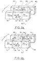
- FIG. 2a is a schematic representation of a "symmetric DMR" segment comprising MR elements 36,38 having active central regions 32,34 equal to the DMR reproduce trackwidth W r .
- the schematically illustrated DMRs are shown without the spacer between the MR elements and without the sense current leads attached to the DMR's elements.
- the sections 42,46 of MR element 38, and the sections 40,44 of the MR element 36 are the regions of the DMR where the sense current leads, if they had been shown, would contact the MR elements.
- the resultant magnetizations 48, 50 and 52, 54 have longitudinal components that are mutually parallel. Because the leads to the MR elements are of lower resistance than the MR elements themselves, and carry most of the current in the regions 42,46 and 52, 54 there is little mutual transverse biasing in these regions, and the magnetizations remain mostly longitudinally oriented. However, in the central active regions of the elements 36,38 the mutual biasing action described above results in the rotation of the magnetization 56 of the region 34 is one direction, and the magnetization 58 of the region 32 an approximately equal amount in the opposite direction.
- the signal response of the active regions of the MR elements of the present invention is predominantly by flux propagation through the MR element. It is known in the art that such flux propagation preferentially take place along paths that are perpendicular to the bias magnetization direction.
- flux entering the MR element 36 tends to propagate along the direction 60 perpendicular to the magnetization 58, while flux entering the MR element 38 tends to propagate along the direction 62 perpendicular to the magnetization 56.
- the preferred flux propagation paths for the two elements lie at roughly right angles to each other. This is of critical importance in the determination of the "symmetric" DMR's signal response, as will be explained infra.
- FIG. 2b the corresponding schematic representation of an "asymmetric" DMR is shown.
- the DMR of Fig. 2b is geometrically the same as that of Fig. 2a, consisting of corresponding MR elements 64,66 having end regions 68,70 and 72,74 respectively, and central active regions 76,78 equal to the track width W r .
- the elements are biased such that the longitudinal components of the bias magnetizations are anti-parallel.
- transverse biasing rotates the magnetization vectors 80, 82 in the central active regions 76,78 as previously described.
- the magnetizations 84,86,88,90 in the end regions 68,70,72,74 are not rotated much, as explained above.
- the magnetization vectors 80, 82 are positioned anti-parallel to each other, unlike the symmetric DMR where they are roughly perpendicular to each other.
- the favored flux propagation paths 92,94 perpendicular to the magnetization vectors 80,82 are now approximately parallel rather than perpendicular to each other.
- the different propagation path directions of the symmetric and asymmetric configurations result in differing signal response characteristics.
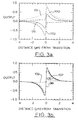
- the theoretically computed, linearized response of the symmetric DMR to an isolated recorded transition is plotted as curve 96, and the corresponding response for the asymmetric DMR is plotted as curve 98. Comparing the amplitudes of the two responses 96,98 it is seen that the asymmetric DMR has an on-track output more than twice the magnitude of the symmetric DMR's output. Use of the asymmetric DMR is therefore preferable in a high density recording application where the playback signal amplitude is of primary concern.
- the shape and amplitude of the asymmetric DMR waveform 98 is also found to be much less sensitive to variation in tracking offset than is the case of the symmetric DMR waveform 96; curves 105 and 107 for offsets of -0.5 micron and +0.5 micron offsets respectively differ very little from the on-track response 98.
- This difference in offset sensitivities is further indicated by the waveform 101 for the symmetric DMR and the waveform 109 for the asymmetric DMR.
- These waveforms illustrate head response to an isolated transition recorded on an adjacent track (i.e., with the head displaced 3 microns from being directly on-track) for a reproduce trackwidth of 2 microns and a 3 micron recorded track.
- the amplitude of the waveform 101 shows that the symmetric DMR has considerably more adjacent track side-reading than does the asymmetric DMR, as shown in waveform 109.
- the asymmetric DMR may be considered superior to the symmetric DMR.
- the otherwise inferior characteristics of the symmetric DMR could possibly provide a unique advantage in special applications where in addition to reproducing the recorded data, the head is servoed to the recorded track by means of positioning information derived from the same playback signal.
- the curve 100 shows the response of the symmetric DMR of the invention when it is offset from centering on the recorded track by +0.5 microns
- the curve 102 shows the response when offset by -0.5 microns.
- the sign and amplitude of the symmetric DMR playback signal may attendantly be used in generating position error information to servo the reproduce head into coincidence with the recorded track, in a manner known in the art. It is the low frequency component of the signal that provides the tracking information, and the high frequency component that provides the data information. Hence, the two components may be separated by means of appropriate filtering so that the tracking and data information may be recovered and processed in their individual channels.
- a symmetric DMR 103 comprises MR elements 104,106 separated by a conductive spacer 108 and having current leads 110,112 and a biasing magnet 116, as generally disclosed in U.S. Patent 5,084,794.
- the active region 114 of the DMR lies between the ends of the current leads 110,112, and the width of the active region 114 defines the track width, W r of the DMR as a reproduce head.
- the height of the MR elements 104,106 and the spacer 108 are each 2 microns and the active region width 114, i.e.
- the DMR's track width is also 2 microns, and in accordance with the teachings of the invention, the track width W r is less than 10 times the height of the MR elements 104,106.
- the MR elements 104,106 are .025 microns thick, and the spacer 108 has a thickness of 0.1 microns.
- the longitudinal bias required in a symmetric DMR of the above dimensions is generated by a "C" shaped magnet 116 located adjacent to the MR elements 104,106.
- the magnet 116 may be configured to provide a purely longitudinal field 118 directed along the longitudinal axes of the MR elements 104,106 by setting its magnetization 120 longitudinally in the manner taught in U.S.Patent 4,972,284, which is hereby incorporated by reference. Resultantly, the longitudinal magnetizations 121, 123 of the MR elements 106,104 respectively, are aligned in the same direction.
- the asymmetric DMR of Fig. 4b comprises MR elements 122, 124, spacer 126 and leads 128,130 as described for the symmetric DMR supra.
- the active region 132 of the asymmetric DMR lies between the ends of the current leads 128, 130 and the width of the active region 132 defines the track width, W r' of the asymmetric DMR as a reproduce head.
- the height of the MR elements 122, 126 and the spacer 124 are each 2 microns and the active region width 132, i.e.
- the asymmetric DMR's track width is also 2 microns, and in accordance with the teachings of the invention, the track width W r' is less than 10 times the height of the MR elements 122,126.
- the MR elements 122, 126 are .025 microns thick, and the spacer 124 has a thickness of 0.1 microns.
- the longitudinal magnetizations 134, 136 of the MR elements 122, 126 are oriented in opposite directions by means of the following longitudinal biasing technique.
- the magnetization 134, 136 of the MR elements 122, 126 are "pinned" at the ends of the element by use of patterned exchange biasing. This technique is described in the article "Unshielded MR Elements with Patterned Exchange Biasing", C. Tsang, IEEE Transactions on Magnetics, Vol. 25, No.5, September 1989, pp. 3692-3694.
- patterned exchange layers 138, 140 of FeMn in a thickness of approximately 100 angstroms are deposited over the "ends " of the MR element 122. Either during the FeMn deposition, or after annealing, a longitudinal magnetic field applied to the structure orients the resultant exchange bias field in the selected longitudinal direction.
- the spacer 124 is then deposited over the MR element 122 and the exchange layers 138,140, followed by the deposition of the second MR element 126.
- a second set of patterned exchange layers 142, 144 of TbCo are deposited.
- TbCo as an exchange biasing layer in conjunction with a magnetoresistive layer
- the thickness of the TbCo layers 142, 144 may be equal to or greater than 1000 angstroms.
- the sense current leads 128, 130 are then deposited, completing the deposition of the asymmetric DMR head.
- the TbCo layers can be deposited in the same magnetic field present during the deposition of the FeMn layers, and the completed DMR is then subjected to a "post-deposition" field in the opposite direction relative to the deposition field.
- This field switches the ferrimagnetic TbCo layers 142,144 and the MR layer 126 magnetization direction from the original direction of the magnetization 134 of the element 122.
- the magnetization 134 will also switch under the action of this "post-deposition” field, but on the removal of the "post-deposition” field the magnetization 134 will again reverse under the urging of the non- switchable anti-ferromagnetic exchange layers FeMn layers, 138,140.
- the final magnetization directions 134, 136 will then be in opposite directions as shown in Fig. 4b.
Abstract
Description
- This invention relates to magnetic recording, and in particular to a dual magnetoresistive head (DMR) for reproducing short wavelength, very narrow trackwidth digital data.
- The trend in digital disk recording systems continues in the direction of higher areal recording densities. This trend provides increased efficiency in the use of the recording medium, and contributes to the overall compactness and reduction in size of current computers. At the present time, linear recording densities of 50 kilo flux changes per inch and track densities of 2500 tracks per inch result in readily available areal densities of 125 megabits per square inch.
- An important component in attaining higher areal densities has been the MR reproduce head utilized in conjunction with a inductive record head. Both shielded and unshielded single element MR heads are known in the art, and each configuration has its advantages and its limitations. However, both configurations provide advantages which include independence of output level on head/media velocity and optimization of the write and read functions of the combined inductive write/ MR read transducer.
- The dual MR head (DMR) having a pair of unshielded MR elements as disclosed in U.S. Patent 5,084,794 provides the additional advantages of ease of head fabrication, excellent short wavelength response, a self biasing characteristic, and freedom from MR element shorting problems present in other biased MR head configurations. U.S. Patent 5,084,794 is hereby incorporated by reference.
- Referring to Fig. 1, a
typical DMR 10 known in the prior art consists of two magnetically, electrically and geometrically matchedMR elements 12,14. In this DMR embodiment, theMR elements 12,14 are separated over substantially their entire lengths by an electricallyconductive spacer 16. A sense and biasingcurrent 22 flowing to thehead 10 vialeads MR elements 12,14 into twoequal currents MR elements 12,14 are identical; a small portion of the current 22 flows in thespacer 16. TheDMR 10 is shown in contact with amagnetic medium 11. - The thin
film MR elements 12,14 are rectangular in shape. This configuration results in the shape anisotropy of the MR film being directed along the longitudinal axis of the film, which is also the direction of its unbiased magnetization. Static bias fields generated by the flow of sense current rotate the magnetization from this axial direction, and the signals from the magnetic medium further modulate the angular position of the magnetization, changing the film resistance. Thecurrents MR elements 12,14 generate magnetic fields that result in the mutual biasing of theMR elements 12,14 because each of the MR elements, as well as being a field detection element, acts as a soft adjacent biasing layer for the other. The bias field HB atelement 12 due to this self- biasing mechanism, is equal in magnitude and opposite in sign to the bias field -HB at the element 14. In biasing theMR elements 12,14 the magnetic field HB rotates the magnetization of theMR element 12 in one direction, and the field -HB rotates the magnetization of the MR element 14 in the opposite direction. It will be noted that the biasing fields HB and -HB due to the sense current have essentially no longitudinal components; they solely lie along the height directions of theMR element 12,14. - The MR and DMR heads of the prior art have usually been characterized by track widths equal to or greater than 10 times the MR element height. For example, in the above referenced patent the disclosed DMR has a track width of 50 microns and an MR element height of 5 microns. This large ratio of longitudinal extension to height in the heads of the prior art means that operation of the head is essentially "two dimensional" in nature. That is, characteristics of the head operation are determined in the plane perpendicular to that of the longitudinal axis of the MR element, and neither the head sensitivity nor the signal fields from the recorded medium vary appreciably in the longitudinal direction over the active area of the MR element.
- For an understanding of the operation of the narrow track width DMR for use in short wavelength signal reproduction, it is advantageous to consider the general signal response mechanism of the MR elements. There are essentially two mechanisms for generation of the MR reproduce signal; 1) direct signal field coupling, and 2) surface-field coupling plus flux propagation. The former accounts for the circumstance when the average (that is, over the MR element active volume) magnetic field emanating from the recorded medium is sufficiently large to directly induce modulation of the MR element magnetization to be observable as magnetoresistive signal. At high ( or even at moderate) linear recording densities, the fields from the medium die off extremely rapidly over distances of the order of typical element heights, and the MR response is due predominately, if not exclusively, to the second mechanism. In this case, the fields from the medium, being essentially non-negligible only at the medium's surface, enter the MR element at the head/medium interface and this surface flux is then internally propagated up into and through the remainder of the MR element. It is this second mechanism which primarily determines the response of the DMR of the present invention to high recording density signals.
- The invention relates to a DMR having a narrow track width, defined as equal to or less than 10 times the height of its MR elements, for use in reproducing signals having short wavelengths, for example, greater than 100 kiloflux changes per inch. A storage device using a head in accordance with the invention, and having an element height and a reproduce track width each equal to 2 microns for reading a written trackwidth of 3 microns, and reproducing recorded signals of 150 kilobits per inch has an areal storage density of 1200 megabits per square inch; a density on the order of 10 times greater the density of the prior art.
- The track width reduction to less than 10 times the MR element height introduces new parameters into the determination of the DMR signal response. In particular, the directional sense of the magnetization vectors along the longitudinal axes of the two MR elements join with the bias field direction and the signal field direction in determining the head response; that is, the head's performance is now determined by its "three dimensional" characteristics, rather than the "two dimensional" characteristics as in the prior art.
- Referring to Figs. 2a, 2b the "three dimensional" dependence of the flux propagated signal response of the DMR of the invention is illustrated. Fig. 2a is a schematic representation of a "symmetric DMR" segment comprising
MR elements central regions 32,34 equal to the DMR reproduce trackwidth Wr . For clarity in illustrating the criticalness of longitudinal biasing characteristic of the present invention, the schematically illustrated DMRs are shown without the spacer between the MR elements and without the sense current leads attached to the DMR's elements. In Fig. 2a, thesections MR element 38, and thesections MR element 36 are the regions of the DMR where the sense current leads, if they had been shown, would contact the MR elements. If, for example, a longitudinal biasing field is applied in the same directions to theelements regions resultant magnetizations regions elements region 34 is one direction, and themagnetization 58 of the region 32 an approximately equal amount in the opposite direction. - As described supra, the signal response of the active regions of the MR elements of the present invention is predominantly by flux propagation through the MR element. It is known in the art that such flux propagation preferentially take place along paths that are perpendicular to the bias magnetization direction. In Fig. 2a flux entering the
MR element 36 tends to propagate along thedirection 60 perpendicular to themagnetization 58, while flux entering theMR element 38 tends to propagate along thedirection 62 perpendicular to the magnetization 56. Thus, in the "symmetric" DMR of the invention, the preferred flux propagation paths for the two elements lie at roughly right angles to each other. This is of critical importance in the determination of the "symmetric" DMR's signal response, as will be explained infra. - Referring now to Fig. 2b, the corresponding schematic representation of an "asymmetric" DMR is shown. The DMR of Fig. 2b is geometrically the same as that of Fig. 2a, consisting of corresponding MR elements 64,66 having
end regions active regions 76,78 equal to the track width Wr. However, in this case the elements are biased such that the longitudinal components of the bias magnetizations are anti-parallel. When sense current flows in the DMR, transverse biasing rotates the magnetization vectors 80, 82 in the centralactive regions 76,78 as previously described. (The magnetizations 84,86,88,90 in theend regions flux propagation paths - For the narrow track width DMR of the invention, the different propagation path directions of the symmetric and asymmetric configurations result in differing signal response characteristics. Referring to Figs. 3a, 3b the theoretically computed, linearized response of the symmetric DMR to an isolated recorded transition is plotted as
curve 96, and the corresponding response for the asymmetric DMR is plotted ascurve 98. Comparing the amplitudes of the tworesponses asymmetric DMR waveform 98 is also found to be much less sensitive to variation in tracking offset than is the case of thesymmetric DMR waveform 96;curves track response 98. This difference in offset sensitivities is further indicated by thewaveform 101 for the symmetric DMR and thewaveform 109 for the asymmetric DMR. These waveforms illustrate head response to an isolated transition recorded on an adjacent track (i.e., with the head displaced 3 microns from being directly on-track) for a reproduce trackwidth of 2 microns and a 3 micron recorded track. The amplitude of thewaveform 101 shows that the symmetric DMR has considerably more adjacent track side-reading than does the asymmetric DMR, as shown inwaveform 109. For the reasons of greater on-track signal, reduced sensitivity to tracking error, and lesser adjacent track side- read, the asymmetric DMR may be considered superior to the symmetric DMR. - However, the otherwise inferior characteristics of the symmetric DMR could possibly provide a unique advantage in special applications where in addition to reproducing the recorded data, the head is servoed to the recorded track by means of positioning information derived from the same playback signal. Referring again to Fig. 3a, the
curve 100 shows the response of the symmetric DMR of the invention when it is offset from centering on the recorded track by +0.5 microns, and thecurve 102 shows the response when offset by -0.5 microns. The sign and amplitude of the symmetric DMR playback signal may attendantly be used in generating position error information to servo the reproduce head into coincidence with the recorded track, in a manner known in the art. It is the low frequency component of the signal that provides the tracking information, and the high frequency component that provides the data information. Hence, the two components may be separated by means of appropriate filtering so that the tracking and data information may be recovered and processed in their individual channels. - The invention and the prior art will be describe with respect to the figures, of which:
- Fig.1 illustrates a dual magnetoresistive head known in the prior art,
- Figs. 2a and 2b are drawings showing the biasing of the symmetric DMR and antisymmetric DMR respectively,
- Figs. 3a and 3b are plots of the signal output of the symmetric DMR and antisymmetric DMR respectively, and
- Figs. 4a and 4b illustrate techniques for providing the longitudinal biasing of the symmetric DMR and the antisymmetric DMR respectively.
- Referring to Fig. 4a, in a first embodiment a
symmetric DMR 103 comprises MR elements 104,106 separated by aconductive spacer 108 and having current leads 110,112 and abiasing magnet 116, as generally disclosed in U.S. Patent 5,084,794. As described supra, theactive region 114 of the DMR lies between the ends of the current leads 110,112, and the width of theactive region 114 defines the track width, Wr of the DMR as a reproduce head. In this preferred embodiment the height of the MR elements 104,106 and thespacer 108 are each 2 microns and theactive region width 114, i.e. the DMR's track width, is also 2 microns, and in accordance with the teachings of the invention, the track width Wr is less than 10 times the height of the MR elements 104,106. The MR elements 104,106 are .025 microns thick, and thespacer 108 has a thickness of 0.1 microns. - The longitudinal bias required in a symmetric DMR of the above dimensions is generated by a "C" shaped
magnet 116 located adjacent to the MR elements 104,106. Themagnet 116 may be configured to provide a purelylongitudinal field 118 directed along the longitudinal axes of the MR elements 104,106 by setting itsmagnetization 120 longitudinally in the manner taught in U.S.Patent 4,972,284, which is hereby incorporated by reference.
Resultantly, thelongitudinal magnetizations - In a second embodiment of the invention, the asymmetric DMR of Fig. 4b comprises
MR elements spacer 126 and leads 128,130 as described for the symmetric DMR supra. As in the symmetric DMR, theactive region 132 of the asymmetric DMR lies between the ends of the current leads 128, 130 and the width of theactive region 132 defines the track width, Wr' of the asymmetric DMR as a reproduce head. In this embodiment the height of theMR elements spacer 124 are each 2 microns and theactive region width 132, i.e. the asymmetric DMR's track width, is also 2 microns, and in accordance with the teachings of the invention, the track width Wr' is less than 10 times the height of the MR elements 122,126. TheMR elements spacer 124 has a thickness of 0.1 microns. - To provided the biasing required for the asymmetric DMR as described supra, the
longitudinal magnetizations MR elements magnetization MR elements MR element 122 is deposited, patterned exchange layers 138, 140 of FeMn in a thickness of approximately 100 angstroms are deposited over the "ends " of theMR element 122. Either during the FeMn deposition, or after annealing, a longitudinal magnetic field applied to the structure orients the resultant exchange bias field in the selected longitudinal direction. Thespacer 124 is then deposited over theMR element 122 and the exchange layers 138,140, followed by the deposition of thesecond MR element 126. On the "ends" of theMR element 126, a second set of patterned exchange layers 142, 144 of TbCo are deposited. (The use of TbCo as an exchange biasing layer in conjunction with a magnetoresistive layer is described in the article "Micromagnetic Model of an Exchange Coupled Ni-TbCo Bi-layer", N. Smith, W.C. Cain, Journal of Applied Physics, Vol 69, 1991, p. 2471.) The thickness of the TbCo layers 142, 144 may be equal to or greater than 1000 angstroms. The sense current leads 128, 130 are then deposited, completing the deposition of the asymmetric DMR head. For ease of fabrication, the TbCo layers can be deposited in the same magnetic field present during the deposition of the FeMn layers, and the completed DMR is then subjected to a "post-deposition" field in the opposite direction relative to the deposition field. This field switches the ferrimagnetic TbCo layers 142,144 and theMR layer 126 magnetization direction from the original direction of themagnetization 134 of theelement 122. Themagnetization 134 will also switch under the action of this "post-deposition" field, but on the removal of the "post-deposition" field themagnetization 134 will again reverse under the urging of the non- switchable anti-ferromagnetic exchange layers FeMn layers, 138,140. Thefinal magnetization directions - The invention has been described in detail with particular reference to preferred embodiments thereof, but it will be understood that variations and modifications can be effected within the spirit and scope of the invention.
Claims (9)
- A magnetic head assembly for reproducing a track of magnetically recorded information, said head assembly comprising:a) first and second thin film magnetoresistive sensing elements, said first and said second magnetoresistive sensing elements each having a transverse height L and a longitudinally extending length, said first and said second magnetoresistive elements having first and second unbiased magnetizations oriented along said longitudinally extending length of said first and said second magnetoresistive elements respectively,b) spacer means sandwiched between said first and said second magnetoresistive sensing elements,c) transverse biasing means for biasing said first and said second magnetoresistive sensing elements aligned along said height L such that the transverse bias component aligned along said first magnetoresistive sensing element's height is anti- parallel to the transverse bias component aligned along said second magnetoresistive sensing element's height,d) longitudinal biasing means for biasing said first and said second magnetoresistive sensing element along said longitudinally extending lengths of said magnetoresistive sensing elements, wherein the longitudinal bias component of said first magnetoresistive sensing element is parallel to, and in the same direction as the longitudinal bias component of said second magnetoresistive sensing element, ande) said first magnetoresistive sensing element having a first active region of width Wr, said second magnetoresistive having a second active region of width Wr, wherein Wr is less than 1/10 of said height L and Wr is the track width of said head, and further wherein the magnetization in said first active region is biased by said transverse bias and said longitudinal bias of said first magnetoresistive element in a first direction and the magnetization in said second active region is biased by said transverse bias and said longitudinal bias of said second magnetoresistive element in a second direction, said second direction being perpendicular to said first direction.
- The magnetic head assembly of Claim 1 wherein said longitudinal biasing means is a permanent magnet.
- The magnetic head assembly of Claim 1 wherein said transverse biasing means comprises said first and said second magnetoresistive elements serving as soft adjacent layers for mutual transverse biasing of each other.
- The magnetic head assembly of Claim 1 for use as a combined data reproduce head and on-track indicating head, wherein said head assembly provides a signal output whose amplitude and sign is a measure of mistracking of said head relative to said track.
- The magnetic head assembly of Claim 1 having a track width equal to or less than 2 microns.
- A magnetic head assembly for reproducing a track of magnetically recorded information, said head assembly comprising:a) first and second thin film magnetoresistive sensing elements, said first and said second magnetoresistive sensing elements each having a transverse height L and a longitudinally extending length, said first and said second magnetoresistive elements having first and second unbiased magnetizations oriented along said longitudinally extending length of said first and said second magnetoresistive elements respectively,b) spacer means sandwiched between said first and said second magnetoresistive sensing elements,c) transverse biasing means for biasing said first and said second magnetoresistive sensing elements aligned along said height L such that the transverse bias component aligned along said first magnetoresistive sensing element's height is anti- parallel to the transverse bias component aligned along said second magnetoresistive sensing element's height,d) longitudinal biasing means for biasing said first and said second magnetoresistive sensing element along said longitudinally extending lengths of said magnetoresistive sensing elements, wherein the longitudinal bias component of said first magnetoresistive sensing element is anti-parallel to the longitudinal bias component of said second magnetoresistive sensing element, ande) said first magnetoresistive sensing element having a first active region of width Wr, said second magnetoresistive having a second active region of width Wr, wherein Wr is less than 1/10 of said height L and Wr is the track width of said head, and further wherein the magnetization in said first active region is biased by said transverse bias and said longitudinal bias of said first magnetoresistive element in a first direction and the magnetization in said second active region is biased by said transverse bias and said longitudinal bias of said second magnetoresistive element in a second direction, said second direction being parallel to said first direction.
- The magnetic head assembly of Claim 6 wherein said longitudinal biasing means comprises a first exchange biasing layer for longitudinally biasing said first magnetoresistive element, and a second exchange biasing layer for longitudinally biasing said second magnetoresistive layer.
- The magnetic head assembly of Claim 6 wherein said transverse biasing means comprises said first and said second magnetoresistive elements serving as soft adjacent layers for mutual transverse biasing of each other.
- The magnetic head assembly of Claim 6 having a track width equal to or less than 2 microns.
Applications Claiming Priority (2)
| Application Number | Priority Date | Filing Date | Title |
|---|---|---|---|
| US160563 | 1993-12-01 | ||
| US08/160,563 US5406433A (en) | 1993-12-01 | 1993-12-01 | Dual magnetoresistive head for reproducing very narrow track width short wavelength data |
Publications (2)
| Publication Number | Publication Date |
|---|---|
| EP0656620A2 true EP0656620A2 (en) | 1995-06-07 |
| EP0656620A3 EP0656620A3 (en) | 1996-01-31 |
Family
ID=22577407
Family Applications (1)
| Application Number | Title | Priority Date | Filing Date |
|---|---|---|---|
| EP94420327A Withdrawn EP0656620A3 (en) | 1993-12-01 | 1994-11-23 | Dual magnetoresistive head for reproducing very narrow track width short wavelength data. |
Country Status (3)
| Country | Link |
|---|---|
| US (1) | US5406433A (en) |
| EP (1) | EP0656620A3 (en) |
| JP (1) | JPH07192229A (en) |
Cited By (1)
| Publication number | Priority date | Publication date | Assignee | Title |
|---|---|---|---|---|
| US7573684B2 (en) | 2005-04-13 | 2009-08-11 | Seagate Technology Llc | Current-in-plane differential magnetic tri-layer sensor |
Families Citing this family (22)
| Publication number | Priority date | Publication date | Assignee | Title |
|---|---|---|---|---|
| JPH07192227A (en) * | 1993-12-28 | 1995-07-28 | Sony Corp | Magneto-resistance effect type magnetic head |
| EP0675554A1 (en) * | 1994-03-24 | 1995-10-04 | Nec Corporation | Magnetoresistive effect element |
| TW272283B (en) * | 1994-04-21 | 1996-03-11 | Ibm | |
| JPH0845027A (en) * | 1994-07-29 | 1996-02-16 | Fujitsu Ltd | Magneto-resistive element and its production |
| US5701222A (en) * | 1995-09-11 | 1997-12-23 | International Business Machines Corporation | Spin valve sensor with antiparallel magnetization of pinned layers |
| US5657191A (en) * | 1995-09-18 | 1997-08-12 | Read-Rite Corporation | Stabilization of giant magnetoresistive transducers |
| US5712612A (en) * | 1996-01-02 | 1998-01-27 | Hewlett-Packard Company | Tunneling ferrimagnetic magnetoresistive sensor |
| US5766780A (en) * | 1996-10-15 | 1998-06-16 | Seagate Technology, Inc. | Reversed order NIMN exchange biasing for dual magnetoresistive heads |
| US5721008A (en) * | 1996-10-15 | 1998-02-24 | Seagate Technology, Inc. | Method for controlling sensor-to-sensor alignment and material properties in a dual magnetoresistive sensor |
| US5783460A (en) * | 1996-10-25 | 1998-07-21 | Headway Technologies, Inc. | Method of making self-aligned dual stripe magnetoresistive (DRMR) head for high density recording |
| US5920980A (en) * | 1997-03-05 | 1999-07-13 | Headway Technologies, Inc. | Method of making a soft adjacent layer (SAL) magnetoresistive (MR) sensor element with electrically insulated soft adjacent layer (SAL) |
| KR100276771B1 (en) | 1998-01-16 | 2001-01-15 | 윤종용 | Magnetoresistive Head Unit of Hard Disk Drive |
| WO1999059145A1 (en) * | 1998-05-13 | 1999-11-18 | Storage Technology Corporation | Method for reading both high and low density signals with an mr head |
| US6278594B1 (en) * | 1998-10-13 | 2001-08-21 | Storage Technology Corporation | Dual element magnetoresistive read head with integral element stabilization |
| US6310751B1 (en) | 1998-10-30 | 2001-10-30 | Headway Technologies, Inc. | Anti-parallel longitudinal patterned exchange biased dual stripe magnetoresistive (DSMR) sensor element and method for fabrication thereof |
| US6230390B1 (en) | 1998-10-30 | 2001-05-15 | Headway Technologies, Inc. | Canted longitudinal patterned exchange biased dual-stripe magnetoresistive (DSMR) sensor element and method for fabrication thereof |
| JP2000149201A (en) | 1998-11-09 | 2000-05-30 | Hitachi Ltd | Magnetic memory reproducing device |
| US6469877B1 (en) | 1999-06-15 | 2002-10-22 | Read-Rite Corporation | Spin valve device with improved exchange layer defined track width and method of fabrication |
| US6308400B1 (en) | 1999-08-06 | 2001-10-30 | Headway Technologies, Inc. | Method for achieving anti-parallel exchange coupling with one biased layer having low coercivity |
| US6643103B1 (en) | 2000-01-05 | 2003-11-04 | Seagate Technology Llc | Very high linear resolution CPP differential dual spin valve magnetoresistive head |
| US6621664B1 (en) | 2000-02-28 | 2003-09-16 | Seagate Technology Llc | Perpendicular recording head having integrated read and write portions |
| US6714389B1 (en) * | 2000-11-01 | 2004-03-30 | Seagate Technology Llc | Digital magnetoresistive sensor with bias |
Citations (2)
| Publication number | Priority date | Publication date | Assignee | Title |
|---|---|---|---|---|
| US3860965A (en) * | 1973-10-04 | 1975-01-14 | Ibm | Magnetoresistive read head assembly having matched elements for common mode rejection |
| WO1990007774A1 (en) * | 1989-01-03 | 1990-07-12 | Eastman Kodak Company | Deposited permanent magnet for hard and easy axes biasing of a magnetoresistive head |
Family Cites Families (8)
| Publication number | Priority date | Publication date | Assignee | Title |
|---|---|---|---|---|
| US5081554A (en) * | 1987-04-01 | 1992-01-14 | Digital Equipment Corporation | Biasing conductor for MR head |
| US4878140A (en) * | 1988-06-21 | 1989-10-31 | Hewlett-Packard Company | Magneto-resistive sensor with opposing currents for reading perpendicularly recorded media |
| US5155642A (en) * | 1989-11-29 | 1992-10-13 | International Business Machines Corporation | Anisotropy configuration for longitudinally constrained magnetoresistive transducers |
| JPH07113664B2 (en) * | 1990-02-26 | 1995-12-06 | シャープ株式会社 | Superconducting magnetic field distribution measuring device |
| US5084794A (en) * | 1990-03-29 | 1992-01-28 | Eastman Kodak Company | Shorted dual element magnetoresistive reproduce head exhibiting high density signal amplification |
| US5155643A (en) * | 1990-10-30 | 1992-10-13 | Mars Incorporated | Unshielded horizontal magnetoresistive head and method of fabricating same |
| US5206590A (en) * | 1990-12-11 | 1993-04-27 | International Business Machines Corporation | Magnetoresistive sensor based on the spin valve effect |
| US5323285A (en) * | 1992-06-23 | 1994-06-21 | Eastman Kodak Company | Shielded dual element magnetoresistive reproduce head exhibiting high density signal amplification |
-
1993
- 1993-12-01 US US08/160,563 patent/US5406433A/en not_active Expired - Lifetime
-
1994
- 1994-11-23 EP EP94420327A patent/EP0656620A3/en not_active Withdrawn
- 1994-11-30 JP JP6296490A patent/JPH07192229A/en active Pending
Patent Citations (2)
| Publication number | Priority date | Publication date | Assignee | Title |
|---|---|---|---|---|
| US3860965A (en) * | 1973-10-04 | 1975-01-14 | Ibm | Magnetoresistive read head assembly having matched elements for common mode rejection |
| WO1990007774A1 (en) * | 1989-01-03 | 1990-07-12 | Eastman Kodak Company | Deposited permanent magnet for hard and easy axes biasing of a magnetoresistive head |
Non-Patent Citations (8)
| Title |
|---|
| IEEE TRANSACTIONS ON MAGNETICS, vol. 27, no. 6, November 1991 NEW YORK US, L. NIX ET AL. 'Micromagnetic Track Profile Asymmetries in Dual Magnetoresistive Heads' * |
| IEEE TRANSACTIONS ON MAGNETICS, vol. 27, no. 6, November 1991 NEW YORK US, pages 4698-4700, S. L. TOMLINSON ET AL. 'Modelling the Effects of Boundary Pinning in Magnetoresistive Elements' * |
| IEEE TRANSACTIONS ON MAGNETICS, vol. 28, no. 5, September 1992 NEW YORK US, pages 2292-2294, N. SMITH ET AL. 'Dual magnetoresistive head for very high density recording' * |
| IEEE TRANSACTIONS ON MAGNETICS, vol. 28, no. 5, September 1992 NEW YORK US, pages 2295-2297, N. SMITH ET AL. 'Analysis of a dual magnetoresistive head' * |
| IEEE TRANSACTIONS ON MAGNETICS, vol. 30, no. 2, March 1994 NEW YORK US, pages 303-308, XP 000473177 T. C. ANTHONY ET AL. 'Dual Stripe Magnetoresistive Heads for High Density Recording' * |
| IEEE TRANSACTIONS ON MAGNETICS, vol. 30, no. 2, March 1994 NEW YORK US, pages 388-393, XP 000473192 N. SMITH ET AL. 'Micromagnetic modeling of a narrow-track dual magnetoresistive head' * |
| IEEE TRANSACTIONS ON MAGNETICS, vol. MAG-18, no. 6, November 1982 NEW YORK US, pages 1155-1157, N. H. YEH 'Asymmetric crosstalk of magnetoresistive head' * |
| JOURNAL OF APPLIED PHYSICS, vol. 69, no. 8, 15 April 1991 NEW YORK US, pages 5402-5404, A. WALLASH ET AL. 'Dependance of magnetoresistive head readback characteristics on sensor height' * |
Cited By (1)
| Publication number | Priority date | Publication date | Assignee | Title |
|---|---|---|---|---|
| US7573684B2 (en) | 2005-04-13 | 2009-08-11 | Seagate Technology Llc | Current-in-plane differential magnetic tri-layer sensor |
Also Published As
| Publication number | Publication date |
|---|---|
| US5406433A (en) | 1995-04-11 |
| JPH07192229A (en) | 1995-07-28 |
| EP0656620A3 (en) | 1996-01-31 |
Similar Documents
| Publication | Publication Date | Title |
|---|---|---|
| US5406433A (en) | Dual magnetoresistive head for reproducing very narrow track width short wavelength data | |
| US5218497A (en) | Magnetic recording-reproducing apparatus and magnetoresistive head having two or more magnetoresistive films for use therewith | |
| US6243288B1 (en) | Giant magnetoresistive sensor, thin-film read/write head and magnetic recording apparatus using the sensor | |
| US6906898B2 (en) | Differential detection read sensor, thin film head for perpendicular magnetic recording and perpendicular magnetic recording apparatus | |
| KR100336733B1 (en) | Low moment/high coercivity pinned layer for magnetic tunnel junction sensors | |
| KR100259429B1 (en) | Spin valve sensor with enhanced magnetoresistance | |
| US6473275B1 (en) | Dual hybrid magnetic tunnel junction/giant magnetoresistive sensor | |
| US5729410A (en) | Magnetic tunnel junction device with longitudinal biasing | |
| US6903906B2 (en) | Magnetic head with a lamination stack to control the magnetic domain | |
| US20020085320A1 (en) | AP-pinned spin valve design using very thin Pt-Mn AFM layer | |
| US7016160B2 (en) | Differential CPP reader for perpendicular magnetic recording | |
| JP3551099B2 (en) | Thin-film magnetic head for magnetic tape device | |
| US8270122B2 (en) | Magnetic recording and reproducing device including a differential read head | |
| JP2924875B2 (en) | Magnetoresistive head | |
| JP3377710B2 (en) | Magnetoresistive device and magnetic sensor | |
| JPS6350768B2 (en) | ||
| KR0145034B1 (en) | Peak enhanced magnetoresistive read transducer | |
| US6583970B1 (en) | Magnetoresistive head device incorporating joints between magnetoresistive layer and sense current conductors | |
| JPH07176019A (en) | Flat magnetoresistance head | |
| EP0372420B1 (en) | Magnetic recording-reproducing apparatus and magnetoresistive head for use therewith | |
| JP2000011331A (en) | Magnetoresistive element and thin film magnetic head | |
| US5774309A (en) | Magnetic transducer and thin film magnetic head | |
| JPH10302203A (en) | Vertical magnetic recorder | |
| Maruyama et al. | A yoke magnetoresistive head for high track density recording | |
| JPH0528436A (en) | Magneto-resistance effect type head |
Legal Events
| Date | Code | Title | Description |
|---|---|---|---|
| PUAI | Public reference made under article 153(3) epc to a published international application that has entered the european phase |
Free format text: ORIGINAL CODE: 0009012 |
|
| AK | Designated contracting states |
Kind code of ref document: A2 Designated state(s): DE FR GB NL |
|
| PUAL | Search report despatched |
Free format text: ORIGINAL CODE: 0009013 |
|
| AK | Designated contracting states |
Kind code of ref document: A3 Designated state(s): DE FR GB NL |
|
| 17P | Request for examination filed |
Effective date: 19960622 |
|
| STAA | Information on the status of an ep patent application or granted ep patent |
Free format text: STATUS: THE APPLICATION HAS BEEN WITHDRAWN |
|
| 17Q | First examination report despatched |
Effective date: 19990104 |
|
| 18W | Application withdrawn |
Withdrawal date: 19990206 |