EP0656249B1 - Modular base for tile cutters - Google Patents
Modular base for tile cutters Download PDFInfo
- Publication number
- EP0656249B1 EP0656249B1 EP94113434A EP94113434A EP0656249B1 EP 0656249 B1 EP0656249 B1 EP 0656249B1 EP 94113434 A EP94113434 A EP 94113434A EP 94113434 A EP94113434 A EP 94113434A EP 0656249 B1 EP0656249 B1 EP 0656249B1
- Authority
- EP
- European Patent Office
- Prior art keywords
- base
- base according
- coupling
- interlocking
- modular
- Prior art date
- Legal status (The legal status is an assumption and is not a legal conclusion. Google has not performed a legal analysis and makes no representation as to the accuracy of the status listed.)
- Expired - Lifetime
Links
- 230000008878 coupling Effects 0.000 claims abstract description 7
- 238000010168 coupling process Methods 0.000 claims abstract description 7
- 238000005859 coupling reaction Methods 0.000 claims abstract description 7
- 230000006835 compression Effects 0.000 claims description 2
- 238000007906 compression Methods 0.000 claims description 2
- 238000001125 extrusion Methods 0.000 claims description 2
- 230000000284 resting effect Effects 0.000 claims 1
- 239000000463 material Substances 0.000 description 6
- 238000005520 cutting process Methods 0.000 description 2
- 239000004033 plastic Substances 0.000 description 2
- 229920003023 plastic Polymers 0.000 description 2
- 238000003825 pressing Methods 0.000 description 2
- 229910000838 Al alloy Inorganic materials 0.000 description 1
- 238000005266 casting Methods 0.000 description 1
- 230000000670 limiting effect Effects 0.000 description 1
- 238000004519 manufacturing process Methods 0.000 description 1
- 239000007769 metal material Substances 0.000 description 1
- 230000004048 modification Effects 0.000 description 1
- 238000012986 modification Methods 0.000 description 1
- 238000000465 moulding Methods 0.000 description 1
- 125000006850 spacer group Chemical group 0.000 description 1
Images

Classifications
-
- B—PERFORMING OPERATIONS; TRANSPORTING
- B28—WORKING CEMENT, CLAY, OR STONE
- B28D—WORKING STONE OR STONE-LIKE MATERIALS
- B28D1/00—Working stone or stone-like materials, e.g. brick, concrete or glass, not provided for elsewhere; Machines, devices, tools therefor
- B28D1/22—Working stone or stone-like materials, e.g. brick, concrete or glass, not provided for elsewhere; Machines, devices, tools therefor by cutting, e.g. incising
- B28D1/225—Working stone or stone-like materials, e.g. brick, concrete or glass, not provided for elsewhere; Machines, devices, tools therefor by cutting, e.g. incising for scoring or breaking, e.g. tiles
Definitions
- the present invention relates to a modular base for tile cutters.
- Bases for tile cutters are constituted by an elongated platform to which an upper median rib is longitudinally rigidly coupled: two posts are fixed to the ends of said rib and support a rail along which a slider is movably mounted; a wheel for cutting into the surface of the tile and a shoe for breaking the tile by pressing it (simultaneously on the two sides of the cutting line cut previously with the wheel) against the rib of the base are installed on said slider.
- EP-A-0 428 070 discloses a modular base as defined in the preamble of independent claim 1.
- the principal aim of the present invention is to obviate the above drawbacks of known devices; in other words, to provide a modular base for tile cutters which is extremely light and strong and does not entail the manufacture of a mold for each size.
- an object of the present invention is to achieve the above aim with a structure that is simple, relatively easy to execute in practice, safe in use, effective in operation and relatively cheap.
- the present invention provides a modular base for tile cutters, which is characterized in that it comprises an extruded hollow profiled element which is longitudinally provided with a median rib on one of its faces and has, along its lateral edges, interlocking joints for the coupling of optional lateral extensions.
- the reference numeral 1 generally designates a modular base for tile cutters according to the invention.
- the base 1 is constituted by an extruded hollow profiled element 2 made of a material such as aluminum alloys, in which there are an upper thick portion 3a and a lower thick portion 3b which are mutually joined by thin spacers 4, 5 and by stiffening elements 6, 7a, 7b.
- the profiled element is longitudinally provided with a median contrast rib 8 on its upper face and has, along the lateral edges of the stiffening elements 7, respective interlocking joints 9 for coupling optional lateral extensions 10: the rib 8 is longitudinally crossed by a triangular cavity 8a.
- the interlocking joints 9 are of the dovetail type, advantageously of the mortise kind.
- the profiled element 2 has longitudinal supporting ribs 11 at its center and sides in a downward region.
- the extensions 10 are also constituted by an upper thick portion 12a and by a lower thick portion 12b which are joined at their sides by stiffening elements 13 and 14; the stiffening element 13 has a longitudinal supporting rib 15 in a downward region, whereas the stiffening element 14 forms, on one side, a longitudinal dovetail tenon 16 suitable to couple to one of the interlocking joints 9: conveniently, the ends of the extensions are cut at 45 degrees so that the base, as a whole, is shaped like an elongated rectangle with rounded corners.
- closure elements 17 which can be fixed in a snap-together manner and are made of plastic material:
- the closure elements 17 have an elongated rod 18 which is centrally provided with a contoured ridge 19 suitable to rest against the rib 8 (the ridge 19 is centrally provided with a tooth that can interlock in the cavity 8a);
- the rod 18 has, at its sides, two extensions 20 which are inclined at 45 degrees and suitable to rest against the ends of the extensions 10, which are cut at 45 degrees.
- the rod 18 and the two extensions 20 have multiple pairs of lugs 21 which are suitable to fit against the upper and lower thick portions of the profiled element 2 and of the extensions.
- Two supports 24 are mounted at the two ends of the rib 8 and are manufactured by molding a material such as plastics for the rail along which the slider slides: the supports 24 comprise a footing 25 below which there is a fork 26 that lies astride the rib 8 and two shoes 27a, 27b which are crossed by respective holes 28 for screws for fixing to the profiled element 2: in an upward region, the supports 24 form the two arms 29 of a fork with holes 30 for screws for fixing the rail of the slider.
- At least two lateral secondary surfaces 31 are mounted above the base and are covered, in an upward region, by an optional mat 32 made of a material such as rubber: the secondary surfaces are rectangular, are arranged on either side of the rib 8, and have seats 33 for the heads 34 of modular feet 35 for connection to the base: the feet 35 are made of two parts, one of which is a lower stub 36 the expanded head 37 whereof is suitable to pass through a wide hole in the lower thick portion 3b and rest against the edges of a corresponding narrow hole 38 of the upper thick portion 3a: the other part of the feet is constituted by a pin 39 which has a head 34 and is crossed by a central seat 40 for a screw and is provided, in a downward region, with a portion which is cut into sectors, is shaped like a truncated cone, and is suitable to expand when the screw penetrates and to fix itself to the stub 36; in order to prevent rotation of the pin during the tightening of the screw, at the top of the stub there are two radial notches
- the rib 8 In order to vary the level of the top of the rib 8 it is possible to provide the rib 8 so that it can be removed, with an interlocking joint, for example of the dovetail type, at its base in order to couple to a corresponding longitudinal dovetail slot of the profiled element 2.
Landscapes
- Engineering & Computer Science (AREA)
- Mining & Mineral Resources (AREA)
- Mechanical Engineering (AREA)
- Processing Of Stones Or Stones Resemblance Materials (AREA)
- Press-Shaping Or Shaping Using Conveyers (AREA)
- Perforating, Stamping-Out Or Severing By Means Other Than Cutting (AREA)
- Floor Finish (AREA)
Abstract
Description
- The present invention relates to a modular base for tile cutters.
- Bases for tile cutters are constituted by an elongated platform to which an upper median rib is longitudinally rigidly coupled: two posts are fixed to the ends of said rib and support a rail along which a slider is movably mounted; a wheel for cutting into the surface of the tile and a shoe for breaking the tile by pressing it (simultaneously on the two sides of the cutting line cut previously with the wheel) against the rib of the base are installed on said slider.
- Known bases, which must be rather strong and relatively non-deformable, are usually manufactured by casting or by pressing metallic material: this entails the execution of a relatively large number of molds (practically one for each base size to be produced) and a considerable use of material which entails hardly negligible costs and weights.
- EP-A-0 428 070 discloses a modular base as defined in the preamble of
independent claim 1. - The principal aim of the present invention is to obviate the above drawbacks of known devices; in other words, to provide a modular base for tile cutters which is extremely light and strong and does not entail the manufacture of a mold for each size.
- Within the scope of this aim, an object of the present invention is to achieve the above aim with a structure that is simple, relatively easy to execute in practice, safe in use, effective in operation and relatively cheap.
- The present invention provides a modular base for tile cutters, which is characterized in that it comprises an extruded hollow profiled element which is longitudinally provided with a median rib on one of its faces and has, along its lateral edges, interlocking joints for the coupling of optional lateral extensions.
- The characteristics and advantages of the invention will become apparent and evident from the following detailed description of a preferred but not exclusive embodiment thereof, illustrated only by way of non-limitative example in the accompanying drawings, wherein:
- figure 1 is a partially sectional front view of a modular base for tile cutters according to the invention;
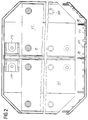
- figure 2 is a plan view of an end of the base of figure 1;
- figure 3 shows two views, in orthogonal projection, of a front closing element of the base.
-
- With particular reference to the above figures, the
reference numeral 1 generally designates a modular base for tile cutters according to the invention. - The
base 1 is constituted by an extruded hollow profiled element 2 made of a material such as aluminum alloys, in which there are an upperthick portion 3a and a lower thick portion 3b which are mutually joined bythin spacers 4, 5 and by stiffening elements 6, 7a, 7b. - The profiled element is longitudinally provided with a median contrast rib 8 on its upper face and has, along the lateral edges of the stiffening elements 7, respective interlocking joints 9 for coupling optional lateral extensions 10: the rib 8 is longitudinally crossed by a triangular cavity 8a.
- Conveniently, the interlocking joints 9 are of the dovetail type, advantageously of the mortise kind.
- The profiled element 2 has longitudinal supporting
ribs 11 at its center and sides in a downward region. - The
extensions 10 are also constituted by an upperthick portion 12a and by a lowerthick portion 12b which are joined at their sides bystiffening elements stiffening element 13 has a longitudinal supportingrib 15 in a downward region, whereas thestiffening element 14 forms, on one side, alongitudinal dovetail tenon 16 suitable to couple to one of the interlocking joints 9: conveniently, the ends of the extensions are cut at 45 degrees so that the base, as a whole, is shaped like an elongated rectangle with rounded corners. - The ends of the profiled
elements 2 and 10 are closed by two closure elements 17 which can be fixed in a snap-together manner and are made of plastic material: the closure elements 17 have anelongated rod 18 which is centrally provided with acontoured ridge 19 suitable to rest against the rib 8 (theridge 19 is centrally provided with a tooth that can interlock in the cavity 8a); therod 18 has, at its sides, twoextensions 20 which are inclined at 45 degrees and suitable to rest against the ends of theextensions 10, which are cut at 45 degrees. - The
rod 18 and the twoextensions 20 have multiple pairs oflugs 21 which are suitable to fit against the upper and lower thick portions of the profiled element 2 and of the extensions. - A certain number of
pins 22 of the expansion type, suitable to deform when a screw is tightened, is distributed on the closing elements 17; saidpins 22 are meant to fit incorresponding seats 23 formed by extrusion in the profiledelements 2 and 10; advantageously, the profiled element 2 has acentral seat 23 and two lateral seats, and the profiledelements 10 have one lateral seat each. - Two
supports 24 are mounted at the two ends of the rib 8 and are manufactured by molding a material such as plastics for the rail along which the slider slides: thesupports 24 comprise afooting 25 below which there is a fork 26 that lies astride the rib 8 and twoshoes 27a, 27b which are crossed byrespective holes 28 for screws for fixing to the profiled element 2: in an upward region, the supports 24 form the twoarms 29 of a fork withholes 30 for screws for fixing the rail of the slider. - At least two lateral
secondary surfaces 31 are mounted above the base and are covered, in an upward region, by anoptional mat 32 made of a material such as rubber: the secondary surfaces are rectangular, are arranged on either side of the rib 8, and haveseats 33 for theheads 34 ofmodular feet 35 for connection to the base: thefeet 35 are made of two parts, one of which is alower stub 36 the expanded head 37 whereof is suitable to pass through a wide hole in the lower thick portion 3b and rest against the edges of a correspondingnarrow hole 38 of the upperthick portion 3a: the other part of the feet is constituted by apin 39 which has ahead 34 and is crossed by acentral seat 40 for a screw and is provided, in a downward region, with a portion which is cut into sectors, is shaped like a truncated cone, and is suitable to expand when the screw penetrates and to fix itself to thestub 36; in order to prevent rotation of the pin during the tightening of the screw, at the top of the stub there are two radial notches 42, and corresponding ones are provided in the secondary surface; related radial wings of thepin 39 fit in said notches, and respectivehelical compression springs 43 are centered on thefeet 35 and press with their ends against the secondary surface and against the profiled element 2 and keep the secondary surface raised at a level that lies slightly above the rib 8: it is noted that the feet according to the invention accelerate and facilitate the operations for the assembly and optional disassembly of the secondary surfaces. - In order to vary the level of the top of the rib 8 it is possible to provide the rib 8 so that it can be removed, with an interlocking joint, for example of the dovetail type, at its base in order to couple to a corresponding longitudinal dovetail slot of the profiled element 2.
- It has thus been observed that the invention achieves the intended aim and object.
- The invention thus conceived is susceptible to numerous modifications and variations, all of which are within the scope of the appended claims.
- All the details may furthermore be replaced with other technically equivalent ones.
- In practice, the materials employed, as well as the shapes and dimensions, may be any according to the requirements without thereby abandoning the scope of the protection of the appended claims.
- Where technical features mentioned in any claim are followed by reference signs, those reference signs have been included for the sole purpose of increasing the intelligibility of the claims and accordingly such reference signs do not have any limiting effect on the scope of each element identified by way of example by such reference signs.
Claims (8)
- A modular base (1) for tile cutters, comprising an extruded hollow profiled element (2) which is longitudinally provided with a median rib (8) on one of its faces and has, along its lateral edges, connection means for the coupling of lateral extensions (10), characterized in that said connection means comprise interlocking joints (9) for the coupling of optional lateral extensions (10), said interlocking joints (9) extending along the full length of said lateral edges of the modular base.
- The base according to claim 1, characterized in that said interlocking joints (9) are of the dovetail type.
- The base according to claim 2, characterized in that said interlocking joints (9) are of the mortise kind.
- The base according to claim 1, characterized in that said profiled element (2) has, in a downward region, longitudinal resting ridges (11) at its center and sides.
- The base according to claim 1, characterized in that the ends of said profiled elements are closed by respective snap-on closure elements (17) which can be rigidly coupled to the profiled elements by means of screws which couple in respective seats (23) formed by extrusion.
- The base according to claim 1, characterized in that at least two lateral oscillating secondary surfaces (31) are mounted in an upward region on said base, said secondary surfaces being provided with modular feet (35) for connection to said base, helical compression springs being centered on said feet.
- The base according to claim 1, characterized in that said median rib (8) is removable and has, in a downward region, an interlocking coupling for a corresponding longitudinal slot of said profiled element (2).
- The base according to claim 7, characterized in that the interlocking coupling of said median rib is of the dovetail type.
Applications Claiming Priority (2)
| Application Number | Priority Date | Filing Date | Title |
|---|---|---|---|
| IT93BO000386A IT1264224B1 (en) | 1993-09-23 | 1993-09-23 | MODULAR BASE FOR TILE CUTTER |
| ITBO930386 | 1993-09-23 |
Publications (2)
| Publication Number | Publication Date |
|---|---|
| EP0656249A1 EP0656249A1 (en) | 1995-06-07 |
| EP0656249B1 true EP0656249B1 (en) | 2000-11-15 |
Family
ID=11339243
Family Applications (1)
| Application Number | Title | Priority Date | Filing Date |
|---|---|---|---|
| EP94113434A Expired - Lifetime EP0656249B1 (en) | 1993-09-23 | 1994-08-29 | Modular base for tile cutters |
Country Status (5)
| Country | Link |
|---|---|
| EP (1) | EP0656249B1 (en) |
| AT (1) | ATE197568T1 (en) |
| DE (1) | DE69426286T2 (en) |
| ES (1) | ES2151915T3 (en) |
| IT (1) | IT1264224B1 (en) |
Families Citing this family (3)
| Publication number | Priority date | Publication date | Assignee | Title |
|---|---|---|---|---|
| NL1033776C2 (en) * | 2007-04-27 | 2008-10-28 | Robo Beheer B V | Tile i.e. ceramic tile, cutting system, has two guides on which cutting and breaking mechanism moves in machine direction for cutting tile, and base including horizontal flat duct profile, which provides structural support function for tile |
| ES2545036B1 (en) * | 2014-02-07 | 2016-06-14 | Bellota Herramientas, S.A. | MODULAR MACHINE TO CUT CERAMIC PARTS |
| DE102014102965A1 (en) | 2014-03-06 | 2015-09-10 | Wolfcraft Gmbh | Tile cutter with a base frame having a support frame |
Family Cites Families (3)
| Publication number | Priority date | Publication date | Assignee | Title |
|---|---|---|---|---|
| GB1481135A (en) * | 1975-05-20 | 1977-07-27 | Brandon Enterprises Ltd | Tile cutters |
| ATE86539T1 (en) * | 1989-11-12 | 1993-03-15 | Kaufmann Gmbh & Co Kg | DEVICE FOR CUTTING TILES OR SLABS. |
| IT1253014B (en) * | 1991-09-09 | 1995-07-10 | Skc Di Tondini Claudio | WHEEL TILE CUTTER |
-
1993
- 1993-09-23 IT IT93BO000386A patent/IT1264224B1/en active IP Right Grant
-
1994
- 1994-08-29 DE DE69426286T patent/DE69426286T2/en not_active Expired - Fee Related
- 1994-08-29 AT AT94113434T patent/ATE197568T1/en not_active IP Right Cessation
- 1994-08-29 ES ES94113434T patent/ES2151915T3/en not_active Expired - Lifetime
- 1994-08-29 EP EP94113434A patent/EP0656249B1/en not_active Expired - Lifetime
Also Published As
| Publication number | Publication date |
|---|---|
| IT1264224B1 (en) | 1996-09-23 |
| DE69426286T2 (en) | 2001-04-12 |
| ITBO930386A0 (en) | 1993-09-23 |
| ITBO930386A1 (en) | 1995-03-23 |
| ATE197568T1 (en) | 2000-12-15 |
| EP0656249A1 (en) | 1995-06-07 |
| DE69426286D1 (en) | 2000-12-21 |
| ES2151915T3 (en) | 2001-01-16 |
Similar Documents
| Publication | Publication Date | Title |
|---|---|---|
| EP0437375B1 (en) | Method and apparatus for erecting a glass block wall | |
| US5761867A (en) | Tile support insert | |
| AU2014289215B2 (en) | Formwork panel for concreting formworks | |
| US6076807A (en) | Fence or deck post cap | |
| US5706625A (en) | Supportless dasher board | |
| US6513826B1 (en) | Device for connecting a snow glider to the boot of a person using a snow glider | |
| GB2118668A (en) | Window frames | |
| US3596918A (en) | Tapered tenon-type coupling device for connecting the elements of two-piece ski | |
| EP1426526B1 (en) | Formwork | |
| EP0656249A1 (en) | Modular base for tile cutters | |
| US2589517A (en) | Mounting for glass panels | |
| DE69807031D1 (en) | Railroad tie and sleeper shoe | |
| CA2170943C (en) | Supportless dasher board | |
| KR102336798B1 (en) | Cement block stand manufacturing apparatus for outdoor unit of air conditioner | |
| US4451032A (en) | Plastic ski slide | |
| JP3230107B2 (en) | Synthetic resin unit frame for building formwork | |
| US1079045A (en) | False work for concrete constructions. | |
| KR101879452B1 (en) | Gap Filling Member for Support-used Form | |
| JPH07224530A (en) | Corner part form | |
| JPS6118981Y2 (en) | ||
| KR102169180B1 (en) | Curb support | |
| JP2000317926A (en) | Form for manufacturing concrete slab, etc. | |
| JPH08112459A (en) | Starting block | |
| KR890007887Y1 (en) | Prefab Fruit Box | |
| JPH0237951Y2 (en) |
Legal Events
| Date | Code | Title | Description |
|---|---|---|---|
| PUAI | Public reference made under article 153(3) epc to a published international application that has entered the european phase |
Free format text: ORIGINAL CODE: 0009012 |
|
| AK | Designated contracting states |
Kind code of ref document: A1 Designated state(s): AT DE ES FR |
|
| 17P | Request for examination filed |
Effective date: 19951129 |
|
| 17Q | First examination report despatched |
Effective date: 19980717 |
|
| GRAG | Despatch of communication of intention to grant |
Free format text: ORIGINAL CODE: EPIDOS AGRA |
|
| GRAG | Despatch of communication of intention to grant |
Free format text: ORIGINAL CODE: EPIDOS AGRA |
|
| 17Q | First examination report despatched |
Effective date: 19980717 |
|
| GRAG | Despatch of communication of intention to grant |
Free format text: ORIGINAL CODE: EPIDOS AGRA |
|
| GRAH | Despatch of communication of intention to grant a patent |
Free format text: ORIGINAL CODE: EPIDOS IGRA |
|
| GRAH | Despatch of communication of intention to grant a patent |
Free format text: ORIGINAL CODE: EPIDOS IGRA |
|
| GRAA | (expected) grant |
Free format text: ORIGINAL CODE: 0009210 |
|
| AK | Designated contracting states |
Kind code of ref document: B1 Designated state(s): AT DE ES FR |
|
| REF | Corresponds to: |
Ref document number: 197568 Country of ref document: AT Date of ref document: 20001215 Kind code of ref document: T |
|
| REF | Corresponds to: |
Ref document number: 69426286 Country of ref document: DE Date of ref document: 20001221 |
|
| ET | Fr: translation filed | ||
| REG | Reference to a national code |
Ref country code: ES Ref legal event code: FG2A Ref document number: 2151915 Country of ref document: ES Kind code of ref document: T3 |
|
| PLBE | No opposition filed within time limit |
Free format text: ORIGINAL CODE: 0009261 |
|
| STAA | Information on the status of an ep patent application or granted ep patent |
Free format text: STATUS: NO OPPOSITION FILED WITHIN TIME LIMIT |
|
| 26N | No opposition filed | ||
| PGFP | Annual fee paid to national office [announced via postgrant information from national office to epo] |
Ref country code: FR Payment date: 20020724 Year of fee payment: 9 |
|
| PGFP | Annual fee paid to national office [announced via postgrant information from national office to epo] |
Ref country code: DE Payment date: 20020802 Year of fee payment: 9 |
|
| PGFP | Annual fee paid to national office [announced via postgrant information from national office to epo] |
Ref country code: ES Payment date: 20020821 Year of fee payment: 9 |
|
| PGFP | Annual fee paid to national office [announced via postgrant information from national office to epo] |
Ref country code: AT Payment date: 20020826 Year of fee payment: 9 |
|
| PG25 | Lapsed in a contracting state [announced via postgrant information from national office to epo] |
Ref country code: AT Free format text: LAPSE BECAUSE OF NON-PAYMENT OF DUE FEES Effective date: 20030829 |
|
| PG25 | Lapsed in a contracting state [announced via postgrant information from national office to epo] |
Ref country code: ES Free format text: LAPSE BECAUSE OF NON-PAYMENT OF DUE FEES Effective date: 20030830 |
|
| PG25 | Lapsed in a contracting state [announced via postgrant information from national office to epo] |
Ref country code: DE Free format text: LAPSE BECAUSE OF NON-PAYMENT OF DUE FEES Effective date: 20040302 |
|
| PG25 | Lapsed in a contracting state [announced via postgrant information from national office to epo] |
Ref country code: FR Free format text: LAPSE BECAUSE OF NON-PAYMENT OF DUE FEES Effective date: 20040430 |
|
| REG | Reference to a national code |
Ref country code: FR Ref legal event code: ST |
|
| REG | Reference to a national code |
Ref country code: ES Ref legal event code: FD2A Effective date: 20030830 |