EP0656229A1 - Pipette system - Google Patents
Pipette system Download PDFInfo
- Publication number
- EP0656229A1 EP0656229A1 EP94116687A EP94116687A EP0656229A1 EP 0656229 A1 EP0656229 A1 EP 0656229A1 EP 94116687 A EP94116687 A EP 94116687A EP 94116687 A EP94116687 A EP 94116687A EP 0656229 A1 EP0656229 A1 EP 0656229A1
- Authority
- EP
- European Patent Office
- Prior art keywords
- syringe
- gripping
- pipette
- piston
- devices
- Prior art date
- Legal status (The legal status is an assumption and is not a legal conclusion. Google has not performed a legal analysis and makes no representation as to the accuracy of the status listed.)
- Granted
Links
Images

Classifications
-
- B—PERFORMING OPERATIONS; TRANSPORTING
- B01—PHYSICAL OR CHEMICAL PROCESSES OR APPARATUS IN GENERAL
- B01L—CHEMICAL OR PHYSICAL LABORATORY APPARATUS FOR GENERAL USE
- B01L3/00—Containers or dishes for laboratory use, e.g. laboratory glassware; Droppers
- B01L3/02—Burettes; Pipettes
- B01L3/0275—Interchangeable or disposable dispensing tips
- B01L3/0279—Interchangeable or disposable dispensing tips co-operating with positive ejection means
-
- Y—GENERAL TAGGING OF NEW TECHNOLOGICAL DEVELOPMENTS; GENERAL TAGGING OF CROSS-SECTIONAL TECHNOLOGIES SPANNING OVER SEVERAL SECTIONS OF THE IPC; TECHNICAL SUBJECTS COVERED BY FORMER USPC CROSS-REFERENCE ART COLLECTIONS [XRACs] AND DIGESTS
- Y10—TECHNICAL SUBJECTS COVERED BY FORMER USPC
- Y10T—TECHNICAL SUBJECTS COVERED BY FORMER US CLASSIFICATION
- Y10T403/00—Joints and connections
- Y10T403/70—Interfitted members
- Y10T403/7047—Radially interposed shim or bushing
- Y10T403/7051—Wedging or camming
- Y10T403/7052—Engaged by axial movement
Definitions
- the invention relates to a pipette system according to the preamble of claim 1.
- Pipette systems of the type mentioned at the outset are often designed as repeater or multipipette systems which allow the gradual dispensing of a liquid from a syringe.
- a repeater pipette system is known from DE-C2 29 26 691, which is directed in particular to the repeater mechanism of the repeater pipette. It also describes how to fix a syringe of the system to the repeater pipette.
- the syringe has a syringe flange, which from the side in an open on the side essential U-shaped groove can be used.
- An axial pressure spring fixes the syringe flange in the groove.
- an insert element is provided which receives an end section of the syringe plunger between two jaws.
- the jaws can be pressed against the syringe plunger by means of a flap-shaped clamping member, the actuating lever of which protrudes through an opening out of the housing.
- This syringe fixation has the disadvantage that the syringe must be handled to insert and couple the piston actuating device.
- the syringe is subject to high cleanliness requirements. It is already manufactured under clean room conditions and usually has to be sterile. Removal also requires touching the syringe, which can be associated with a risk from adhering liquid.
- a pipette system with a syringe which can be pushed axially into the fastening positions of receptacles with the syringe flange and syringe plunger.
- fastening devices in the form of first grippers and second grippers with slotted end sections are provided, which are snapped onto the flange of the syringe body and an annular section of the syringe plunger.
- the syringe body is first inserted into the first gripper and then the second gripper is pushed onto the pipette piston until it snaps on.
- the syringe is repelled by first pushing the syringe body out of the end section of the pipette by advancing the second gripper and expanding it on a spreading sleeve by advancing the end sections of the second gripper and releasing the syringe plunger.
- the elastic restoring forces of the slotted end sections must be overcome in order to attach or detach the syringe. These must be large enough that the syringe does not completely or partially slip out of its attachment when aspirating or dispensing liquid.
- the syringe can only be inserted and ejected when the syringe plunger is fully pushed in, because both processes require the second gripper to be advanced toward the syringe.
- the invention has for its object to provide a pipette system for manual actuation that facilitated and safe coupling of the syringe to the pipette and easier separation of the syringe from the pipette without the user having to touch it and has an expanded range of use.
- the flange receptacles and piston receptacles are each provided with an axial opening.
- the syringe with the fastening section and syringe plunger can be pushed in a pure axial movement through the axial openings directly into the fastening positions of the fastening section and syringe plunger.
- the fastening section and syringe plunger are fixed by radially adjustable gripping devices which, for example, grip a syringe flange of the syringe and a piston collar of the syringe plunger in the fastening positions.
- the pipette system ensures that the syringe and hand pipette can be connected to one another by a purely axial relative movement and can be separated from one another by actuating the fastening devices.
- the syringe can be held stationary, for example in a stand, so that only manipulations of the hand pipette are required for the connection and disconnection process.
- the gripping devices can be controlled automatically by the axial movement.
- the syringe can also be ejected by loosening the fastening device, for example under the influence of gravity. In any case, connecting and disconnecting the syringe and pipette no longer requires manipulation of the syringe. Contamination of the syringe and user are practically impossible.
- the pipette system is preferably designed as a repeater pipette system.
- the axis bearing of the gripping devices ensures that they hold the syringe positively and thus securely in the fastening positions on the fastening section and syringe plunger independently of a spring force to be overcome during insertion. If spring devices press the gripping devices into the fastening position, the spring forces can be selected in a user-friendly manner.
- the axially mounted gripping devices can in principle be actuated independently of the axial position of the displaceable receiving body in the pipette housing, so that fully or partially filled syringes can be attached to or separated from the hand pipette. According to the invention, this became a special one the pipette system that promotes manual use and enlarges the area of application.
- the fastening section or syringe plunger preferably abut stops in their receptacles and are fixed there by the gripping devices by reaching behind.
- the fastening section can have a syringe flange and the piston can have a piston collar.
- the gripping devices can be gripping levers.
- the syringe gripping lever can have a hook-shaped gripping end for reaching behind the fastening section.
- piston gripping levers with a wedge-shaped gripping end are preferably provided.
- the gripping levers can be designed with two arms, wherein they have a gripping arm and an actuating arm.
- the gripping devices can be pressed into the locking position by spring devices. Then syringe gripping levers can be pressed into their locking position by leaf springs fixed to the housing. Leg springs can be provided for piston gripping levers, which are guided on a pivot axis of the levers and press with one leg against the receiving body and with the other leg against the piston gripping lever.
- the arrangement of the syringe grip levers or piston grip levers in radial openings of pipette housing or receiving body facilitates their actuation from the outside.
- the syringe grip levers can have actuating arms which can be actuated manually from the outside. These actuating arms can carry contact points on the inside, for example unlocking cams, which can be pivoted against the actuating arms of the piston gripping levers in order to actuate them.
- the stop for the fastening section can be supported in the pipette housing via axially acting spring devices.
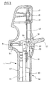
- a flange receptacle 5 for a syringe flange 6 of a syringe 7 is arranged in the lower end region of the lower housing part 2.
- the syringe 7 with its syringe body 8 protrudes from the lower housing part 2 through an axial opening 9 at the bottom.
- the top of the syringe flange 6 bears against a flange stop 10.
- the flange stop 10 is formed by two partially cylindrical halves, which are provided at the top with a radially outwardly projecting collar 11.
- An inner step 12 of the lower housing part 2 is assigned to the collar 11.
- Both halves of the flange stop 10 are supported by compression springs 13 on ring segments 14 which rest on the inner casing of the lower housing part 2 and are firmly connected to them.
- the compression springs 13 are designed as spiral springs and are guided on guide pins 15.
- the Guide pins 15 are anchored in the flange area of the flange stop 10 and guided in axial bores 16 of the ring segments 14.
- the flange stop 10 thus forms a spring-loaded abutment for the syringe flange 6.
- the syringe 7 is inserted with an outwardly projecting end section of a syringe plunger 17 into a plunger receptacle 18 of a receptacle body 19.
- the syringe plunger 17 projects into the receiving body 19 through an axial opening 20 of the plunger receptacle 18.
- the outer end of the syringe plunger 17 abuts against a plunger stop, which is formed by a bottom of the plunger receptacle 18.
- the receiving body 19 is fixed to a lifting rod 21 which forms a stop with its end in the piston receptacle 18 of the receiving body.
- the lifting rod 21 is fixedly connected to a sliding block 22 which is guided axially on the inner surface of the cylindrical section 3.
- the sliding block 22 carries a return movement lever 23 which protrudes from an axial slot 24 of the lower housing part 2.
- the receiving body 19 is axially displaceable in the lower housing part 2 by actuating the return movement lever 23.
- two syringe gripping levers 26 are mounted on pivot axes 27 in diametrically opposite openings 25 of the lower housing part.
- the syringe gripping levers 26 are provided with hook-shaped gripping ends 28 with which they can reach behind the underside of the syringe flange 6 when the latter rests against a lower annular stop section of the flange stop 10.
- the gripping levers 26 are arranged with a gripping arm 29 below the pivot axes 27 approximately in the region of the cone section 4 of the lower housing part 2.
- An actuating arm 30 of the gripping lever 26 above the pivot axes 27 is located in the cylindrical casing section 3 of the lower housing part 2.
- leaf springs 31 On the inner surface of the cylindrical shell section 3 there are two leaf springs 31 which are held at their upper end by an annular body 32 in the lower housing part 2. The lower end of the leaf springs 31 is angled outwards and presses against the inside of the gripping lever 26.
- the leaf springs 31 thus prestress the gripping levers 26 in the direction of the position engaging behind the syringe flange 6.
- the syringe grip levers 26 each carry an unlocking cam 33 on the inner sides of their actuating arms 30, which cam is directed towards the receiving body 19.
- the receiving body 19 is also provided with openings 34 on diametrically opposite sides.
- piston gripping levers 36 are mounted on pivot axes 35.
- the piston gripping levers 36 can engage behind a piston collar 37 at the outer end of the syringe piston 17.
- they have an approximately wedge-shaped gripping end 38, which is arranged above the pivot axis 35.
- Below the pivot axis 35 there is an actuating end 39 which tapers approximately wedge-shaped.
- the piston gripping levers 36 thus have an approximately diamond-like contour overall.
- the gripping levers 26, 36 each have lever arms of approximately the same length. However, the piston gripping levers 36 are shorter than the syringe gripping levers 26.
- each piston gripping lever 36 On the pivot axis 35 of each piston gripping lever 36 is one Leg spring 40 guided.
- the leg spring 40 is supported with the upper end on a stop pin 41, which is anchored in the receiving body 19.
- the other leg of the leg spring 40 has an end which is angled parallel to the pivot axis 35 and which engages in an outer step 42 of the actuating arm 39.
- the leg springs 40 bias the piston gripping levers 36 toward their position in which they engage behind the piston collar 37.
- the outside of the actuating arm 39 of the piston gripping lever 36 is shaped so that it is in this locking position in the pivoting range of the actuating cams 33 on the inside of the syringe gripping lever 26.
- the correct alignment of the piston gripping lever 36 with the syringe gripping lever 26 is ensured by guiding the return movement lever 23 in the axial slot 24.
- a syringe 7 can be accommodated in the repeater pipette 1 as follows: the syringe 7 is kept ready with its syringe flange 6 facing upwards.
- the syringe plunger 17 can be pressed as deep as possible into the syringe body 8.
- the receiving body 19 of the repeating pipette 1 is pressed as far as possible towards the flange receptacle 5.
- the axial movement is stopped by the return movement lever 23 against the lower end of the axial slot 24 limited. Then the repeating pipette 1 is inserted from above onto the upper end of the syringe 7 provided.
- the syringe flange 6 presses the syringe grip levers 26 outwards at their bevelled lower edges. In addition, the top of the syringe flange pushes the flange stop 10 upward. Finally, the hook-shaped gripping ends 28 of the syringe grip levers 26 snap behind the syringe flange 6 and fix this to the flange stop 10.
- the piston collar 37 presses the piston gripping levers 36 apart from the action of the leg spring 40 until it abuts against the bottom of the piston receptacle 18.
- the piston gripping levers 36 snap behind the piston collar 37 and fix this to the bottom of the piston receptacle 18.
- the syringe body 8 is locked in the repeater pipette 1 and the connection of the syringe plunger 17 to the lifting rod 21 and piston actuating devices coupled therewith is established.
- the syringe plunger 17 can be pulled further out of the syringe body 8 when it is connected to the receiving body 19. This is the case, for example, when a filled syringe is connected. In the locked position, the receiving body 19 is then at a corresponding distance from the syringe flange 6. The syringe plunger 17 can then be locked before, during or after the syringe flange 6 is locked.
- pipetting can be carried out by actuating the repeating mechanism. This will be discussed below.
- the syringe 7 can be released again.
- the syringe plunger 17 is pushed as far as possible into the syringe body 8
- only the actuation arms 30 of the two syringe gripping levers 26 are pressed inwards for this purpose, as is shown in the left half of FIG. 2.
- the gripper arms 28 release the syringe flange 6.
- the actuating cams 33 of the syringe grip levers 26 press against the actuating arms 39 of the Piston gripping lever 36 so that they release the piston collar 37. Then both syringe flange 6 and syringe plunger 17 are no longer held in their receptacles 5, 18.
- the preloaded spiral springs 13 press the flange stop 10 towards the axial opening 9 of the repeater pipette 1 in order to eject the syringe 7.
- the ejection movement of the flange stop 10 is limited by the stop of the collar 11 against the inner step 12 of the lower housing part 2.
- the flange gripping levers 26 can be released, whereupon the leaf springs 31 and the leg springs 40 move the syringe gripping levers 26 and the piston gripping levers 36 back into their locking position.
- the pipetting device is then ready for receiving another syringe 7.
- the plunger gripping levers 36 have to be moved into the pivoting range of the cams 33 when the syringe 7 is pulled out, so that the syringe plunger 17 can be separated from the receiving body 19.
- FIG. 3 This shows the repeating mechanism known from DE-C2-29 26 691, which is explained here only with regard to its basic structure and its basic functions.
- a housing upper part 43 of the repeating pipette 1 contains a toothed rack 44 which is firmly connected to the lifting rod 21 at the bottom (not shown).
- the toothing of the toothed rack 44 is assigned a cover 45 which is adjustable by means of a rotary knob 46.
- the rotary knob 46 has a guide curve 47 which interacts with a guide pin 48 which is fixed to the cover. By adjusting the rotary knob 46, the cover 45 with a lower end 49 can be more or less overlapped with a toothing 50 of the rack 44.
- a drive lever 52 is mounted in the upper housing part 43 on a pivot axis 51, on which in turn a pawl 53 is pivotably mounted.
- the drive lever 52 is pressed by a spring 54 into the position shown and the pawl 53 is biased towards the rack 44 by a tension spring 55.
- the drive lever 52 If the drive lever 52 is pressed down, it comes the pawl 53 with the teeth 50 of the rack 44 for engagement when it exceeds the lower end 47 of the cover 45.
- the setting of the cover 45 by means of the rotary knob 46 thus determines at which pivot angle of the drive lever 52 there is an engagement in the toothing 50 and thus a movement of the rack 44 downwards. Since the drive lever 52 is pressed down over its entire swivel path during each metering process, the position of the rotary knob 46 is decisive for the path covered thereby by the rack 44 and the fluid volume expelled thereby by the syringe 7.
- the rack has a protruding projection 56 at the top, which can push the cover 45 away at a shoulder 57, as a result of which further engagement of the pawl 53 in the toothing 50 is avoided and a residual stroke lock becomes effective.
- a repeating device 58 according to FIG. 3 forms, together with the return movement lever 23 of FIG. 1, piston actuating devices for displacing the receiving body 19 in the pipette housing.
Abstract
Description
Gegenstand der Erfindung ist ein Pipettensystem nach dem Oberbegriff des Anspruches 1.The invention relates to a pipette system according to the preamble of
Pipettensysteme der eingangs genannten Art sind häufig als Repetier- oder Multipipettensysteme ausgeführt, welche die schrittweise Abgabe einer Flüssigkeit aus einer Spritze ermöglichen. Ein solches Repetierpipettensystem ist aus der DE-C2 29 26 691 bekannt, die insbesondere auf den Repetiermechanismus der Repetierpipette gerichtet ist. Sie beschreibt auch die Fixierung einer Spritze des Systems an der Repetierpipette. Dafür hat die Spritze einen Spritzenflansch, der von der Seite her in eine seitlich offene, im wesentlichen U-förmige Nut einsetzbar ist. Eine axiale Andruckfeder fixiert den eingesetzten Spritzenflansch in der Nut. Für die Verbindung des Spritzenkolbens mit einer Kolbenstelleinrichtung ist ein Einsatzelement vorgesehen, welches einen Endabschnitt des Spritzenkolbens zwischen zwei Backen aufnimmt. Die Backen sind mittels eines klappenförmigen Klemmgliedes, dessen Betätigungshebel durch eine Öffnung aus dem Gehäuse herausragt, gegen den Spritzenkolben preßbar. Diese Spritzenfixierung hat den Nachteil, daß die Spritze zum Einsetzen und Koppeln der Kolbenstelleinrichtung angefaßt werden muß. An die Spritze werden jedoch hohe Sauberkeitsanforderungen gestellt. Sie wird bereits unter Reinraumbedingungen gefertigt und muß in der Regel steril sein. Auch die Entnahme erfordert ein Anfassen der Spritze, was mit einer Gefährdung durch anhaftende Flüssigkeit einhergehen kann.Pipette systems of the type mentioned at the outset are often designed as repeater or multipipette systems which allow the gradual dispensing of a liquid from a syringe. Such a repeater pipette system is known from DE-C2 29 26 691, which is directed in particular to the repeater mechanism of the repeater pipette. It also describes how to fix a syringe of the system to the repeater pipette. For this, the syringe has a syringe flange, which from the side in an open on the side essential U-shaped groove can be used. An axial pressure spring fixes the syringe flange in the groove. For the connection of the syringe plunger to a plunger actuating device, an insert element is provided which receives an end section of the syringe plunger between two jaws. The jaws can be pressed against the syringe plunger by means of a flap-shaped clamping member, the actuating lever of which protrudes through an opening out of the housing. This syringe fixation has the disadvantage that the syringe must be handled to insert and couple the piston actuating device. However, the syringe is subject to high cleanliness requirements. It is already manufactured under clean room conditions and usually has to be sterile. Removal also requires touching the syringe, which can be associated with a risk from adhering liquid.
Aus der CH 671 526 A5 und der EP 0 226 867 A2 ist ein Pipettensystem mit einer Spritze bekannt, die mit Spritzenflansch und Spritzenkolben axial in Befestigungspositionen von Aufnahmen schiebbar ist. Dafür sind Befestigungseinrichtungen in Form erster Greifer und zweiter Greifer mit geschlitzten Endabschnitten vorgesehen, die auf den Flansch des Spritzenkörpers und eines ringförmigen Abschnittes des Spritzenkolbens geschnappt werden. Hierzu wird zunächst der Spritzenkörper in den ersten Greifer eingesteckt und dann der zweite Greifer bis zum Aufschnappen auf den Pipettenkolben verschoben. Nach dem Pipettieren wird die Spritze abgestoßen, indem durch Vorschieben des zweiten Greifers zunächst der Spritzenkörper aus dem Endabschnitt der Pipette gedrückt und durch weiteres Vorschieben der Endabschnitte des zweiten Greifers an einer Spreizhülse aufgespreizt und der Spritzenkolben freigegeben wird.From CH 671 526 A5 and EP 0 226 867 A2 a pipette system with a syringe is known which can be pushed axially into the fastening positions of receptacles with the syringe flange and syringe plunger. For this purpose, fastening devices in the form of first grippers and second grippers with slotted end sections are provided, which are snapped onto the flange of the syringe body and an annular section of the syringe plunger. For this the syringe body is first inserted into the first gripper and then the second gripper is pushed onto the pipette piston until it snaps on. After pipetting, the syringe is repelled by first pushing the syringe body out of the end section of the pipette by advancing the second gripper and expanding it on a spreading sleeve by advancing the end sections of the second gripper and releasing the syringe plunger.
Bei dieser automatischen Vorrichtung müssen zum Befestigen bzw. Lösen der Spritze die elastischen Rückstellkräften der geschlitzten Endabschnitte überwunden werden. Diese müssen so groß sein, daß die Spritze beim Ansaugen oder Abgeben von Flüssigkeit nicht ganz oder teilweise aus ihrer Befestigung rutscht. Außerdem kann das Einsetzen und Abwerfen der Spritze nur bei vollständig eingedrücktem Spritzenkolben erfolgen, weil beide Vorgänge ein Vorschieben des zweiten Greifers zur Spritze hin Voraussetzen.With this automatic device, the elastic restoring forces of the slotted end sections must be overcome in order to attach or detach the syringe. These must be large enough that the syringe does not completely or partially slip out of its attachment when aspirating or dispensing liquid. In addition, the syringe can only be inserted and ejected when the syringe plunger is fully pushed in, because both processes require the second gripper to be advanced toward the syringe.
Die US 4 616 514 und die WO 93/15837 betreffen ebenfalls Systeme mit eigenelastischen Kupplungselementen.US 4 616 514 and WO 93/15837 also relate to systems with inherently elastic coupling elements.
Davon Ausgehend liegt der Erfindung die Aufgabe zugrunde, ein Pipettensystem für Handbetätigung zu schaffen, daß eine erleichterte und sichere Kopplung der Spritze mit der Pipette und eine erleichterte Trennung der Spritze von der Pipette ohne deren Anfassen durch den Anwender ermöglicht und einen erweiterten Einsatzbereich hat.Based on this, the invention has for its object to provide a pipette system for manual actuation that facilitated and safe coupling of the syringe to the pipette and easier separation of the syringe from the pipette without the user having to touch it and has an expanded range of use.
Die Lösung dieser Aufgabe ist in Anspruch 1 angegeben. Vorteilhafte Ausgestaltungen sind in den Unteransprüchen enthalten.The solution to this problem is specified in
Bei einem erfindungsgemäßen Pipettensystem sind die Flanschaufnahmen und Kolbenaufnahmen jeweils mit einer Axialöffnung versehen. Die Spritze ist mit Befestigungsabschnitt und Spritzenkolben in einer reinen Axialbewegung durch die Axialöffnungen unmittelbar bis in die Befestigungspositionen von Befestigungsabschnitt und Spritzenkolben schiebbar. Die Fixierung von Befestigungsabschnitt und Spritzenkolben erfolgt durch radial zustellbare Greifeinrichtungen, die z.B. einen Spritzenflansch der Spritze und einen Kolbenbund des Spritzenkolbens in den Befestigungspositionen ergreifen. Durch diese Merkmale des Pipettensystems wird erreicht, daß Spritze und Handpipette durch eine rein axiale Relativbewegung miteinander verbindbar und durch eine Betätigung der Befestigungseinrichtungen voneinander trennbar sind. Dabei kann die Spritze ortsfest gehalten werden, beispielsweise in einem Ständer, so daß für den Verbindungs- und Trennvorgang ausschließlich Manipulationen der Handpipette erforderlich sind. Beim Verbinden von Spritze und Handpipette können die Greifeinrichtungen durch die Axialbewegung automatisch gesteuert werden. Natürlich kann die Spritze durch Lösen der Befestigungseinrichtung beispielsweise unter Schwerkrafteinfluß auch abgeworfen werden. Jedenfalls erfordert das Verbinden und Trennen von Spritze und Handpipette keine Manipulation der Spritze mehr. Kontaminationen von Spritze und Benutzer sind damit praktisch ausgeschlossen. Das Pipettensystem ist vorzugsweise als Repetierpipettensystem ausgeführt.In a pipette system according to the invention, the flange receptacles and piston receptacles are each provided with an axial opening. The syringe with the fastening section and syringe plunger can be pushed in a pure axial movement through the axial openings directly into the fastening positions of the fastening section and syringe plunger. The fastening section and syringe plunger are fixed by radially adjustable gripping devices which, for example, grip a syringe flange of the syringe and a piston collar of the syringe plunger in the fastening positions. These features of the pipette system ensure that the syringe and hand pipette can be connected to one another by a purely axial relative movement and can be separated from one another by actuating the fastening devices. The syringe can be held stationary, for example in a stand, so that only manipulations of the hand pipette are required for the connection and disconnection process. When connecting the syringe and hand pipette, the gripping devices can be controlled automatically by the axial movement. Of course, the syringe can also be ejected by loosening the fastening device, for example under the influence of gravity. In any case, connecting and disconnecting the syringe and pipette no longer requires manipulation of the syringe. Contamination of the syringe and user are practically impossible. The pipette system is preferably designed as a repeater pipette system.
Durch die Achslagerung der Greifeinrichtungen wird erreicht, daß diese die Spritze in den Befestigungspositionen an Befestigungsabschnitt und Spritzenkolben unabhängig von einer beim Einschieben zu überwindenden Federkraft formschlüssig und damit sicher halten. Falls Federeinrichtungen die Greifeinrichtungen in die Befestigungsposition drücken, können die Federkräfte anwenderfreundlich gewählt werden. Hinzu kommt, daß die achsgelagerten Greifeinrichtungen grundsätzlich unabhängig von der Axialstellung des verschiebbaren Aufnahmekörpers im Pipettengehäuse betätigbar sind, so daß ganz oder teilweise gefüllte Spritzen an der Handpipette befestigbar bzw. von dieser trennbar sind. Erfindungsgemäß wurde somit ein besonders die Handbenutzung förderndes und den Einsatzbereich vergrößerndes Pipettensystem geschaffen.The axis bearing of the gripping devices ensures that they hold the syringe positively and thus securely in the fastening positions on the fastening section and syringe plunger independently of a spring force to be overcome during insertion. If spring devices press the gripping devices into the fastening position, the spring forces can be selected in a user-friendly manner. In addition, the axially mounted gripping devices can in principle be actuated independently of the axial position of the displaceable receiving body in the pipette housing, so that fully or partially filled syringes can be attached to or separated from the hand pipette. According to the invention, this became a special one the pipette system that promotes manual use and enlarges the area of application.
Bevorzugt stoßen Befestigungsabschnitt oder Spritzenkolben in ihren Aufnahmen gegen Anschläge und werden daran von den Greifeinrichtungen durch Hintergreifen fixiert. Dafür kann der Befestigungsabschnitt einen Spritzenflansch und der Kolben einen Kolbenbund aufweisen. Ferner können die Greifeinrichtungen Greifhebel sein. Dabei kann der Spritzengreifhebel ein hakenförmiges Greifende zum Hintergreifen des Befestigungsabschnittes haben. Zum Hintergreifen eines Kolbens sind bevorzugt Kolbengreifhebel mit einem keilförmigen Greifende vorgesehen. Die Greifhebel können zweiarmig ausgeführt sein, wobei sie einen Greifarm und einen Betätigungsarm aufweisen.The fastening section or syringe plunger preferably abut stops in their receptacles and are fixed there by the gripping devices by reaching behind. For this purpose, the fastening section can have a syringe flange and the piston can have a piston collar. Furthermore, the gripping devices can be gripping levers. The syringe gripping lever can have a hook-shaped gripping end for reaching behind the fastening section. For gripping behind a piston, piston gripping levers with a wedge-shaped gripping end are preferably provided. The gripping levers can be designed with two arms, wherein they have a gripping arm and an actuating arm.
Die Greifeinrichtungen können von Federeinrichtungen in Verriegelungsstellung gedrückt werden. Dann können Spritzengreifhebel von gehäusefesten Blattfedern in ihre Verriegelungsposition drückbar sein. Für Kolbengreifhebel können Schenkelfedern vorgesehen sein, die auf einer Schwenkachse der Hebel geführt sind und mit einem Schenkel gegen den Aufnahmekörper und mit dem anderen Schenkel gegen den Kolbengreifhebel drücken. Die Anordnung der Spritzengreifhebel bzw. Kolbengreifhebel in radialen Durchbrüchen von Pipettengehäuse bzw. Aufnahmekörper erleichtert deren Betätigung von außen. Dabei können die Spritzengreifhebel von außen manuell betätigbare Betätigungsarme haben. Diese Betätigungsarme können innen Kontaktstellen, z.B. Entriegelungsnocken tragen, die gegen die Betätigungsarme der Kolbengreifhebel schwenkbar sind, um diese zu betätigen.The gripping devices can be pressed into the locking position by spring devices. Then syringe gripping levers can be pressed into their locking position by leaf springs fixed to the housing. Leg springs can be provided for piston gripping levers, which are guided on a pivot axis of the levers and press with one leg against the receiving body and with the other leg against the piston gripping lever. The arrangement of the syringe grip levers or piston grip levers in radial openings of pipette housing or receiving body facilitates their actuation from the outside. The syringe grip levers can have actuating arms which can be actuated manually from the outside. These actuating arms can carry contact points on the inside, for example unlocking cams, which can be pivoted against the actuating arms of the piston gripping levers in order to actuate them.
Zum Toleranzausgleich und für einen selbsttätigen Abwurf der Spritze bei Lösen der Betätigungseinrichtungen kann der Anschlag für den Befestigungsabschnitt über axial wirkende Federeinrichtungen im Pipettengehäuse abgestützt sein.For tolerance compensation and for an automatic dropping of the syringe when the actuating devices are released, the stop for the fastening section can be supported in the pipette housing via axially acting spring devices.
Weitere Einzelheiten und Vorteile der Erfindung ergeben sich aus der nachfolgenden Beschreibung der zugehörigen Zeichnungen, die bevorzugte Ausführungsformen zeigen. In den Zeichnungen zeigen:
- Fig. 1
- Unterteil einer Repetierpipette mit Oberteil einer eingesetzten Spritze im Querschnitt (rechts vollständig, links teilweise eingesetzte Spritze);
- Fig. 2
- dasselbe Repetierpipettensystem in einem um 90° gedrehten Schnitt und betätigten Befestigungseinrichtungen (linke Hälfte) sowie unbetätigten Befestigungseinrichtungen (rechte Hälfte);
- Fig. 3
- Oberteil derselben Repetierpipette im Querschnitt.
- Fig. 1
- Cross section of the lower part of a repeater pipette with the upper part of an inserted syringe (complete right, partial syringe left);
- Fig. 2
- the same repeater pipette system in a cut rotated by 90 ° and actuated fastening devices (left half) and unactuated fastening devices (right half);
- Fig. 3
- Cross section of the top of the same repeater pipette.
Eine Repetierpipette 1 gemäß Fig. 1 und 2 hat ein Gehäuseunterteil 2 mit einem zylindrischen Mantelabschnitt 3 und einem Konusabschnitt 4 am unteren Ende ("unten" und "oben" bezieht sich stets auf die Ausrichtung der Vorrichtung(s-teile) in den Zeichnungen). Im unteren Endbereich des Gehäuseunterteiles 2 ist eine Flanschaufnahme 5 für einen Spritzenflansch 6 einer Spritze 7 angeordnet. Die Spritze 7 ragt mit ihrem Spritzenkörper 8 durch eine Axialöffnung 9 unten aus dem Gehäuseunterteil 2 heraus.1 and 2 has a
Der Spritzenflansch 6 liegt mit seiner Oberseite an einem Flanschanschlag 10 an. Der Flanschanschlag 10 wird von zwei teilzylindrischen Hälften gebildet, die oben mit einem radial nach außen vorstehenden Bund 11 versehen sind. Dem Bund 11 ist eine Innenstufe 12 des Gehäuseunterteiles 2 zugeordnet. Beide Hälften des Flanschanschlages 10 sind über Druckfedern 13 an Ringsegmenten 14 abgestützt, die am Innenmantel des Gehäuseunterteiles 2 anliegen und fest mit diesen verbunden sind. Die Druckfedern 13 sind als Spiralfedern ausgeführt und auf Führungsstiften 15 geführt. Die Führungsstifte 15 sind im Bundbereich des Flanschanschlages 10 verankert und in Axialbohrungen 16 der Ringsegmente 14 geführt.The top of the
Der Flanschanschlag 10 bildet somit für den Spritzenflansch 6 ein verfedertes Widerlager.The
Ferner ist die Spritze 7 mit einem nach außen ragenden Endabschnitt eines Spritzenkolbens 17 in eine Kolbenaufnahme 18 eines Aufnahmekörpers 19 eingesetzt. Dabei ragt der Spritzenkolben 17 durch eine Axialöffnung 20 der Kolbenaufnahme 18 in den Aufnahmekörper 19 hinein. Das äußere Ende des Spritzenkolbens 17 stößt gegen einen Kolbenanschlag, der von einem Boden der Kolbenaufnahme 18 gebildet wird.Furthermore, the
Der Aufnahmekörper 19 ist an einer Hubstange 21 fixiert, die mit ihrem Ende in der Kolbenaufnahme 18 des Aufnahmekörpers einen Anschlag bildet. Die Hubstange 21 ist fest mit einem Gleitblock 22 verbunden, der axial am Innenmantel des zylindrischen Abschnittes 3 geführt ist. Der Gleitblock 22 trägt einen Rückbewegungshebel 23, der aus einem Axialschlitz 24 des Gehäuseunterteiles 2 herausragt. Somit ist der Aufnahmekörper 19 durch Betätigung des Rückbewegungshebels 23 axial im Gehäuseunterteil 2 verschiebbar.The receiving
Zum Fixieren des Spritzenflansches 6 in der Flanschaufnahme 5 sind in einander diametral gegenüberliegenden Durchbrüchen 25 des Gehäuseunterteiles 2 Spritzengreifhebel 26 auf Schwenkachsen 27 gelagert. Die Spritzengreifhebel 26 sind mit hakenförmigen Greifenden 28 versehen, mit denen sie die Unterseite des Spritzenflansches 6 hintergreifen können, wenn dieser an einem unteren ringförmigen Anschlagabschnitt des Flanschanschlages 10 anliegt. Die Greifhebel 26 sind mit einem Greifarm 29 unterhalb der Schwenkachsen 27 etwa im Bereich des Konusabschnittes 4 des Gehäuseunterteiles 2 angeordnet. Ein Betätigungsarm 30 der Greifhebel 26 oberhalb der Schwenkachsen 27 befindet sich im zylindrischen Mantelabschnitt 3 des Gehäuseunterteiles 2. Somit schließt der Greifhebel 26, wenn er den Spritzenflansch 6 hintergreift, mit der Außenkontur des Konusabschnittes 4 ab und ist im Bereich des zylindrischen Abschnittes 3 an seinem Betätigungsarm 30 betätigbar.In order to fix the
Am Innenmantel des zylindrischen Mantelabschnittes 3 liegen zwei Blattfedern 31 an, die an ihrem oberen Ende von einem Ringkörper 32 im Gehäuseunterteil 2 gehalten sind. Das untere Ende der Blattfedern 31 ist nach außen abgewinkelt und drückt gegen die Innenseite der Greifhebel 26.On the inner surface of the
Durch die Blattfedern 31 werden also die Greifhebel 26 in Richtung auf die den Spritzenflansch 6 hintergreifende Position vorgespannt.The leaf springs 31 thus prestress the gripping
Die Spritzengreifhebel 26 tragen an den Innenseiten ihrer Betätigungsarme 30 jeweils einen Entriegelungsnocken 33, der zum Aufnahmekörper 19 gerichtet ist.The syringe grip levers 26 each carry an unlocking
Der Aufnahmekörper 19 ist ebenfalls an einander diametral gegenüberliegenden Seiten mit Durchbrüchen 34 versehen. In diesen Durchbrüchen 34 sind auf Schwenkachsen 35 Kolbengreifhebel 36 gelagert. Die Kolbengreifhebel 36 können einen Kolbenbund 37 am äußeren Ende des Spritzenkolbens 17 hintergreifen. Dafür haben sie ein etwa keilförmiges Greifende 38, welches oberhalb der Schwenkachse 35 angeordnet ist. Unterhalb der Schwenkachse 35 befindet sich ein Betätigungsende 39, welches sich annähernd keilförmig verjüngt. Die Kolbengreifhebel 36 haben somit insgesamt etwa eine rautenartige Kontur.The receiving
Die Greifhebel 26, 36 haben jeweils etwa gleich lange Hebelarme. Die Kolbengreifhebel 36 sind jedoch kürzer als die Spritzengreifhebel 26.The gripping levers 26, 36 each have lever arms of approximately the same length. However, the
Auf der Schwenkachse 35 jedes Kolbengreifhebels 36 ist eine Schenkelfeder 40 geführt. Die Schenkelfeder 40 ist mit dem oberen Ende an einem Anschlagstift 41 abgestützt, der im Aufnahmekörper 19 verankert ist. Der andere Schenkel der Schenkelfeder 40 hat ein parallel zur Schwenkachse 35 abgewinkeltes Ende, welches in eine Außenstufe 42 des Betätigungsarmes 39 eingreift. Die Schenkelfedern 40 spannen die Kolbengreifhebel 36 in Richtung auf ihre Position vor, in der sie den Kolbenbund 37 hintergreifen. Die Außenseite des Betätigungsarmes 39 der Kolbengreifhebel 36 ist so geformt, daß sie sich in dieser Verriegelungsposition im Schwenkbereich der Betätigungsnocken 33 an der Innenseite der Spritzengreifhebel 26 befindet. Die korrekte Ausrichtung der Kolbengreifhebel 36 auf die Spritzengreifhebel 26 wird durch die Führung des Rückbewegungshebels 23 in dem Axialschlitz 24 sichergestellt.On the
Die Aufnahme einer Spritze 7 in die Repetierpipette 1 kann folgendermaßen erfolgen: Die Spritze 7 wird mit ihrem Spritzenflansch 6 nach oben gerichtet bereitgehalten. Dabei kann der Spritzenkolben 17 so tief wie möglich in den Spritzenkörper 8 hineingedrückt sein. Mittels des Rückbewegungshebels 23 wird der Aufnahmekörper 19 der Repetierpipette 1 so weit wie möglich zur Flanschaufnahme 5 hin gedrückt. Die Axialbewegung wird durch Anschlag des Rückbewegungshebels 23 gegen das untere Ende des Axialschlitzes 24 begrenzt. Dann wird die Repetierpipette 1 von oben auf das obere Ende der bereitstehenden Spritze 7 gesteckt. Dabei drückt der Spritzenflansch 6 die Spritzengreifhebel 26 an ihren angeschrägten Unterkanten nach außen. Außerdem drückt die Oberseite des Spritzenflansches den Flanschanschlag 10 nach oben. Schließlich schnappen die hakenförmigen Greifenden 28 der Spritzengreifhebel 26 hinter dem Spritzenflansch 6 ein und legen diesen am Flanschanschlag 10 fest.A
Während des Einführens des Oberbereiches der Spritze 7 in die Repetierpipette 1 drückt der Kolbenbund 37 die Kolbengreifhebel 36 entgegen der Wirkung der Schenkelfeder 40 auseinander, bis er gegen den Boden der Kolbenaufnahme 18 stößt. Angetrieben von den Schenkelfedern 40 schnappen die Kolbengreifhebel 36 hinter dem Kolbenbund 37 ein und legen diesen am Boden der Kolbenaufnahme 18 fest. Danach ist der Spritzenkörper 8 in der Repetierpipette 1 verriegelt und ist die Verbindung des Spritzenkolbens 17 mit der Hubstange 21 und damit gekoppelten Kolbenstelleinrichtungen hergestellt.During the insertion of the upper region of the
Es ist auch möglich, zunächst den Spritzenflansch 6 zu verriegeln und danach den Spritzenkolben 17 mit dem Aufnahmekörper 19 zu verbinden. Hierzu kann der Aufnahmekörper 19 nach dem Verriegeln des Spritzenflansches 6 mittels des Rückbewegungshebels 23 in Verriegelungsposition über den Spritzenkolben 17 geschoben werden.It is also possible to first lock the
Ferner kann der Spritzenkolben 17 weiter aus dem Spritzenkörper 8 herausgezogen sein, wenn er mit dem Aufnahmekörper 19 verbunden wird. Dies ist beispielsweise bei Ankopplung einer befüllten Spritze der Fall. In Verriegelungsposition befindet sich der Aufnahmekörper 19 dann in einem entsprechenden Abstand vom Spritzenflansch 6. Die Verriegelung des Spritzenkolbens 17 kann dann vor, während oder nach der Verriegelung des Spritzenflansches 6 erfolgen.Furthermore, the
Nach dem Verriegeln der Spritze 7 an der Repetierpipette kann durch Betätigen des Repetiermechanismus pipettiert werden. Darauf wird unten noch eingegangen.After locking the
Nach dem Pipettieren kann die Spritze 7 wieder freigegeben werden. Wenn der Spritzenkolben 17 maximal in den Spritzenkörper 8 eingeschoben ist, werden hierfür lediglich die Betätigungsarme 30 der beiden Spritzengreifhebel 26 nach innen gedrückt, wie dies in der linken Hälfte von Fig. 2 gezeigt ist. Dabei geben deren Greifarme 28 den Spritzenflansch 6 frei. Zugleich drücken die Betätigungsnocken 33 der Spritzengreifhebel 26 gegen die Betätigungsarme 39 der Kolbengreifhebel 36, so daß diese den Kolbenbund 37 freigeben. Dann werden sowohl Spritzenflansch 6, als auch Spritzenkolben 17 nicht mehr in ihren Aufnahmen 5, 18 festgehalten. Zugleich drücken die vorgespannten Spiralfedern 13 den Flanschanschlag 10 zur Axialöffnung 9 der Repetierpipette 1 hin, um die Spritze 7 auszustoßen. Die Ausstoßbewegung des Flanschanschlages 10 wird durch den Anschlag des Bundes 11 gegen die Innenstufe 12 des Gehäuseunterteiles 2 begrenzt.After pipetting, the
Nach Freigabe der Spritze 7 können die Flanschgreifhebel 26 losgelassen werden, worauf die Blattfedern 31 und die Schenkelfedern 40 die Spritzengreifhebel 26 sowie die Kolbengreifhebel 36 in ihre Verriegelungsposition zurückbewegen. Die Pipettiervorrichtung ist dann für die Aufnahme einer weiteren Spritze 7 bereit.After the
Wenn der Spritzenkolben 17 bei Betätigung der Spritzengreifhebel 26 unvollständig in den Spritzenkörper 8 eintaucht, müssen die Kolbengreifhebel 36 beim Herausziehen der Spritze 7 in den Schwenkbereich der Nocken 33 bewegt werden, damit der Spritzenkolben 17 vom Aufnahmekörper 19 trennbar ist.If the
Zur Beschreibung eines Repetiermechanismus der Repetierpipette 1 wird auf die Fig. 3 Bezug genommen. Diese zeigt den aus der DE-C2-29 26 691 bekannten Repetiermechanismus, der hier nur hinsichtlich seines Grundaufbaues und seiner Grundfunktionen erläutert wird.To describe a repeater mechanism of the
Bei diesem Repetiermechanismus enthält ein Gehäuseoberteil 43 der Repetierpipette 1 eine Zahnstange 44, die unten fest mit der Hubstange 21 verbunden ist (nicht gezeigt). Der Zahnung der Zahnstange 44 ist eine Abdeckung 45 zugeordnet, welche mittels eines Drehknopfes 46 verstellbar ist. Dafür hat der Drehknopf 46 eine Führungskurve 47, die mit einem abdeckungsfesten Führungszapfen 48 zusammenwirkt. Durch Verstellen des Drehknopfes 46 kann die Abdeckung 45 mit einem unteren Ende 49 mehr oder weniger in Überdeckung mit einer Zahnung 50 der Zahnstange 44 gebracht werden.In this repeating mechanism, a housing
Ferner ist im Gehäuseoberteil 43 an einer Schwenkachse 51 ein Antriebshebel 52 gelagert, an dem wiederum eine Klinke 53 schwenkbar gelagert ist. Der Antriebshebel 52 wird von einer Feder 54 in die gezeichnete Stellung gedrückt und die Klinke 53 wird von einer Spannfeder 55 zur Zahnstange 44 hin vorgespannt.Furthermore, a
Wird der Antriebshebel 52 nach unten gedrückt, so kommt die Sperrklinke 53 mit der Zahnung 50 der Zahnstange 44 zum Eingriff, wenn sie das untere Ende 47 der Abdeckung 45 überschreitet. Die Einstellung der Abdeckung 45 mittels des Drehknopfes 46 bestimmt also, bei welchem Schwenkwinkel des Antriebshebels 52 ein Eingriff in die Zahnung 50 und damit eine Bewegung der Zahnstange 44 nach unten erfolgt. Da der Antriebshebel 52 bei jedem Dosiervorgang über seinen gesamten Schwenkweg nach unten gedrückt wird, ist die Position des Drehknopfes 46 bestimmend für den dabei von der Zahnstange 44 zurückgelegten Weg und das dabei von der Spritze 7 ausgestoßene Fluidvolumen. Bemerkenswert ist noch, daß die Zahnstange oben einen hochragenden Ansatz 56 aufweist, der die Abdeckung 45 an einer Absetzung 57 wegdrücken kann, wodurch ein weiterer Eingriff der Klinke 53 in die Zahnung 50 vermieden und eine Resthubsperre wirksam wird.If the
Eine Repetiervorrichtung 58 gemäß Fig. 3 bildet gemeinsam mit dem Rückbewegungshebel 23 der Fig. 1 Kolbenstelleinrichtungen zum Verschieben des Aufnahmekörpers 19 im Pipettengehäuse.A repeating
Claims (16)
Applications Claiming Priority (2)
| Application Number | Priority Date | Filing Date | Title |
|---|---|---|---|
| DE4341229A DE4341229C2 (en) | 1993-12-03 | 1993-12-03 | Pipette system |
| DE4341229 | 1993-12-03 |
Publications (2)
| Publication Number | Publication Date |
|---|---|
| EP0656229A1 true EP0656229A1 (en) | 1995-06-07 |
| EP0656229B1 EP0656229B1 (en) | 1997-07-16 |
Family
ID=6504100
Family Applications (1)
| Application Number | Title | Priority Date | Filing Date |
|---|---|---|---|
| EP94116687A Expired - Lifetime EP0656229B1 (en) | 1993-12-03 | 1994-10-22 | Pipette system |
Country Status (8)
| Country | Link |
|---|---|
| US (1) | US5620660A (en) |
| EP (1) | EP0656229B1 (en) |
| JP (1) | JP2673671B2 (en) |
| AT (1) | ATE155362T1 (en) |
| CA (1) | CA2136910C (en) |
| DE (2) | DE4341229C2 (en) |
| ES (1) | ES2105463T3 (en) |
| FI (1) | FI111228B (en) |
Cited By (13)
| Publication number | Priority date | Publication date | Assignee | Title |
|---|---|---|---|---|
| WO1996004991A1 (en) * | 1994-08-16 | 1996-02-22 | Marteau D Autry Eric | Pipette for distributing successive volumes of a liquid |
| WO2008107147A1 (en) * | 2007-03-02 | 2008-09-12 | Eppendorf Ag | Hand pipetting device |
| EP2033712A1 (en) * | 2007-09-05 | 2009-03-11 | Eppendorf AG | Pipette |
| EP2283927A1 (en) | 2006-05-23 | 2011-02-16 | Eppendorf Ag | Eletrical dosing apparatus for liquid |
| US8028592B2 (en) | 2006-08-09 | 2011-10-04 | Eppendorf Ag | Electronic metering apparatus for metering liquids |
| WO2014016282A1 (en) * | 2012-07-25 | 2014-01-30 | Hamilton Bonaduz Ag | Coupling formation of a pipetting channel of a pipetting device for coupling of a pipette tip thereto |
| US9289762B2 (en) | 2012-04-23 | 2016-03-22 | Eppendorf Ag | Method for dosing a liquid using a pipette and a syringe, and pipette for operating a syringe for dosing a liquid |
| US9579644B2 (en) | 2012-04-23 | 2017-02-28 | Eppendorf Ag | Pipette for operating a syringe |
| EP3260822A1 (en) | 2016-06-21 | 2017-12-27 | Eppendorf Ag | Multi-channel spray for use with a metering device |
| WO2018202725A1 (en) | 2017-05-05 | 2018-11-08 | Eppendorf Ag | Spindle drive |
| US10758899B2 (en) | 2017-05-05 | 2020-09-01 | Eppendorf Ag | Electronic dosing drive |
| US11154854B2 (en) | 2016-12-16 | 2021-10-26 | Eppendorf Ag | Method for dosing liquid by means of a pipette and a syringe, and pipette for actuating a syringe for dosing liquid |
| EP3928868A1 (en) | 2020-06-22 | 2021-12-29 | Eppendorf AG | Pipette for use with a pipette tip or syringe having a piston and a cylinder |
Families Citing this family (44)
| Publication number | Priority date | Publication date | Assignee | Title |
|---|---|---|---|---|
| DE19655129C2 (en) * | 1995-12-07 | 2001-03-08 | Walu Labortechnik Gmbh | Repeater pipette |
| EP0801309A3 (en) * | 1996-04-08 | 1998-08-12 | SANYO ELECTRIC Co., Ltd. | Pipetting apparatus |
| DE19626234A1 (en) * | 1996-06-29 | 1998-01-02 | Innova Gmbh | Device for the contamination-free supply and removal of liquids |
| DE19915066C2 (en) * | 1999-04-01 | 2001-09-13 | Brand Gmbh & Co Kg | Method for recognizing the type of exchangeable device-specific piston-cylinder units for pipetting or dosing devices as well as pipetting and dosing systems |
| DE19917907C2 (en) * | 1999-04-20 | 2001-08-16 | Brand Gmbh & Co Kg | Pipette for a pipette system |
| DE19963141A1 (en) | 1999-12-24 | 2001-07-12 | Brand Gmbh & Co Kg | Pipette for a pipetting system |
| EP1291658A1 (en) * | 2001-09-07 | 2003-03-12 | The Automation Partnership (Cambridge) Limited | Pipette head apparatus for robot |
| EP1438138B1 (en) * | 2001-10-16 | 2010-09-08 | Matrix Technologies Corporation | Hand-held pipettor |
| US20060027033A1 (en) * | 2002-10-16 | 2006-02-09 | Richard Cote | Hand-held pipette employing voice recognition control |
| US7284454B2 (en) * | 2004-05-27 | 2007-10-23 | Matrix Technologies Corporation | Hand held pipette |
| DE10257414B4 (en) * | 2002-12-05 | 2005-07-21 | Eppendorf Ag | Hand dispenser with electromotive drive |
| US7381371B2 (en) * | 2004-01-16 | 2008-06-03 | Heathrow Scientific Llc | Pipette device with pivotable nozzle assembly |
| US7641859B2 (en) * | 2004-02-11 | 2010-01-05 | Matrix Technologies Corporation | Pipette tip mounting and ejection assembly and associated pipette tip |
| EP1849012A2 (en) | 2005-01-28 | 2007-10-31 | Parker-Hannifin Corporation | Sampling probe, gripper and interface for laboratory sample management systems |
| DE102005023203B4 (en) * | 2005-05-20 | 2009-06-04 | Eppendorf Ag | pipette |
| DE102006009816A1 (en) | 2006-02-28 | 2007-09-06 | Eppendorf Ag | System and method for titrating liquids |
| US20080078258A1 (en) * | 2006-09-28 | 2008-04-03 | Price West L | Multi-component pipette tip and associated methods |
| WO2009038787A2 (en) * | 2007-09-19 | 2009-03-26 | Sorenson Bioscience, Inc. | Pipette tip rack and associated methods |
| US8277758B2 (en) * | 2007-11-08 | 2012-10-02 | Aea, S.R.L. | Assembly for actuating a syringe |
| US9211549B2 (en) | 2007-12-11 | 2015-12-15 | Tripath Imaging, Inc. | Sequential centrifuge |
| DE102009016590A1 (en) * | 2009-03-31 | 2010-10-07 | Eppendorf Ag | metering |
| DE102009034897A1 (en) | 2009-07-27 | 2011-02-03 | Eppendorf Ag | Syringe for use with dosing device that is utilized for e.g. receiving liquid, has cylindrical piston running portion connected with outlet, and coupling piece arranged at upper end of syringe piston for insertion into piston receiver |
| DE202009019205U1 (en) | 2009-07-27 | 2019-04-23 | Eppendorf Ag | Syringe, syringe family and dosing device |
| EP2279791B1 (en) | 2009-07-27 | 2014-11-12 | Eppendorf Ag | Nozzle, nozzle family and metering device |
| US8813584B2 (en) | 2009-07-27 | 2014-08-26 | Eppendorf Ag | Syringe, syringe family and metering device |
| DE102009051654B4 (en) | 2009-10-30 | 2013-01-03 | Eppendorf Ag | Dosing device for liquids and method for dosing liquids |
| DE202010009747U1 (en) | 2010-07-01 | 2010-11-18 | Brand Gmbh + Co Kg | Pipette for a pipette system with pipette and syringe |
| DE202010010942U1 (en) * | 2010-08-03 | 2011-11-08 | Brand Gmbh + Co Kg | Pipette for a pipette system with pipette and syringe |
| DE102010035891A1 (en) * | 2010-08-30 | 2012-03-01 | Eppendorf Ag | Syringe for use with a dosing device |
| US8632738B2 (en) * | 2010-08-30 | 2014-01-21 | Health Robotics S.r.l | Syringe actuating method and assembly |
| DE102011114688B4 (en) | 2011-10-04 | 2020-02-20 | Eppendorf Ag | manual proportioning device |
| PL2656916T3 (en) | 2012-04-23 | 2019-07-31 | Eppendorf Ag | Method for metering a liquid using a pipette and a syringe and pipette for actuating the syringe to dose the liquid |
| PL2656915T3 (en) | 2012-04-23 | 2019-04-30 | Eppendorf Ag | Pipette for actuating an injection |
| DE102012011938B4 (en) | 2012-06-18 | 2015-02-05 | Eppendorf Ag | Pipette for actuating a syringe |
| US8845578B2 (en) | 2013-02-28 | 2014-09-30 | Medtronic Xomed, Inc. | Biomaterial delivery device |
| US8920364B2 (en) | 2013-02-28 | 2014-12-30 | Medtronic Xomed, Inc. | Biomaterial delivery device |
| EP2783753B1 (en) | 2013-03-28 | 2017-02-22 | Eppendorf Ag | Dispenser for actuating an injection syringe |
| DE102014109345A1 (en) | 2014-07-04 | 2016-01-07 | Eppendorf Ag | Pipette for actuating a syringe |
| US10525460B2 (en) | 2016-06-15 | 2020-01-07 | Hamilton Company | Pipetting device, pipette tip coupler, and pipette tip: devices and methods |
| US11235318B2 (en) | 2016-06-15 | 2022-02-01 | Hamilton Company | Pipetting device, pipette tip coupler, and pipette tip: devices and methods |
| US10898892B2 (en) | 2016-06-15 | 2021-01-26 | Hamilton Company | Pipetting device, pipette tip coupler, and pipette tip: devices and methods |
| US11065614B2 (en) | 2016-06-15 | 2021-07-20 | Hamilton Company | Pipetting device, pipette tip coupler, and pipette tip: devices and methods |
| EP3477307B1 (en) * | 2017-10-24 | 2020-07-22 | F. Hoffmann-La Roche AG | Pipetting device and pipetting device positioning system |
| US11471878B2 (en) | 2019-10-25 | 2022-10-18 | Mettler-Toledo Rainin, LLC | Powered positive displacement pipette |
Citations (5)
| Publication number | Priority date | Publication date | Assignee | Title |
|---|---|---|---|---|
| US4249419A (en) * | 1979-01-05 | 1981-02-10 | Thomas Bradley S | Micropipette system |
| US4616514A (en) * | 1983-06-06 | 1986-10-14 | Rainin Instrument Co., Inc. | Replaceable tip assembly for pipette |
| EP0226867A2 (en) * | 1985-12-17 | 1987-07-01 | Hamilton Bonaduz AG | Pipette and pipetting system |
| EP0421785A2 (en) * | 1989-10-04 | 1991-04-10 | Drummond Scientific Company | Pipetter device |
| EP0603076A1 (en) * | 1992-12-18 | 1994-06-22 | Pasteur Sanofi Diagnostics | Syringe operating device, and automatic biological analyser incorporating such a device |
Family Cites Families (25)
| Publication number | Priority date | Publication date | Assignee | Title |
|---|---|---|---|---|
| DE2926691C2 (en) * | 1979-07-02 | 1983-05-26 | Eppendorf Gerätebau Netheler + Hinz GmbH, 2000 Hamburg | Repeater pipette |
| US4054062A (en) * | 1976-05-03 | 1977-10-18 | Oxford Laboratories Inc. | Hand-held micropipettor with improved accuracy of liquid volumes transferred |
| US4099548A (en) * | 1976-08-25 | 1978-07-11 | Oxford Laboratories Inc. | Hand-held pipette for repetitively dispensing precise volumes of liquid |
| FI57540C (en) * | 1977-02-17 | 1980-09-10 | Suovaniemi Finnpipette | ANORDNING FOER ATT LOESGOERA OCH AVLAEGSNA EN ENGAONGSSPETS PAO EN PIPETT |
| US4187724A (en) * | 1978-01-11 | 1980-02-12 | Indicon Inc. | Replaceable tip for a pipette |
| FI56937C (en) * | 1978-08-04 | 1980-05-12 | Suovaniemi Finnpipette | PIPETT ANORDNING FOER ATT AVLAEGSNA EN ENGAONGSSPETSBEHAOLLARE FRAON EN PIPETT |
| US4257267A (en) * | 1978-10-18 | 1981-03-24 | Bohr Scientific Corporation | Dispenser unit with lockable actuating lever |
| EP0022686A1 (en) * | 1979-07-16 | 1981-01-21 | COSMOS INVESTIGATIONS AND RESEARCH Société dite: | Spherical solar collector with simplified structure |
| JPS5919736B2 (en) * | 1981-02-09 | 1984-05-08 | 株式会社ニチリヨ− | pipetting device |
| US4418580A (en) * | 1981-10-13 | 1983-12-06 | Sherwood Medical Company | Pipettor mechanism and disposable tip and piston assembly |
| US4679446A (en) * | 1985-09-09 | 1987-07-14 | Baxter Travenol Laboratories, Inc. | Multi-volume displacement pipette |
| US4763535A (en) * | 1985-11-07 | 1988-08-16 | Rainin Instrument Co., Inc. | Pipette mechanism |
| DE3614085A1 (en) * | 1985-12-12 | 1987-06-19 | Hirschmann Glasgeraete | PIPETTE |
| US4744955A (en) * | 1986-08-08 | 1988-05-17 | Shapiro Justin J | Adjustable volume pipette sampler |
| DE3635598A1 (en) * | 1986-10-20 | 1988-05-05 | Eppendorf Geraetebau Netheler | PIPETTING DEVICE WITH A CLIP-ON CONE FOR A PIPETTE TIP AND PIPETTE TIP FOR SUCH A PIPETTING DEVICE |
| US5104624A (en) * | 1989-10-20 | 1992-04-14 | Costar Corporation | Pipetter |
| US5200151A (en) * | 1990-05-21 | 1993-04-06 | P B Diagnostic Systems, Inc. | Fluid dispensing system having a pipette assembly with preset tip locator |
| US5111703A (en) * | 1990-09-10 | 1992-05-12 | Eastman Kodak Company | Liquid aspirating pipette and dispensing system |
| US5143849A (en) * | 1991-03-21 | 1992-09-01 | Eastman Kodak Company | Tip to surface spacing for optimum dispensing controlled by a detected pressure change in the tip |
| US5213764A (en) * | 1991-05-15 | 1993-05-25 | Miles Inc. | Metering device for slide analysis system |
| FI88775C (en) * | 1992-02-11 | 1993-07-12 | Biohit Oy | Pipette |
| FI921648A0 (en) * | 1992-04-13 | 1992-04-13 | Labsystems Oy | STEGPIPETT. |
| FI922939A0 (en) * | 1992-06-24 | 1992-06-24 | Labsystems Oy | KNAPPIPETT. |
| US5249711A (en) * | 1992-10-01 | 1993-10-05 | Du Pont Canada Inc. | Disposable dispensing pipette |
| US5364596A (en) * | 1992-12-01 | 1994-11-15 | Rainin Instrument Co., Inc. | Manual pipette with plunger velocity governor, home position latch and trigger release |
-
1993
- 1993-12-03 DE DE4341229A patent/DE4341229C2/en not_active Expired - Lifetime
-
1994
- 1994-10-22 AT AT94116687T patent/ATE155362T1/en active
- 1994-10-22 DE DE59403385T patent/DE59403385D1/en not_active Expired - Lifetime
- 1994-10-22 EP EP94116687A patent/EP0656229B1/en not_active Expired - Lifetime
- 1994-10-22 ES ES94116687T patent/ES2105463T3/en not_active Expired - Lifetime
- 1994-11-28 US US08/345,671 patent/US5620660A/en not_active Expired - Lifetime
- 1994-11-29 CA CA002136910A patent/CA2136910C/en not_active Expired - Lifetime
- 1994-12-01 FI FI945661A patent/FI111228B/en not_active IP Right Cessation
- 1994-12-02 JP JP6329511A patent/JP2673671B2/en not_active Expired - Lifetime
Patent Citations (5)
| Publication number | Priority date | Publication date | Assignee | Title |
|---|---|---|---|---|
| US4249419A (en) * | 1979-01-05 | 1981-02-10 | Thomas Bradley S | Micropipette system |
| US4616514A (en) * | 1983-06-06 | 1986-10-14 | Rainin Instrument Co., Inc. | Replaceable tip assembly for pipette |
| EP0226867A2 (en) * | 1985-12-17 | 1987-07-01 | Hamilton Bonaduz AG | Pipette and pipetting system |
| EP0421785A2 (en) * | 1989-10-04 | 1991-04-10 | Drummond Scientific Company | Pipetter device |
| EP0603076A1 (en) * | 1992-12-18 | 1994-06-22 | Pasteur Sanofi Diagnostics | Syringe operating device, and automatic biological analyser incorporating such a device |
Cited By (18)
| Publication number | Priority date | Publication date | Assignee | Title |
|---|---|---|---|---|
| WO1996004991A1 (en) * | 1994-08-16 | 1996-02-22 | Marteau D Autry Eric | Pipette for distributing successive volumes of a liquid |
| US5770159A (en) * | 1994-08-16 | 1998-06-23 | Marteau D'autry; Eric | Pipette for dispensing successive volumes of liquid |
| EP2283927A1 (en) | 2006-05-23 | 2011-02-16 | Eppendorf Ag | Eletrical dosing apparatus for liquid |
| US8028592B2 (en) | 2006-08-09 | 2011-10-04 | Eppendorf Ag | Electronic metering apparatus for metering liquids |
| WO2008107147A1 (en) * | 2007-03-02 | 2008-09-12 | Eppendorf Ag | Hand pipetting device |
| EP2033712A1 (en) * | 2007-09-05 | 2009-03-11 | Eppendorf AG | Pipette |
| US9579644B2 (en) | 2012-04-23 | 2017-02-28 | Eppendorf Ag | Pipette for operating a syringe |
| US9289762B2 (en) | 2012-04-23 | 2016-03-22 | Eppendorf Ag | Method for dosing a liquid using a pipette and a syringe, and pipette for operating a syringe for dosing a liquid |
| US10906034B2 (en) | 2012-04-23 | 2021-02-02 | Eppendorf Ag | Method for dosing a liquid using a pipette and a syringe, and pipette for operating a syringe for dosing a liquid |
| WO2014016282A1 (en) * | 2012-07-25 | 2014-01-30 | Hamilton Bonaduz Ag | Coupling formation of a pipetting channel of a pipetting device for coupling of a pipette tip thereto |
| US9803789B2 (en) | 2012-07-25 | 2017-10-31 | Hamilton Bonaduz Ag | Coupling formation of a pipetting channel of a pipetting device for coupling of a pipette tip thereto |
| EP3260822A1 (en) | 2016-06-21 | 2017-12-27 | Eppendorf Ag | Multi-channel spray for use with a metering device |
| US11154854B2 (en) | 2016-12-16 | 2021-10-26 | Eppendorf Ag | Method for dosing liquid by means of a pipette and a syringe, and pipette for actuating a syringe for dosing liquid |
| US11697113B2 (en) | 2016-12-16 | 2023-07-11 | Eppendorf Ag | Method for dosing liquid by means of a pipette and a syringe, and pipette for actuating a syringe for dosing liquid |
| WO2018202725A1 (en) | 2017-05-05 | 2018-11-08 | Eppendorf Ag | Spindle drive |
| US10758899B2 (en) | 2017-05-05 | 2020-09-01 | Eppendorf Ag | Electronic dosing drive |
| US11280389B2 (en) | 2017-05-05 | 2022-03-22 | Eppendorf Ag | Spindle drive |
| EP3928868A1 (en) | 2020-06-22 | 2021-12-29 | Eppendorf AG | Pipette for use with a pipette tip or syringe having a piston and a cylinder |
Also Published As
| Publication number | Publication date |
|---|---|
| FI945661A0 (en) | 1994-12-01 |
| DE59403385D1 (en) | 1997-08-21 |
| EP0656229B1 (en) | 1997-07-16 |
| ATE155362T1 (en) | 1997-08-15 |
| FI945661A (en) | 1995-06-04 |
| JPH07194987A (en) | 1995-08-01 |
| DE4341229A1 (en) | 1995-06-08 |
| ES2105463T3 (en) | 1997-10-16 |
| FI111228B (en) | 2003-06-30 |
| CA2136910A1 (en) | 1995-06-04 |
| DE4341229C2 (en) | 1995-09-07 |
| CA2136910C (en) | 1999-11-23 |
| US5620660A (en) | 1997-04-15 |
| JP2673671B2 (en) | 1997-11-05 |
Similar Documents
| Publication | Publication Date | Title |
|---|---|---|
| EP0656229B1 (en) | Pipette system | |
| EP2033712B1 (en) | Pipette | |
| DE102005023203B4 (en) | pipette | |
| EP3169387B1 (en) | Safety needle arrangement for drawing liquid from a body | |
| DE60210735T2 (en) | Transfer device and system with a cap assembly, a container and the transfer device | |
| EP2313022B1 (en) | Connector for a discharge device | |
| EP1998901B1 (en) | Discharge arrangement with detachably fastenable accessory parts | |
| EP2121082B1 (en) | Single-use injector with at least one draw hook | |
| EP1974827B1 (en) | Dispensing device for fluids | |
| DE19739002A1 (en) | Axial handle for surgical, esp. endoscopic, instruments | |
| DE2845213B2 (en) | Device for setting surgical staples | |
| EP0885599B1 (en) | Application device | |
| DE4209529C1 (en) | ||
| WO1987001315A1 (en) | Process and device for driving blind rivets | |
| EP3680017A1 (en) | Pipette for use with a pipette tip | |
| EP0806187A2 (en) | Applicator | |
| WO2004075765A1 (en) | Surgical instrument | |
| WO1999004839A1 (en) | Injection device for dentists | |
| EP3073875B1 (en) | Beverage preparation device | |
| WO1998029054A1 (en) | Dosing pistol for use with dental cartridges | |
| EP4054447B1 (en) | Medical sliding shaft instrument | |
| EP3552988A1 (en) | Product dispenser and adapter for product dispenser | |
| EP0396561A1 (en) | Device for ligaturing parts of the body. | |
| DE3306524A1 (en) | DOSING DEVICE | |
| EP4058380B1 (en) | Waste container with blocking device and refill cartridge with unblocking element |
Legal Events
| Date | Code | Title | Description |
|---|---|---|---|
| PUAI | Public reference made under article 153(3) epc to a published international application that has entered the european phase |
Free format text: ORIGINAL CODE: 0009012 |
|
| 17P | Request for examination filed |
Effective date: 19941102 |
|
| AK | Designated contracting states |
Kind code of ref document: A1 Designated state(s): AT BE CH DE ES FR GB IT LI LU NL SE |
|
| 17Q | First examination report despatched |
Effective date: 19951222 |
|
| GRAG | Despatch of communication of intention to grant |
Free format text: ORIGINAL CODE: EPIDOS AGRA |
|
| GRAH | Despatch of communication of intention to grant a patent |
Free format text: ORIGINAL CODE: EPIDOS IGRA |
|
| GRAH | Despatch of communication of intention to grant a patent |
Free format text: ORIGINAL CODE: EPIDOS IGRA |
|
| GRAA | (expected) grant |
Free format text: ORIGINAL CODE: 0009210 |
|
| AK | Designated contracting states |
Kind code of ref document: B1 Designated state(s): AT BE CH DE ES FR GB IT LI LU NL SE |
|
| REF | Corresponds to: |
Ref document number: 155362 Country of ref document: AT Date of ref document: 19970815 Kind code of ref document: T |
|
| REG | Reference to a national code |
Ref country code: CH Ref legal event code: NV Representative=s name: ISLER & PEDRAZZINI AG Ref country code: CH Ref legal event code: EP |
|
| REF | Corresponds to: |
Ref document number: 59403385 Country of ref document: DE Date of ref document: 19970821 |
|
| ITF | It: translation for a ep patent filed |
Owner name: STUDIO JAUMANN |
|
| REG | Reference to a national code |
Ref country code: ES Ref legal event code: FG2A Ref document number: 2105463 Country of ref document: ES Kind code of ref document: T3 |
|
| ET | Fr: translation filed | ||
| GBT | Gb: translation of ep patent filed (gb section 77(6)(a)/1977) |
Effective date: 19971021 |
|
| PLBE | No opposition filed within time limit |
Free format text: ORIGINAL CODE: 0009261 |
|
| STAA | Information on the status of an ep patent application or granted ep patent |
Free format text: STATUS: NO OPPOSITION FILED WITHIN TIME LIMIT |
|
| 26N | No opposition filed | ||
| REG | Reference to a national code |
Ref country code: CH Ref legal event code: PFA Free format text: EPPENDORF-NETHELER-HINZ GMBH TRANSFER- EPPENDORF AG |
|
| REG | Reference to a national code |
Ref country code: FR Ref legal event code: CJ Ref country code: FR Ref legal event code: CD |
|
| NLS | Nl: assignments of ep-patents |
Owner name: EPPENDORF AG |
|
| REG | Reference to a national code |
Ref country code: GB Ref legal event code: IF02 |
|
| REG | Reference to a national code |
Ref country code: CH Ref legal event code: PCAR Free format text: ISLER & PEDRAZZINI AG;POSTFACH 1772;8027 ZUERICH (CH) |
|
| PGFP | Annual fee paid to national office [announced via postgrant information from national office to epo] |
Ref country code: SE Payment date: 20131022 Year of fee payment: 20 Ref country code: FR Payment date: 20131022 Year of fee payment: 20 Ref country code: AT Payment date: 20131011 Year of fee payment: 20 Ref country code: BE Payment date: 20131022 Year of fee payment: 20 Ref country code: LU Payment date: 20131024 Year of fee payment: 20 Ref country code: DE Payment date: 20131021 Year of fee payment: 20 Ref country code: GB Payment date: 20131021 Year of fee payment: 20 Ref country code: CH Payment date: 20131021 Year of fee payment: 20 |
|
| PGFP | Annual fee paid to national office [announced via postgrant information from national office to epo] |
Ref country code: NL Payment date: 20131022 Year of fee payment: 20 Ref country code: ES Payment date: 20131017 Year of fee payment: 20 Ref country code: IT Payment date: 20131029 Year of fee payment: 20 |
|
| REG | Reference to a national code |
Ref country code: DE Ref legal event code: R071 Ref document number: 59403385 Country of ref document: DE |
|
| REG | Reference to a national code |
Ref country code: DE Ref legal event code: R071 Ref document number: 59403385 Country of ref document: DE |
|
| REG | Reference to a national code |
Ref country code: NL Ref legal event code: V4 Effective date: 20141022 |
|
| REG | Reference to a national code |
Ref country code: CH Ref legal event code: PL |
|
| REG | Reference to a national code |
Ref country code: GB Ref legal event code: PE20 Expiry date: 20141021 |
|
| REG | Reference to a national code |
Ref country code: SE Ref legal event code: EUG |
|
| REG | Reference to a national code |
Ref country code: AT Ref legal event code: MK07 Ref document number: 155362 Country of ref document: AT Kind code of ref document: T Effective date: 20141022 |
|
| REG | Reference to a national code |
Ref country code: ES Ref legal event code: FD2A Effective date: 20150107 |
|
| PG25 | Lapsed in a contracting state [announced via postgrant information from national office to epo] |
Ref country code: GB Free format text: LAPSE BECAUSE OF EXPIRATION OF PROTECTION Effective date: 20141021 Ref country code: ES Free format text: LAPSE BECAUSE OF EXPIRATION OF PROTECTION Effective date: 20141023 |