EP0656170B1 - Dispositif de mesure de variations de la poussee d'un moteur a plasma a derive fermee d'electrons - Google Patents
Dispositif de mesure de variations de la poussee d'un moteur a plasma a derive fermee d'electrons Download PDFInfo
- Publication number
- EP0656170B1 EP0656170B1 EP93913163A EP93913163A EP0656170B1 EP 0656170 B1 EP0656170 B1 EP 0656170B1 EP 93913163 A EP93913163 A EP 93913163A EP 93913163 A EP93913163 A EP 93913163A EP 0656170 B1 EP0656170 B1 EP 0656170B1
- Authority
- EP
- European Patent Office
- Prior art keywords
- thrust
- circuit
- channel
- magnetic flux
- coils
- Prior art date
- Legal status (The legal status is an assumption and is not a legal conclusion. Google has not performed a legal analysis and makes no representation as to the accuracy of the status listed.)
- Expired - Lifetime
Links
- 230000001133 acceleration Effects 0.000 claims description 45
- 230000005291 magnetic effect Effects 0.000 claims description 34
- 230000004907 flux Effects 0.000 claims description 15
- 230000033228 biological regulation Effects 0.000 claims description 12
- 230000001105 regulatory effect Effects 0.000 claims description 5
- 230000001276 controlling effect Effects 0.000 claims 1
- 150000002500 ions Chemical class 0.000 description 11
- 238000012937 correction Methods 0.000 description 8
- 238000005259 measurement Methods 0.000 description 8
- 238000000034 method Methods 0.000 description 7
- 239000003380 propellant Substances 0.000 description 7
- 230000006870 function Effects 0.000 description 5
- 230000010354 integration Effects 0.000 description 5
- 229910052724 xenon Inorganic materials 0.000 description 5
- FHNFHKCVQCLJFQ-UHFFFAOYSA-N xenon atom Chemical compound [Xe] FHNFHKCVQCLJFQ-UHFFFAOYSA-N 0.000 description 5
- 230000000694 effects Effects 0.000 description 4
- 230000006978 adaptation Effects 0.000 description 3
- 239000003990 capacitor Substances 0.000 description 3
- 238000010586 diagram Methods 0.000 description 3
- 230000005686 electrostatic field Effects 0.000 description 3
- 239000011810 insulating material Substances 0.000 description 3
- 230000003321 amplification Effects 0.000 description 2
- 238000001514 detection method Methods 0.000 description 2
- 239000003302 ferromagnetic material Substances 0.000 description 2
- 230000006698 induction Effects 0.000 description 2
- 238000010884 ion-beam technique Methods 0.000 description 2
- 239000011159 matrix material Substances 0.000 description 2
- 238000003199 nucleic acid amplification method Methods 0.000 description 2
- 238000012360 testing method Methods 0.000 description 2
- 238000006243 chemical reaction Methods 0.000 description 1
- 238000013461 design Methods 0.000 description 1
- 230000005684 electric field Effects 0.000 description 1
- 230000005294 ferromagnetic effect Effects 0.000 description 1
- 238000010304 firing Methods 0.000 description 1
- 230000005484 gravity Effects 0.000 description 1
- 230000001939 inductive effect Effects 0.000 description 1
- 239000012212 insulator Substances 0.000 description 1
- 238000003754 machining Methods 0.000 description 1
- 239000000463 material Substances 0.000 description 1
- 230000007935 neutral effect Effects 0.000 description 1
- 238000006386 neutralization reaction Methods 0.000 description 1
- 230000002093 peripheral effect Effects 0.000 description 1
- 230000035945 sensitivity Effects 0.000 description 1
- 239000000126 substance Substances 0.000 description 1
- 230000036962 time dependent Effects 0.000 description 1
- 238000011144 upstream manufacturing Methods 0.000 description 1
- -1 xenon ions Chemical class 0.000 description 1
Images


Classifications
-
- H—ELECTRICITY
- H05—ELECTRIC TECHNIQUES NOT OTHERWISE PROVIDED FOR
- H05H—PLASMA TECHNIQUE; PRODUCTION OF ACCELERATED ELECTRICALLY-CHARGED PARTICLES OR OF NEUTRONS; PRODUCTION OR ACCELERATION OF NEUTRAL MOLECULAR OR ATOMIC BEAMS
- H05H1/00—Generating plasma; Handling plasma
- H05H1/0006—Investigating plasma, e.g. measuring the degree of ionisation or the electron temperature
- H05H1/0087—Investigating plasma, e.g. measuring the degree of ionisation or the electron temperature by magnetic means
-
- F—MECHANICAL ENGINEERING; LIGHTING; HEATING; WEAPONS; BLASTING
- F03—MACHINES OR ENGINES FOR LIQUIDS; WIND, SPRING, OR WEIGHT MOTORS; PRODUCING MECHANICAL POWER OR A REACTIVE PROPULSIVE THRUST, NOT OTHERWISE PROVIDED FOR
- F03H—PRODUCING A REACTIVE PROPULSIVE THRUST, NOT OTHERWISE PROVIDED FOR
- F03H1/00—Using plasma to produce a reactive propulsive thrust
- F03H1/0037—Electrostatic ion thrusters
- F03H1/0062—Electrostatic ion thrusters grid-less with an applied magnetic field
- F03H1/0075—Electrostatic ion thrusters grid-less with an applied magnetic field with an annular channel; Hall-effect thrusters with closed electron drift
-
- G—PHYSICS
- G01—MEASURING; TESTING
- G01R—MEASURING ELECTRIC VARIABLES; MEASURING MAGNETIC VARIABLES
- G01R33/00—Arrangements or instruments for measuring magnetic variables
- G01R33/0023—Electronic aspects, e.g. circuits for stimulation, evaluation, control; Treating the measured signals; calibration
-
- G—PHYSICS
- G01—MEASURING; TESTING
- G01R—MEASURING ELECTRIC VARIABLES; MEASURING MAGNETIC VARIABLES
- G01R33/00—Arrangements or instruments for measuring magnetic variables
- G01R33/02—Measuring direction or magnitude of magnetic fields or magnetic flux
Definitions
- the present invention relates to a device for measuring variations in thrust of a closed electron drift plasma engine comprising a main annular ionization and acceleration channel, at least a hollow cathode disposed outside the main channel downstream thereof, an anode, means for supplying ionizable gas associated respectively with the hollow cathode and at the anode, and means for creating a magnetic field.
- the electric motors are mainly intended for the applications of space propulsion.
- sources of ions or plasma they are used to terrestrial applications, in particular for ionic machining. Thanks to their high specific impulse (from 1500 to 6000s) they allow mass gains considerable on satellites compared to engines using propulsion chemical.
- Ion thrusters can be divided into several categories. The most ion propellants have in common that they have ionization functions and accelerating clearly separated ions.
- Plasma motors of the "closed electron drift” type still called “stationary plasma motors” or, in the United States of America, “motors of Hall ", are distinguished from other categories by the fact that ionization and the acceleration is not differentiated and that the acceleration zone has a equal number of ions and electrons, which eliminates any phenomenon of space charge.
- Stationary plasma motors have an energy distribution ions which also depends on the operating regime, so it is not possible to use an identical analytical formula to determine their thrust.
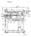
- FIG. 1 shows an example of a closed drift plasma motor 20 of electrons which includes a set of parts 22 of insulating material delimiting an annular channel 21 formed upstream of a first part constituted by a buffer chamber 23 and downstream of a second part constituted by a channel acceleration 24.
- the annular chamber 23 preferably has a dimension in the radial direction which is of the order of twice the dimension in the radial direction of the channel annular acceleration.
- An anode 25 connected by an electric line 43 to a voltage source DC 44, which can be for example of the order of 200 to 400 V, is arranged on the insulating pieces 22 delimiting the annular channel 21, in an area located immediately downstream of the buffer chamber 23, at the entrance to the acceleration channel 24.
- the supply line 43 of the anode 25 is disposed in an insulating tube 45 which crosses the bottom of the engine constituted by a plate 36 forming a cylinder head magnetic and parts 223, 224 of insulating material delimiting the chamber stamp 23.
- An ionizable gas supply tube 26 such as xenon passes through also the cylinder head 36 and the bottom 223 of the buffer chamber 23 for opening in an annular gas distributor 27 placed in the bottom of the buffer chamber 23.
- the channel 21 delimited by all of the insulating parts 22 is placed in a magnetic circuit composed essentially of three coils 31, 32, 33 and pole pieces 34, 35.
- Outer 34 and inner 35 pole pieces are placed in the engine exit plane outside the acceleration channel 24 and determine magnetic field lines which at the open part downstream of the acceleration channel 24, are substantially parallel to the outlet plane 59 of the motor 20.
- the magnetic circuit consisting of the pole pieces 34 and 35 is closed by an axial central core 38 and connecting bars 37 arranged at the periphery of the motor in an essentially cylindrical configuration, the central core 38 in ferromagnetic material and the connecting bars 37 made of ferromagnetic material being in contact with the rear cylinder head 36.
- the cylinder head 36 which is made of material ferromagnetic and constitutes the bottom of the motor, can be protected by one or several layers 30 of super thermal insulating material which eliminates the flow radiated to the satellite.
- Cathode 40 which is electrically connected by a line 42 to the negative pole of the voltage source 44, comprises a circuit 41 for supplying ionizable gas such as xenon, and located downstream of the exit zone of the acceleration channel 24.
- the hollow cathode 40 provides a plasma 29 substantially at the potential of reference from which are extracted the electrons going towards the anode 25 under the effect of electrostatic field E due to the difference between anode 25 and cathode 40.
- the field at the outlet of channel 24 is 12,000 to 16,000 Am -1 (150 to 200 Oe).
- the primary electrons are accelerated by the electrostatic field E, they then strike the wall of insulator 22, which provides secondary electrons lower energy.
- the xenon ions thus formed are accelerated by the electrostatic field E in acceleration channel 24.
- Neutralization of the ion beam is ensured by part of the electrons from the hollow cathode 40.
- the control of the radial magnetic field gradient obtained thanks to the arrangement of the coils 31 to 33 and of the pole pieces 34 and 35 makes it possible to separate the ion acceleration functions of the ionization function obtained in a area near the anode 25.
- the propellant gas flow rate (of Xenon) is determined by simple calibrated holes.
- the motor then has no active regulation.
- the discharge current is regulated by feedback on the Xenon flow using a heated valve or capillary.
- the object of the present invention is to make it possible to carry out in a simple and effective measurement of the thrust variations of a closed drift plasma motor of electrons.
- the invention also aims to allow easy determination of the value of the thrust of a plasma motor from the measurement of the thrust variations, and to effect active regulation of the thrust of a plasma motor from the measurement of engine thrust variations.
- a device for measuring and regulating variations of the thrust of a closed electron drift plasma engine comprising a main annular ionization and acceleration channel, at least one hollow cathode disposed outside the main channel downstream thereof, an anode, means supply of ionizable gas associated respectively with the hollow cathode and the anode, means for creating a magnetic field, and a plurality of flow sensors magnetic arranged around the acceleration channel.
- the device further comprises a plurality amplifiers whose inputs receive the respective signals delivered by the sensors magnetic flux, a summing circuit whose inputs are connected to the outputs of said amplifiers, and a plurality of weighting circuits interposed between the outputs of said amplifiers and the summing circuit, each weighting circuit performing weighting of the signal emitted by an amplifier using a determined coefficient by calibration, and the signals from the summing circuit are applied to a loop of feedback from a control circuit of a means control valve ionizable gas supply.
- the calibration device may include a turn capable of take several axial positions in the acceleration channel to determine the weighting coefficients of the weighting circuits.
- the device can further include an integrator circuit connected at the output of the summing circuit.
- the device comprises in in addition to a plurality of analog-to-digital converters arranged respectively at the output of the amplifiers, and a multiplexer whose inputs receive signals from analog-to-digital converters and whose output is connected to the input of the summing circuit to provide a digital output signal.
- the magnetic flux sensors are constituted by coils arranged around the acceleration channel.
- the device preferably comprises several coils serving as magnetic flux sensor arranged coaxially to the acceleration channel in various different radial planes of the acceleration channel.
- At least some of the flow sensors magnetic consist of coils supplied with direct current forming part said means for creating a magnetic field, and these magnetic flux sensors constituted by coils supplied with direct current are connected to the amplifiers respective via a filter eliminating the DC component.
- the feedback loop can be of numeric type and the value setpoint of the thrust is stored in a memory.
- the feedback loop can however also be of the type analog and the thrust setpoint is supplied from a mass flow meter associated with the means for supplying ionizable gas.
- Figure 2 schematically shows part of the example of closed electron drift plasma engine shown in Figure 1.
- the azimuthal current of electrons Jpe is not directly accessible to the measured.
- the device 100 for measuring thrust variations comprises flow sensors 101 to 104 arranged around the channel acceleration 24.
- the flow sensors 101 to 104 can be constituted by air coils coaxial with the acceleration channel 24. It can be used by example two pairs of coils 101, 104 and 102, 103 located one (101, 104) at the neighborhood of outlet section 225 of acceleration channel 24, the other (102, 103) near the anode 25 in the nearest part of the acceleration channel 24 of the buffer chamber 23. Other pairs of coils could also be arranged in intermediate sections with respect to the sections in which pairs 101, 104 and 102, 103 are located.
- Each pair of spools 101, 104 and 102, 103 includes a coil 101, 102 located in the peripheral part outer relative to the annular acceleration channel 24, and a coil 104, 103 located in the inner central part with respect to the acceleration channel 24.
- Figure 2 also shows the lines of induction magnetic Bp associated with the azimuthal current of electrons Jpe.
- the variations d ⁇ / dt of the magnetic flux ⁇ induced by the variations of the azimuthal current of electrons Jpe result in intensity variations in the coils 101 to 104.
- the coils 101 to 104 are connected to the inputs of amplifier circuits 111 to 114, the outputs of which are connected via weighting circuits 121 to 124 at the inputs of a summing circuit 115 (fig. 4)
- Each weighting circuit 121 to 124 performs a weighting of the signal emitted by an amplifier 111 to 114 using a coefficient determined by calibration.
- the calibration method can consist in using a coil 170 placed in a first position along the z axis of the acceleration channel 24, so concentric with the channel, to circulate in the coil 170 an Ipe calibration signal simulating the azimuthal current of electrons Jpe, to measure the output signals of n coils 101 to 104, then repeat the operation by placing the coil 170 in one other position along the z axis of the acceleration channel 24 The operation must be repeated k times for a number k of different positions along the z axis, k being greater or equal to the number n of coils 101 to 104. Dotted on the FIG. 7 the first position 171 and the k th position 172 of the coil 170.
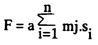
- This matrix makes it possible to establish the sensitivity coefficients to be assigned to the signal s i of each coil 101 to 104 in the weighting circuits 121 to 124, after amplification and before introduction of the signals into the summing circuit 115.
- the flow variation sensors such as coil 101
- the flow variation sensors are connected to amplifier-integrators 150.
- the integrated signal from the amplifier-integrator is proportional to the induced intensity, i.e. to the local variation of flow.
- the amplifier-integrator 150 can be produced in a simple manner. We have shown in Figure 5 an amplifier-integrator 150 built around the amplifier 111 associated with the coil 101. Resistors 151, 152 are connected between each input of amplifier 111 connected to one end of the coil 101 and ground. A capacitor 153 is connected between the output of amplifier 111 and one of the inputs. A reset push button 154 is mounted in parallel on the capacitor 153. In the case of mounting on satellite, the push button is of course replaced by a relay or a transistor controlled by on-board logic.
- the integration function intended to allow the reconstruction of a signal proportional to the thrust, and not to the variations in thrust, can also be provided downstream of the summing circuit 115, for example digitally, as will be described later with reference to FIG. 8.
- the coils 31 to 33 (see fig 1) providing the magnetic field can serve as a sensor when supplied with direct current from a constant current supply circuit 161 (fig 6).
- An adaptation circuit 160 must however be associated with the coil, such that the coil 31 to serve both as a means of creating a magnetic field in the acceleration channel 24 and the magnetic flux variation sensor.
- the adaptation circuit 160 essentially comprises a filter 163 comprising a connecting capacitor between one end of the coil 31 and an input of amplifier 111, in order to eliminate the DC component at the input of the amplifier 111.
- a resistor 162 is connected between the supply circuit constant current 161 and one end of the coil 31 in order to control the intensity of the direct current delivered to the coil 31.
- FIG. 3A shows an example of variations in the thrust F of a time-dependent plasma motor.
- Curve 201 in this case has a front upright 211, triangular irregularity 212 and sinusoidal irregularity 213 in the part of the curve 201 in the form of a plateau, and a falling edge 214.
- FIG. 3B shows the shape of the curve 205 corresponding to the intensity of the azimuthal current of electrons Jpe for the evolution of the thrust F represented on Figure 3A.
- zones 251 to 254 of the curve 205 which completely correspond to zones 211 to 214 of curve 201.
- FIG. 3C shows the shape of the curve 203 of the signals Si delivered by sensors 101 to 104 of magnetic flux variations in correspondence with the thrust variations F shown in FIG. 3A.
- the parties 231, 232, 233, 234 of the curve 203 correspond well to the derivative of the curve 201 of FIG. 3A and make it possible to detect the zones of variation 211 to 214 of the amplitude of the curve 201 corresponding to the thrust.
- Figure 3D shows the reconstruction of a curve 204 by integration of the signal illustrated by curve 203 of FIG. 3C.
- the reconstructed curve 204 corresponds well to the curve 201 in FIG. 3A relating to the thrust F.
- the signals delivered by the coils 101 to 104 of the detection device can be used in several different ways.
- the signals are used after integration in order to obtain a signal representing the thrust and possibly correct this thrust in a regulation loop, by action on the propellant gas flow injected into the engine.
- This type of application is particularly useful during engine start.
- the integrator circuit can be of analog type and combined with the circuits amplifiers 111 to 114, as decnt with reference to figure 5.
- the circuit integrator can also be placed at the output of summing circuit 115 and be distinct from amplifiers 111 to 114.
- An analog-type integrator is however likely to present a drift. That’s why it can be advantageous to implement a digital type integrator circuit, such as this will be described with reference to FIG. 8.
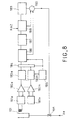
- Figure 8 shows an example of a digital control loop in which the coils such as the coil 101 are connected via low-pass filters 181a ... 181n at amplifier inputs 182a ... 182n including outputs are themselves connected to the inputs of analog-digital converters (CAN) 183a, ... 183n.
- Analog to digital converter outputs 183a ... 183n are connected to a multiplexer 184 clocked by a clock 185.
- the output of the multiplexer 184 is connected to a summing circuit 186 which provides a digital signal representative of the thrust variations to a comparator 190.
- a digital integrator circuit 188 is connected at the output of the summing circuit 187 to provide comparator 190 with an image of the thrust F.
- the integrator 188 which has a reset input, saves of integrated value.
- a circuit 189 also supplies comparator 190 with a thrust setpoint. The output of comparator 190 is used to control a valve regulation 191 placed on the propellant gas supply circuit ionizable.
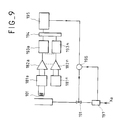
- FIG. 9 illustrates another example of application of the detection according to the invention.
- the signals delivered are used directly by the coils such as coils 101 to 104, after amplification and summation, but without performing integration.
Landscapes
- Engineering & Computer Science (AREA)
- Physics & Mathematics (AREA)
- Chemical & Material Sciences (AREA)
- Combustion & Propulsion (AREA)
- Plasma & Fusion (AREA)
- General Physics & Mathematics (AREA)
- Spectroscopy & Molecular Physics (AREA)
- Condensed Matter Physics & Semiconductors (AREA)
- Mechanical Engineering (AREA)
- General Engineering & Computer Science (AREA)
- Plasma Technology (AREA)
- Medicinal Preparation (AREA)
- Medicines That Contain Protein Lipid Enzymes And Other Medicines (AREA)
Description
- au sol, pendant les essais de recette, il faut mesurer la poussée par une balance, ce qui constitue une disposition assez contraignante ;
- en vol :
- lorsque deux moteurs sont en fonctionnement simultané, disposition répandue pour la correction Nord-Sud des satellites géostationnaires, un éventuel déséquilibre de poussée peut engendrer une perturbation d'attitude du satellite qu'il faut corriger par d'autres moteurs, alors qu'un dispositif de mesure et régulation de poussée permet d'annuler cette perturbation relative ;
- la méconnaissance de l'impulsion délivrée par correction oblige à effectuer un suivi de trajectoire régulier.
- la figure 1 est une vue en élévation et en demi-coupe axiale d'un exemple de moteur à plasma à dérive fermée d'électrons auquel est applicable le dispositif selon l'invention,
- la figure 2 est une vue schématique partielle en demi-coupe axiale du moteur à plasma de la figure 1, montrant une partie d'un dispositif de mesure de variations de poussée selon l'invention,
- les figures 3A à 3D sont des diagrammes montrant un exemple d'évolution de la poussée d'un moteur à plasma et de l'évolution correspondante d'autres grandeurs liées à la poussée,
- la figure 4 est une vue schématique des principaux éléments d'un dispositif de mesure de variations de poussée conforme à l'invention,
- la figure 5 est une vue partielle d'un mode particulier du dispositif de mesure de variations de poussée selon l'invention utilisant des amplificateurs-intégrateurs,
- la figure 6 est une vue partielle d'un mode particulier de dispositif de mesure de variations de poussée selon l'invention, dans lequel des bobines de création d'un champ magnétique faisant partie du moteur à plasma jouent également une fonction de capteurs dans le dispositif selon l'invention,
- la figure 7 est une vue schématique d'un dispositif selon l'invention auquel on a adjoint un élément de calibration pour réaliser une calibration des signaux fournis par les capteurs du dispositif,
- la figure 8 est un schéma montrant l'application du dispositif selon l'invention à une boucle de régulation numérique de la poussée d'un moteur à plasma, et
- la figure 9 est un schéma montrant l'application du dispositif selon l'invention à une boucle de régulation analogique de la poussée d'un moteur à plasma.

- au sol, pendant les essais de recette, une mesure électrique est plus simple qu'une mesure par balance de poussée ;
- il permet de simplifier le contrôle orbital d'un satellite géostationnaire : en effet, il est possible de délivrer une correction parfaitement calibrée en connaissant le temps de fonctionnement du moteur et la poussée, l'effet de cette dernière étant parfaitement prévisible, de sorte que les contrôles des paramètres orbitaux peuvent être ainsi espacés.
- il permet de contribuer à l'équilibre d'attitude d'un satellite en maintenant égales les poussées de deux moteurs tirant dans la même direction,
- un dispositif de mesure et régulation de poussée permet d'annuler un éventuel déséquilibre de poussée entre deux moteurs en tir simultané, cette perturbation relative de l'attitude du satellite est donc éliminée. Inversement, pour des besoins propres au satellite, par exemple pour une désaturation des roues de réaction, on peut volontairement créer une différence de poussée entre les deux moteurs induisant un couple connu.
- la possibilité de réguler directement la poussée permet d'effectuer un contrôle actif de la traínée pour des satellites en orbite basse.
Claims (9)
- Dispositif de mesure et de régulation de variations de la poussée d'un moteur à plasma à dérive fermée d'électrons comprenant un canal annulaire principal d'ionisation et d'accélération (24), au moins une cathode creuse (40) disposée à l'extérieur du canal principal en aval de celui-ci, une anode (25), des moyens (41,26) d'alimentation en gaz ionisable associés respectivement à la cathode creuse (40) et à l'anode (25), des moyens (31 à 33) de création d'un champ magnétique et une pluralité de capteurs de flux magnétique (101 à 104; 31 à 33) disposés autour du canal d'accélération (24), caractérisé en ce qu'il comprend en outre une pluralité d'amplificateurs (111 à 114) dont les entrées reçoivent les signaux respectifs délivrés par les capteurs de flux magnétique (101 à 104; 31 à 33), un circuit sommateur (115) dont les entrées sont reliées aux sorties desdits amplificateurs (111 à 114), et une pluralité de circuits de pondération (121 à 124) interposés entre les sorties desdits amplificateurs (111 à 114) et le circuit sommateur (115), chaque circuit de pondération (121 à 124) effectuant une pondération du signal émis par un amplificateur à l'aide d'un coefficient déterminé par calibration, et en ce que les signaux issus du circuit sommateur (115 ; 186 ; 195) sont appliqués à une boucle de contre-réaction (190 ; 196) d'un circuit de commande d'une vanne (191) de régulation des moyens (41, 26) d'alimentation en gaz ionisable.
- Dispositif selon la revendication 1, caractérisé en ce qu'il comprend en outre un circuit intégrateur (187) connecté en sortie du circuit sommateur (186) pour fournir une image directe de la poussée et réaliser un asservissement de poussée à l'aide d'une boucle de régulation (190,196) comprenant au moins une entrée recevant le signal du circuit sommateur (186), une entrée recevant le signal du circuit intégrateur (187), une entrée recevant une valeur de consigne de poussée et une sortie agissant sur ladite vanne de régulation (191).
- Dispositif selon l'une quelconque des revendications 1 et 2, caractérisé en ce qu'il comprend en outre une pluralité de convertisseurs analogique-numérique (183a, 183b) disposés respectivement, en sortie des amplificateurs (111 à 114 ; 182a, 182b), et un multiplexeur (184) dont les entrées reçoivent les signaux issus des convertisseurs analogique-numérique (183a, 183b) et dont la sortie est reliée à l'entrée du circuit sommateur (115 ; 186) pour fournir un signal de sortie de type numérique.
- Dispositif selon l'une quelconque des revendications 1 à 3, caractérisé en ce que sa calibration est assurée à l'aide d'une spire (170) susceptible de prendre plusieurs positions axiales (171, 172) dans le canal d'accélération (24) pour déterminer les coefficients de pondération des circuits de pondération (121 à 124).
- Dispositif selon l'une quelconque des revendications 1 à 4, caractérisé en ce que les capteurs de flux magnétique (101 à 104) sont constitués par des bobines disposées autour du canal d'accélération (24).
- Dispositif selon la revendication 5, caractérisé en ce qu'il comprend plusieurs bobines servant de capteur de flux magnétique (101, 104 ; 102, 103) disposées de façon coaxiale au canal d'accélération (24) dans divers plans radiaux différents du canal d'accélération (24).
- Dispositif selon la revendication 5, caractérisé en ce que certains au moins des capteurs de flux magnétique sont constitués par des bobines (31 à 33) alimentées en courant continu faisant partie desdits moyens de création d'un champ magnétique, et en ce que ces capteurs de flux magnétique constitués par des bobines (31 à 33) alimentées en courant continu sont reliés aux amplificateurs (111) respectifs par l'intermédiaire d'un filtre (163) éliminant la composante continue.
- Dispositif selon l'une quelconque des revendications 1 à 7, caractérisé en ce que la boucle de contre-réaction (190) est de type numérique et la valeur de consigne de la poussée est stockée dans une mémoire (189).
- Dispositif selon l'une quelconque des revendication 1 à 7, caractérisé en ce que la boucle de contre-réaction (196) est de type analogique et la valeur de consigne de la poussée est fournie à partir d'un débitmètre massique (197) associé aux moyens (41, 26) d'alimentation en gaz ionisable.
Applications Claiming Priority (1)
| Application Number | Priority Date | Filing Date | Title |
|---|---|---|---|
| PCT/FR1993/000609 WO1995001085A1 (fr) | 1993-06-21 | 1993-06-21 | Dispositif de mesure de variations de la poussee d'un moteur a plasma a derive fermee d'electrons |
Publications (2)
| Publication Number | Publication Date |
|---|---|
| EP0656170A1 EP0656170A1 (fr) | 1995-06-07 |
| EP0656170B1 true EP0656170B1 (fr) | 1998-04-22 |
Family
ID=9443265
Family Applications (1)
| Application Number | Title | Priority Date | Filing Date |
|---|---|---|---|
| EP93913163A Expired - Lifetime EP0656170B1 (fr) | 1993-06-21 | 1993-06-21 | Dispositif de mesure de variations de la poussee d'un moteur a plasma a derive fermee d'electrons |
Country Status (8)
| Country | Link |
|---|---|
| US (1) | US5509266A (fr) |
| EP (1) | EP0656170B1 (fr) |
| JP (1) | JPH08500935A (fr) |
| CA (1) | CA2141605A1 (fr) |
| DE (1) | DE69318162T2 (fr) |
| RU (1) | RU2107186C1 (fr) |
| UA (1) | UA41889C2 (fr) |
| WO (1) | WO1995001085A1 (fr) |
Families Citing this family (17)
| Publication number | Priority date | Publication date | Assignee | Title |
|---|---|---|---|---|
| RU2084085C1 (ru) * | 1995-07-14 | 1997-07-10 | Центральный научно-исследовательский институт машиностроения | Ускоритель с замкнутым дрейфом электронов |
| US6075321A (en) * | 1998-06-30 | 2000-06-13 | Busek, Co., Inc. | Hall field plasma accelerator with an inner and outer anode |
| FR2782884B1 (fr) * | 1998-08-25 | 2000-11-24 | Snecma | Propulseur a plasma a derive fermee d'electrons adapte a de fortes charges thermiques |
| DE10014034C2 (de) * | 2000-03-22 | 2002-01-24 | Thomson Tubes Electroniques Gm | Plasma-Beschleuniger-Anordnung |
| RU2234619C2 (ru) * | 2002-04-25 | 2004-08-20 | Федеральное государственное унитарное предприятие Российского авиационно-космического агентства "Опытное конструкторское бюро "Факел" | Способ изготовления плазменного двигателя |
| US6696792B1 (en) | 2002-08-08 | 2004-02-24 | The United States Of America As Represented By The United States National Aeronautics And Space Administration | Compact plasma accelerator |
| KR100493164B1 (ko) * | 2002-12-14 | 2005-06-02 | 삼성전자주식회사 | 전자기 유도 가속기 |
| RU2251090C1 (ru) * | 2003-09-01 | 2005-04-27 | Федеральное государственное унитарное предприятие "Опытное конструкторское бюро "Факел" | Способ прогнозирования изменения параметров стационарного плазменного двигателя в процессе выработки ресурса |
| US7530218B2 (en) * | 2004-07-14 | 2009-05-12 | The Johns Hopkins University | Pulsed plasma thruster using vapor |
| US20060026886A1 (en) * | 2004-07-15 | 2006-02-09 | Doukas Antonios E | Rapid activation system for a laser-sighting assembly |
| JP4650136B2 (ja) * | 2005-07-19 | 2011-03-16 | 三菱電機株式会社 | ホールスラスタシミュレータ |
| RU2312316C1 (ru) * | 2006-02-20 | 2007-12-10 | Федеральное государственное унитарное предприятие "Научно-производственное объединение прикладной механики им. академика М.Ф. Решетнева" | Способ измерения тяги электрореактивных двигателей и устройство для его реализации |
| RU2351800C1 (ru) * | 2007-08-02 | 2009-04-10 | Открытое акционерное общество "Ракетно-космическая корпорация "Энергия" имени С.П. Королева" | Магнитоплазмодинамический двигатель и способ его работы |
| FR3039861B1 (fr) * | 2015-08-07 | 2017-09-01 | Snecma | Systeme de propulsion electrique a propulseurs a plasma stationnaire avec unique unite d'alimentation electrique |
| RU2743606C1 (ru) * | 2020-09-28 | 2021-02-20 | федеральное государственное бюджетное образовательное учреждение высшего образования "Московский государственный технический университет имени Н.Э. Баумана (национальный исследовательский университет)" (МГТУ им. Н.Э. Баумана) | Способ ускоренного определения ресурса элементов двигателя с замкнутым дрейфом электронов |
| CN117907907B (zh) * | 2024-01-22 | 2024-08-16 | 哈尔滨工业大学 | 用于监测空心阴极节流孔内自伴磁场的磁探针 |
| CN118067399B (zh) * | 2024-04-19 | 2024-06-25 | 哈尔滨工业大学 | 等离子体推进器在轨状态的近场羽流成像监测方法 |
Family Cites Families (3)
| Publication number | Priority date | Publication date | Assignee | Title |
|---|---|---|---|---|
| US4821508A (en) * | 1985-06-10 | 1989-04-18 | Gt-Devices | Pulsed electrothermal thruster |
| US5051659A (en) * | 1991-01-30 | 1991-09-24 | The United States Of America As Represented By The Secretary Of The Navy | Bulk plasma generation |
| IT1246684B (it) * | 1991-03-07 | 1994-11-24 | Proel Tecnologie Spa | Propulsore ionico a risonanza ciclotronica. |
-
1993
- 1993-06-21 RU RU95106611A patent/RU2107186C1/ru not_active IP Right Cessation
- 1993-06-21 UA UA94129230A patent/UA41889C2/uk unknown
- 1993-06-21 DE DE69318162T patent/DE69318162T2/de not_active Expired - Fee Related
- 1993-06-21 WO PCT/FR1993/000609 patent/WO1995001085A1/fr not_active Ceased
- 1993-06-21 CA CA002141605A patent/CA2141605A1/fr not_active Abandoned
- 1993-06-21 EP EP93913163A patent/EP0656170B1/fr not_active Expired - Lifetime
- 1993-06-21 JP JP7502489A patent/JPH08500935A/ja active Pending
- 1993-06-21 US US08/381,866 patent/US5509266A/en not_active Expired - Fee Related
Also Published As
| Publication number | Publication date |
|---|---|
| WO1995001085A1 (fr) | 1995-01-05 |
| US5509266A (en) | 1996-04-23 |
| UA41889C2 (uk) | 2001-10-15 |
| CA2141605A1 (fr) | 1995-01-05 |
| RU2107186C1 (ru) | 1998-03-20 |
| RU95106611A (ru) | 1996-11-20 |
| JPH08500935A (ja) | 1996-01-30 |
| EP0656170A1 (fr) | 1995-06-07 |
| DE69318162T2 (de) | 1998-12-03 |
| DE69318162D1 (de) | 1998-05-28 |
Similar Documents
| Publication | Publication Date | Title |
|---|---|---|
| EP0656170A1 (fr) | Dispositif de mesure de variations de la poussee d'un moteur a plasma a derive fermee d'electrons | |
| EP3146205B1 (fr) | Moteur pour engin spatial, et engin spatial comprenant un tel moteur | |
| CA2695238C (fr) | Dispositif d'ejection d'ions a effet hall | |
| FR3038663B1 (fr) | Propulseur a effet hall exploitable en haute altitude | |
| CA2996431C (fr) | Propulseur ionique a grille avec agent propulsif solide integre | |
| EP1496727B1 (fr) | Accélérateur à plasma à dérive fermée d'électrons | |
| FR2986577A1 (fr) | Propulseur a effet hall | |
| FR2906961A1 (fr) | Appareil d'alimentation pour controler un accelerateur d'ions | |
| WO1995000758A1 (fr) | Moteur a plasma de longueur reduite a derive fermee d'electrons | |
| FR2786359A1 (fr) | Tube a neutrons hermetique | |
| WO2013076409A1 (fr) | Propulseur a effet de hall | |
| EP0006669A1 (fr) | Machine électrique à reluctance variable | |
| FR3071886B1 (fr) | Propulseur a effet hall bi-etage | |
| Lee et al. | Distinct discharge modes in micro Hall thruster plasmas | |
| Touzeau et al. | Plasma diagnostic systems for Hall-effect plasma thrusters | |
| Spethmann et al. | Force probes for development and testing of different electric propulsion systems | |
| WO2004007957A2 (fr) | Propulseur plasmique a effet hall | |
| EP3250822B1 (fr) | Propulseur à effet hall et engin spatial comprenant un tel propulseur | |
| Leiter et al. | RIT-ÁX-The New Modular High Precision Micro Ion Propulsion System | |
| EP0483004B1 (fr) | Source d'ions fortement chargés à sonde polarisable et à résonance cyclotronique électronique | |
| FR2728229A1 (fr) | Bouclier de freinage pour engin spatial et satellite ainsi equipe | |
| Guyot et al. | Electrostatic propulsion for satellites application to the Robusta-3 nanosatellite | |
| Ferreira et al. | Permanent magnet Hall Thrusters development and applications on future brazilian space missions | |
| EP0813223B1 (fr) | Dispositif pour engendrer un champ magnétique et source ecr comportant ce dispositif | |
| Torkar et al. | Effects of active spacecraft potential control on cluster plasma measurements-first results |
Legal Events
| Date | Code | Title | Description |
|---|---|---|---|
| PUAI | Public reference made under article 153(3) epc to a published international application that has entered the european phase |
Free format text: ORIGINAL CODE: 0009012 |
|
| 17P | Request for examination filed |
Effective date: 19950214 |
|
| AK | Designated contracting states |
Kind code of ref document: A1 Designated state(s): CH DE ES FR GB IT LI NL SE |
|
| 17Q | First examination report despatched |
Effective date: 19951106 |
|
| RAP1 | Party data changed (applicant data changed or rights of an application transferred) |
Owner name: SOCIETE EUROPEENNE DE PROPULSION |
|
| GRAG | Despatch of communication of intention to grant |
Free format text: ORIGINAL CODE: EPIDOS AGRA |
|
| GRAG | Despatch of communication of intention to grant |
Free format text: ORIGINAL CODE: EPIDOS AGRA |
|
| GRAH | Despatch of communication of intention to grant a patent |
Free format text: ORIGINAL CODE: EPIDOS IGRA |
|
| GRAH | Despatch of communication of intention to grant a patent |
Free format text: ORIGINAL CODE: EPIDOS IGRA |
|
| GRAA | (expected) grant |
Free format text: ORIGINAL CODE: 0009210 |
|
| RAP1 | Party data changed (applicant data changed or rights of an application transferred) |
Owner name: SOCIETE NATIONALE D'ETUDE ET DE CONSTRUCTION DE MO |
|
| AK | Designated contracting states |
Kind code of ref document: B1 Designated state(s): CH DE ES FR GB IT LI NL SE |
|
| PG25 | Lapsed in a contracting state [announced via postgrant information from national office to epo] |
Ref country code: NL Free format text: LAPSE BECAUSE OF FAILURE TO SUBMIT A TRANSLATION OF THE DESCRIPTION OR TO PAY THE FEE WITHIN THE PRESCRIBED TIME-LIMIT Effective date: 19980422 Ref country code: ES Free format text: THE PATENT HAS BEEN ANNULLED BY A DECISION OF A NATIONAL AUTHORITY Effective date: 19980422 |
|
| REG | Reference to a national code |
Ref country code: CH Ref legal event code: EP |
|
| REF | Corresponds to: |
Ref document number: 69318162 Country of ref document: DE Date of ref document: 19980528 |
|
| PGFP | Annual fee paid to national office [announced via postgrant information from national office to epo] |
Ref country code: GB Payment date: 19980616 Year of fee payment: 6 |
|
| PGFP | Annual fee paid to national office [announced via postgrant information from national office to epo] |
Ref country code: DE Payment date: 19980617 Year of fee payment: 6 |
|
| ITF | It: translation for a ep patent filed | ||
| PG25 | Lapsed in a contracting state [announced via postgrant information from national office to epo] |
Ref country code: LI Free format text: LAPSE BECAUSE OF NON-PAYMENT OF DUE FEES Effective date: 19980630 Ref country code: CH Free format text: LAPSE BECAUSE OF NON-PAYMENT OF DUE FEES Effective date: 19980630 |
|
| PG25 | Lapsed in a contracting state [announced via postgrant information from national office to epo] |
Ref country code: SE Free format text: LAPSE BECAUSE OF FAILURE TO SUBMIT A TRANSLATION OF THE DESCRIPTION OR TO PAY THE FEE WITHIN THE PRESCRIBED TIME-LIMIT Effective date: 19980722 |
|
| GBT | Gb: translation of ep patent filed (gb section 77(6)(a)/1977) |
Effective date: 19980715 |
|
| NLV1 | Nl: lapsed or annulled due to failure to fulfill the requirements of art. 29p and 29m of the patents act | ||
| REG | Reference to a national code |
Ref country code: CH Ref legal event code: PL |
|
| PLBE | No opposition filed within time limit |
Free format text: ORIGINAL CODE: 0009261 |
|
| STAA | Information on the status of an ep patent application or granted ep patent |
Free format text: STATUS: NO OPPOSITION FILED WITHIN TIME LIMIT |
|
| 26N | No opposition filed | ||
| PG25 | Lapsed in a contracting state [announced via postgrant information from national office to epo] |
Ref country code: GB Free format text: LAPSE BECAUSE OF NON-PAYMENT OF DUE FEES Effective date: 19990621 |
|
| GBPC | Gb: european patent ceased through non-payment of renewal fee |
Effective date: 19990621 |
|
| PG25 | Lapsed in a contracting state [announced via postgrant information from national office to epo] |
Ref country code: DE Free format text: LAPSE BECAUSE OF NON-PAYMENT OF DUE FEES Effective date: 20000503 |
|
| REG | Reference to a national code |
Ref country code: FR Ref legal event code: TP Ref country code: FR Ref legal event code: CD |
|
| PG25 | Lapsed in a contracting state [announced via postgrant information from national office to epo] |
Ref country code: IT Free format text: LAPSE BECAUSE OF NON-PAYMENT OF DUE FEES Effective date: 20050621 |
|
| REG | Reference to a national code |
Ref country code: FR Ref legal event code: TP Owner name: SNECMA, FR Effective date: 20120323 Ref country code: FR Ref legal event code: CD Owner name: SNECMA, FR Effective date: 20120323 |
|
| PGFP | Annual fee paid to national office [announced via postgrant information from national office to epo] |
Ref country code: FR Payment date: 20120621 Year of fee payment: 20 |