EP0655822B1 - A miniature electric motor - Google Patents
A miniature electric motor Download PDFInfo
- Publication number
- EP0655822B1 EP0655822B1 EP19940308344 EP94308344A EP0655822B1 EP 0655822 B1 EP0655822 B1 EP 0655822B1 EP 19940308344 EP19940308344 EP 19940308344 EP 94308344 A EP94308344 A EP 94308344A EP 0655822 B1 EP0655822 B1 EP 0655822B1
- Authority
- EP
- European Patent Office
- Prior art keywords
- cover
- motor
- end cap
- terminals
- casing
- Prior art date
- Legal status (The legal status is an assumption and is not a legal conclusion. Google has not performed a legal analysis and makes no representation as to the accuracy of the status listed.)
- Expired - Lifetime
Links
Images

Classifications
-
- H—ELECTRICITY
- H02—GENERATION; CONVERSION OR DISTRIBUTION OF ELECTRIC POWER
- H02K—DYNAMO-ELECTRIC MACHINES
- H02K5/00—Casings; Enclosures; Supports
- H02K5/04—Casings or enclosures characterised by the shape, form or construction thereof
- H02K5/10—Casings or enclosures characterised by the shape, form or construction thereof with arrangements for protection from ingress, e.g. water or fingers
-
- H—ELECTRICITY
- H01—ELECTRIC ELEMENTS
- H01R—ELECTRICALLY-CONDUCTIVE CONNECTIONS; STRUCTURAL ASSOCIATIONS OF A PLURALITY OF MUTUALLY-INSULATED ELECTRICAL CONNECTING ELEMENTS; COUPLING DEVICES; CURRENT COLLECTORS
- H01R13/00—Details of coupling devices of the kinds covered by groups H01R12/70 or H01R24/00 - H01R33/00
- H01R13/02—Contact members
- H01R13/20—Pins, blades, or sockets shaped, or provided with separate member, to retain co-operating parts together
-
- H—ELECTRICITY
- H02—GENERATION; CONVERSION OR DISTRIBUTION OF ELECTRIC POWER
- H02K—DYNAMO-ELECTRIC MACHINES
- H02K5/00—Casings; Enclosures; Supports
- H02K5/04—Casings or enclosures characterised by the shape, form or construction thereof
- H02K5/22—Auxiliary parts of casings not covered by groups H02K5/06-H02K5/20, e.g. shaped to form connection boxes or terminal boxes
- H02K5/225—Terminal boxes or connection arrangements
Definitions
- the present invention relates to a miniature electric motor and in particular to a miniature motor with a splashproof cover.
- Small permanent magnet d.c. motors may be used in situations where they may be exposed to water, for example, in vehicles.
- a splashproof or waterproof sleeve can be put over the can-like motor casing.
- Different vehicle manufacturers require different terminal configurations which obliges the motor manufacturer to provide end caps with different configurations.
- the cover was designed specifically for the end cap of an electric motor having male motor terminals and also required the end cap to be manufactured with separate slots formed in the end cap to receive mounting or locking pins. Accordingly, the splashproof cover had apertures in the body of the cover adapted to receive the male motor terminals and electrically connect them with the external terminals of the splashproof cover.
- the present invention aims to at least reduce the disadvantages of known splashproof covers for miniature motors and in particular, to provide a splashproof cover for a miniature motor having female terminals.
- This arrangement reduces the likelihood of damage to the motor terminals due to misalignment during fitting of the cover to the end cap because, firstly, the male terminals on the cover can be made larger or thicker than the standard male motor terminal but more importantly, because the female motor terminals are located within the end cap of the motor, a greater lead-in portion to the female terminals can be provided to guide the cover terminals into position without damage.
- An additional advantage is that a standard end cap assembly with female-type motor terminals can be used with the user's specified terminal arrangements being provided by the cover which is a simple insert moulded part. Hence no changes need to be made to the end cap assembly design or manufacturing process which is important with automated assembly lines where even small changes result in expensive and time consuming re-configuration and adjustments to the automated assembly machines.
- the present invention provides a miniature electric motor comprising a can-like casing having one open end, an end cap closing the open end of the casing and supporting motor terminals, a rotor including a shaft rotatably mounted in bearings fitted to the end cap and casing, and a splashproof cover covering the end cap and connecting the motor terminals to an external connector formed on the cover, wherein the motor terminals are female terminals disposed in slots formed in the end cap and the cover has tongue-like terminals with serrated edges disposed within the slots and making electrical contact with the female terminals, the serrated edges of the cover terminals being engaged with end walls of the slots to resist removal from the slots, thereby securing the cover to the end cap.
- the tongues are formed integrally with respect to the conductors from a sheet of conductive material.
- the tongues are formed as part of the conductors and thus eliminating the need for an additional connection between the tongues and the connectors.
- the cover has a locating pin which mates with a corresponding hole in the end cap to ensure that the cover can only be fitted to the end cap in one orientation to avoid reversing the motor connections.
- the cover preferably has an integrally formed peripheral skirt arranged to encircle an outer periphery of the end cap.
- the skirt may be adapted to form a water resistant or waterproof seal with a housing of an appliance to which the motor is fitted.
- Figures 1 and 5 show a miniature p.m.d.c. motor 1 having a housing comprising a deep drawn can-like steel casing 2 and a plastics end cap 3.
- a shaft 4 is journalled in bearings in the casing 2 and end cap 3.
- the shaft 4 carries a wound armature and commutator (not shown) and the casing 2 carries two permanent magnets (also not shown).
- the end cap 3 carries brush gear (not shown) electrically connected to two motor terminals 5 for supplying power to the commutator.
- the construction thus far described is well known in the art.
- the two motor terminals 5 are female terminals located within respective slots 6 formed in the end cap.
- the slots have side walls facing the motor terminals and end walls joining the side walls and facing the edges of the motor terminals.
- a splashproof cover 7 according to the preferred embodiment of the present invention is shown in Figure 1 fitted to the motor 1.
- the cover 7, as more clearly shown in Figures 2, 3 and 4, comprises a moulded plastics material body 8 having a peripheral skirt 9 which encircles the outer periphery 10 of the end cap 3.
- An inner surface 11 of the body 8 bears against the outer surface 12 of the end cap 3 and has a recess 13 for receiving a boss 14 on the end cap which carries a shaft bearing (not shown).
- a socket 15 housing two connector terminals 16 is integrally formed on the body 8.
- the conductors 17 are insert moulded in the cover 7.
- the conductors each comprise a planar body part 18 encased by the body 8.
- the connector terminals 16 are integral with the conductors and extend out of the plane of the respective body parts 18 into the socket 15 for connecting to an external power supply.
- Each conductor 17 further comprises a tongue 19 formed integrally with the body part and extending transversely to the plane of the body part to mate with a respective female terminal 5 of the motor to make electrical contact therewith.
- the tongues thus form male terminals on the cover.
- the tongues or cover terminals 19 have sawtooth or serrated edges 20 that are arranged to grip the end walls of the female terminal slot 6 in the end cap 3 to resist removal of the tongue from the slot, thus locking the cover to the end cap.
- a post 22 extends perpendicularly from the inner surface 11 of the body 8 to mate with a corresponding hole in the end cap (not shown) in order to assist alignment of the tongues with the female terminal slots 6 and to prevent the cover from being fitted around the wrong way.
- the motor end cap 3 is of standard configuration and may have vent holes or hollow rivets therein through which water can enter the motor.
- the motor is usable without the cover 7, electrical connection being made to the motor terminals 5 in the usual way.
- the cover 7 is slid over the end cap 3.
- the tongues 19 penetrating the slot 6 and mating with the female terminals 5 of the motor.
- the sawtooth or serrated edges 20 of the tongues grip the end walls of the slot 6 to hold the cover on the end cap.
- the post 22 ensures that the cover will fit on the end cap in only one orientation to avoid reversing the polarity of the motor.
- the inner surface 11 bears against the end cap to cover any vent holes or other apertures in the end cap.
- a power supply may then be connected to the connector 15 to supply power to the motor brush gear via connector terminals 16, body parts 18, tongues 19 and motor terminals 5.
- the skirt 9 may be a snug fit about the periphery 10 of the end cap to inhibit the ingress of water between the cover and the end cap. Also, the skirt may extend down the side of the motor, over the casing 2. A sleeve (not shown) may enclose the casing 2 and mate with the skirt 9 to cover any vent holes, etc., in the casing.
- the cover 7 is shown with an extended peripheral skirt 9 which has a smaller outer skirt or lip 9A forming an annular axially extending recess 29.
- This recess is adapted or arranged to mate with a housing part 30 of an appliance to which the motor is fitted to produce a water resistant or waterproof seal between the cover and the housing to seal the housing and/or protect the motor.
- the connector 15 may be of various shapes to suit the customers' connection requirements whilst the shape of the end cap can remain constant.
- a standard motor can be adapted to suit various customers' connection requirements by using a splashproof cover with varying connector configurations. This is cost effective as the cost of producing a variety of covers is less than producing a variety of end caps.
- a motor with female terminals separate cover terminals and mounting tongues can be avoided while allowing greater tolerance in the alignment between the end cap and the cover during fitting.
Description
- The present invention relates to a miniature electric motor and in particular to a miniature motor with a splashproof cover.
- Small permanent magnet d.c. motors may be used in situations where they may be exposed to water, for example, in vehicles. To prolong efficient motor operation, a splashproof or waterproof sleeve can be put over the can-like motor casing. However, it is not easy to cover the motor end cap due to the presence of the terminals. Different vehicle manufacturers require different terminal configurations which obliges the motor manufacturer to provide end caps with different configurations.
- A prior design proposed by the present applicant is described in GB2225672. The cover was designed specifically for the end cap of an electric motor having male motor terminals and also required the end cap to be manufactured with separate slots formed in the end cap to receive mounting or locking pins. Accordingly, the splashproof cover had apertures in the body of the cover adapted to receive the male motor terminals and electrically connect them with the external terminals of the splashproof cover.
- While this cover performed satisfactorily, it did have a disadvantage in that a significant number of motor terminals were damaged during assembly of the splashproof cover to the motor end cap resulting in unsatisfactory connections between the motor terminal and the terminals of the cover. This was caused by a slight misalignment between the motor terminals and the apertures in the cover during assembly. Due to the thinness of the cover in the area of the apertures, there was not sufficient material to provide an adequate lead-in to the apertures for the motor terminals to accommodate the misalignment during assembly. Making the cover thicker to provide this lead-in increased the length of the motor.
- The present invention aims to at least reduce the disadvantages of known splashproof covers for miniature motors and in particular, to provide a splashproof cover for a miniature motor having female terminals. This is achieved by providing the splashproof cover with axially extending male terminals adapted to engage the female motor terminals located within slots formed in the end cap and the cover terminals having serrated or sawtooth like edges which bite into the end walls of the slots to secure the cover to the end cap. This does away with the apertures on the splashproof cover and the need for separate mounting or holding pins to secure the cover to the end cap.
- This arrangement reduces the likelihood of damage to the motor terminals due to misalignment during fitting of the cover to the end cap because, firstly, the male terminals on the cover can be made larger or thicker than the standard male motor terminal but more importantly, because the female motor terminals are located within the end cap of the motor, a greater lead-in portion to the female terminals can be provided to guide the cover terminals into position without damage.
- An additional advantage is that a standard end cap assembly with female-type motor terminals can be used with the user's specified terminal arrangements being provided by the cover which is a simple insert moulded part. Hence no changes need to be made to the end cap assembly design or manufacturing process which is important with automated assembly lines where even small changes result in expensive and time consuming re-configuration and adjustments to the automated assembly machines.
- Thus, in one aspect, the present invention provides a miniature electric motor comprising a can-like casing having one open end, an end cap closing the open end of the casing and supporting motor terminals, a rotor including a shaft rotatably mounted in bearings fitted to the end cap and casing, and a splashproof cover covering the end cap and connecting the motor terminals to an external connector formed on the cover, wherein the motor terminals are female terminals disposed in slots formed in the end cap and the cover has tongue-like terminals with serrated edges disposed within the slots and making electrical contact with the female terminals, the serrated edges of the cover terminals being engaged with end walls of the slots to resist removal from the slots, thereby securing the cover to the end cap.
- Preferably, the tongues are formed integrally with respect to the conductors from a sheet of conductive material. In this manner, the tongues are formed as part of the conductors and thus eliminating the need for an additional connection between the tongues and the connectors.
- It is also preferable that the cover has a locating pin which mates with a corresponding hole in the end cap to ensure that the cover can only be fitted to the end cap in one orientation to avoid reversing the motor connections.
- The cover preferably has an integrally formed peripheral skirt arranged to encircle an outer periphery of the end cap. The skirt may be adapted to form a water resistant or waterproof seal with a housing of an appliance to which the motor is fitted.
- Preferred embodiments of the invention will now be described, by way of example only, with reference to the accompanying drawings, in which:
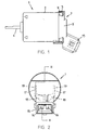
- Figure 1 is a side view of a miniature p.m.d.c. motor having fitted thereon a splashproof cover according to the present invention, shown in partial section;
- Figure 2 illustrates an end view of the outside of the cover of Figure 1;
- Figure 3 is a cross section along Line III-III of Figure 2;
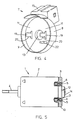
- Figure 4 is a perspective view of the end cap of Figure 1 showing the inside surface;
- Figure 5 is a partly cutaway plane view of the motor of Figure 1; and
- Figure 6 is a similar view to Figure 3 of another embodiment.
- Referring to the drawings, Figures 1 and 5 show a miniature p.m.d.c.
motor 1 having a housing comprising a deep drawn can-like steel casing 2 and aplastics end cap 3. Ashaft 4 is journalled in bearings in thecasing 2 and endcap 3. Theshaft 4 carries a wound armature and commutator (not shown) and thecasing 2 carries two permanent magnets (also not shown). Theend cap 3 carries brush gear (not shown) electrically connected to twomotor terminals 5 for supplying power to the commutator. The construction thus far described is well known in the art. - The two
motor terminals 5 are female terminals located within respective slots 6 formed in the end cap. The slots have side walls facing the motor terminals and end walls joining the side walls and facing the edges of the motor terminals. - A
splashproof cover 7 according to the preferred embodiment of the present invention is shown in Figure 1 fitted to themotor 1. Thecover 7, as more clearly shown in Figures 2, 3 and 4, comprises a mouldedplastics material body 8 having aperipheral skirt 9 which encircles theouter periphery 10 of theend cap 3. Aninner surface 11 of thebody 8 bears against theouter surface 12 of theend cap 3 and has arecess 13 for receiving aboss 14 on the end cap which carries a shaft bearing (not shown). Asocket 15 housing twoconnector terminals 16 is integrally formed on thebody 8. - Two
conductors 17 are insert moulded in thecover 7. The conductors each comprise aplanar body part 18 encased by thebody 8. Theconnector terminals 16 are integral with the conductors and extend out of the plane of therespective body parts 18 into thesocket 15 for connecting to an external power supply. Eachconductor 17 further comprises atongue 19 formed integrally with the body part and extending transversely to the plane of the body part to mate with a respectivefemale terminal 5 of the motor to make electrical contact therewith. The tongues thus form male terminals on the cover. The tongues orcover terminals 19 have sawtooth orserrated edges 20 that are arranged to grip the end walls of the female terminal slot 6 in theend cap 3 to resist removal of the tongue from the slot, thus locking the cover to the end cap. - A
post 22 extends perpendicularly from theinner surface 11 of thebody 8 to mate with a corresponding hole in the end cap (not shown) in order to assist alignment of the tongues with the female terminal slots 6 and to prevent the cover from being fitted around the wrong way. - The
motor end cap 3 is of standard configuration and may have vent holes or hollow rivets therein through which water can enter the motor. The motor is usable without thecover 7, electrical connection being made to themotor terminals 5 in the usual way. In use, thecover 7 is slid over theend cap 3. Thetongues 19 penetrating the slot 6 and mating with thefemale terminals 5 of the motor. The sawtooth orserrated edges 20 of the tongues grip the end walls of the slot 6 to hold the cover on the end cap. Thepost 22 ensures that the cover will fit on the end cap in only one orientation to avoid reversing the polarity of the motor. Theinner surface 11 bears against the end cap to cover any vent holes or other apertures in the end cap. A power supply may then be connected to theconnector 15 to supply power to the motor brush gear viaconnector terminals 16,body parts 18,tongues 19 andmotor terminals 5. - The
skirt 9 may be a snug fit about theperiphery 10 of the end cap to inhibit the ingress of water between the cover and the end cap. Also, the skirt may extend down the side of the motor, over thecasing 2. A sleeve (not shown) may enclose thecasing 2 and mate with theskirt 9 to cover any vent holes, etc., in the casing. - In Figure 6, the
cover 7 is shown with an extendedperipheral skirt 9 which has a smaller outer skirt orlip 9A forming an annular axially extendingrecess 29. This recess is adapted or arranged to mate with ahousing part 30 of an appliance to which the motor is fitted to produce a water resistant or waterproof seal between the cover and the housing to seal the housing and/or protect the motor. - The
connector 15 may be of various shapes to suit the customers' connection requirements whilst the shape of the end cap can remain constant. Thus, a standard motor can be adapted to suit various customers' connection requirements by using a splashproof cover with varying connector configurations. This is cost effective as the cost of producing a variety of covers is less than producing a variety of end caps. By using a motor with female terminals, separate cover terminals and mounting tongues can be avoided while allowing greater tolerance in the alignment between the end cap and the cover during fitting.
Claims (5)
- A miniature electric motor comprising a can-like casing (2) having one open end, an end cap (3) closing the open end of the casing and supporting motor terminals (5), a rotor including a shaft (4) rotatably mounted in bearings fitted to the end cap (3) and casing (2), and a splashproof cover (7) covering the end cap (3) and connecting the motor terminals (5) to an external connector (15) formed on the cover (3), characterized in that the motor terminals (5) are female terminals disposed in slots (6) formed in the end cap (3) and the cover (7) has tongue-like terminals (19) with serrated edges (20) disposed within the slots (6) and making electrical contact with the female terminals (5), the serrated edges (20) of the cover terminals (19) being engaged with end walls of the slots (6) to resist removal from the slots, thereby securing the cover (7) to the end cap (3).
- A motor as defined in Claim 1 wherein the cover has a dependent peripheral skirt (9) which extends axially of the motor along an outer periphery of the end cap.
- A motor as defined in Claim 2 wherein the peripheral skirt (9) extends axially of the motor to cover at least a portion of the casing (2) and is adapted to sealingly engage with a housing of an appliance to which the motor is fitted.
- A motor as defined in any one of the preceding claims wherein the cover (7) comprises a generally circular solid moulded plastics material planar body (8) integrally formed with the external connector (15) and embedding conductors (17) integral with the tongue-like terminals (19) and forming terminal elements (16) in the external connector.
- A motor as defined in any one of the preceding claims wherein means (22) formed between the cover (7) and the end cap (3) allows fitting of the cover (7) to the end cap (3) in only one orientation.
Applications Claiming Priority (2)
| Application Number | Priority Date | Filing Date | Title |
|---|---|---|---|
| GB939323932A GB9323932D0 (en) | 1993-11-20 | 1993-11-20 | Splashproof cover for a miniature electric motor |
| GB9323932 | 1993-11-20 |
Publications (2)
| Publication Number | Publication Date |
|---|---|
| EP0655822A1 EP0655822A1 (en) | 1995-05-31 |
| EP0655822B1 true EP0655822B1 (en) | 1997-09-03 |
Family
ID=10745466
Family Applications (1)
| Application Number | Title | Priority Date | Filing Date |
|---|---|---|---|
| EP19940308344 Expired - Lifetime EP0655822B1 (en) | 1993-11-20 | 1994-11-11 | A miniature electric motor |
Country Status (6)
| Country | Link |
|---|---|
| EP (1) | EP0655822B1 (en) |
| JP (1) | JP3605425B2 (en) |
| CN (1) | CN1038087C (en) |
| DE (1) | DE69405355T2 (en) |
| ES (1) | ES2108388T3 (en) |
| GB (1) | GB9323932D0 (en) |
Families Citing this family (21)
| Publication number | Priority date | Publication date | Assignee | Title |
|---|---|---|---|---|
| TW351027B (en) * | 1996-04-22 | 1999-01-21 | Seiko Epson Corp | Small motor and the motor drive |
| DE29702510U1 (en) * | 1997-02-13 | 1998-03-19 | Siemens Ag | Electric motor with a fixed plug on the outside of the motor housing |
| FR2761545A1 (en) * | 1997-03-27 | 1998-10-02 | Valeo Systemes Dessuyage | MOTOR FAN FOR MOTOR VEHICLE WITH CONNECTOR TO VEHICLE |
| DE19718161B4 (en) * | 1997-04-29 | 2004-09-30 | Siemens Ag | Electric motor with a fixed plug on the outside of the motor housing |
| DE19923298C1 (en) | 1999-05-21 | 2001-01-25 | Bosch Gmbh Robert | Electric motor, in particular electric gear motor for vehicle units |
| DE50303802D1 (en) * | 2002-11-04 | 2006-07-27 | Siemens Ag | Connection adapter for an electric motor |
| CN100465367C (en) * | 2004-09-27 | 2009-03-04 | 乐金电子(天津)电器有限公司 | Outlet line terminal protection cap of fully-auto washing machine |
| JP2009254127A (en) * | 2008-04-07 | 2009-10-29 | Kayaba Ind Co Ltd | Motor |
| DE102008041352A1 (en) * | 2008-08-19 | 2010-02-25 | Robert Bosch Gmbh | Electrical plug connector for use in motor vehicle, has insert inserted into body for fastening connector to housing element of electric motor, where insert includes section and inserted into housing element by recess |
| FR2939245B1 (en) * | 2008-11-28 | 2011-04-01 | Bernard L | DEVICE FOR CONNECTING A SERVOMOTOR TO AT LEAST ONE ELECTRIC CABLE. |
| KR101778931B1 (en) * | 2010-12-07 | 2017-09-19 | 현대모비스 주식회사 | Actuator for vehicle |
| US8497611B2 (en) | 2011-04-22 | 2013-07-30 | Regal Beloit America, Inc. | Motor end frame |
| DE102011084341B4 (en) * | 2011-10-12 | 2017-07-06 | Bühler Motor GmbH | actuator |
| JP5894474B2 (en) * | 2012-03-14 | 2016-03-30 | 株式会社小糸製作所 | Optical unit |
| EP2993765B1 (en) * | 2013-04-30 | 2020-03-11 | Mitsuba Corporation | Motor device |
| DE102016117965A1 (en) * | 2016-09-23 | 2018-03-29 | Trw Automotive Gmbh | A belt retractor assembly for an occupant restraint system and method of assembling such a belt retractor assembly |
| JP6896520B2 (en) * | 2017-06-23 | 2021-06-30 | 日立Astemo株式会社 | Vehicle drum brake device |
| CN109713850A (en) | 2017-10-25 | 2019-05-03 | 德昌电机(深圳)有限公司 | Electric machine assembly |
| JP7134650B2 (en) * | 2018-03-08 | 2022-09-12 | ミネベアミツミ株式会社 | Rotating device, mounting structure of rotating device, and connection structure between rotating device and external connector |
| DE102018110883A1 (en) * | 2018-05-07 | 2019-11-07 | Webasto SE | Drive system for driving a moving part of a vehicle |
| JP7403308B2 (en) * | 2019-12-16 | 2023-12-22 | ミネベアミツミ株式会社 | motor |
Family Cites Families (4)
| Publication number | Priority date | Publication date | Assignee | Title |
|---|---|---|---|---|
| US4374607A (en) * | 1981-04-29 | 1983-02-22 | Amp Incorporated | Electrical pin and socket connector |
| JPS59152971U (en) * | 1983-03-26 | 1984-10-13 | マブチモ−タ−株式会社 | small motor |
| GB2225672B (en) * | 1988-09-22 | 1992-10-07 | Johnson Electric Ind Mfg | Splashproof cover for an electric motor |
| JPH05115148A (en) * | 1991-10-22 | 1993-05-07 | Mabuchi Motor Co Ltd | Small motor |
-
1993
- 1993-11-20 GB GB939323932A patent/GB9323932D0/en active Pending
-
1994
- 1994-11-11 DE DE1994605355 patent/DE69405355T2/en not_active Expired - Lifetime
- 1994-11-11 EP EP19940308344 patent/EP0655822B1/en not_active Expired - Lifetime
- 1994-11-11 ES ES94308344T patent/ES2108388T3/en not_active Expired - Lifetime
- 1994-11-18 JP JP28469894A patent/JP3605425B2/en not_active Expired - Fee Related
- 1994-11-19 CN CN94120065A patent/CN1038087C/en not_active Expired - Lifetime
Also Published As
| Publication number | Publication date |
|---|---|
| JP3605425B2 (en) | 2004-12-22 |
| EP0655822A1 (en) | 1995-05-31 |
| JPH07194052A (en) | 1995-07-28 |
| DE69405355T2 (en) | 1998-02-05 |
| DE69405355D1 (en) | 1997-10-09 |
| CN1114792A (en) | 1996-01-10 |
| CN1038087C (en) | 1998-04-15 |
| ES2108388T3 (en) | 1997-12-16 |
| GB9323932D0 (en) | 1994-01-05 |
Similar Documents
| Publication | Publication Date | Title |
|---|---|---|
| EP0655822B1 (en) | A miniature electric motor | |
| US5006742A (en) | Splashproof cover for an electric motor | |
| EP0142237B1 (en) | Components for electric motors | |
| EP0539094B1 (en) | A miniature electric motor | |
| US4853576A (en) | Miniature motor | |
| US5993253A (en) | Electrical connector having contact arms biased by an elastic member | |
| US6955567B2 (en) | Junction terminal and connector having the same | |
| US7531938B2 (en) | Insertable brush holder assembly for electric motor | |
| CN110233549B (en) | Electronic control module integrated motor assembly | |
| CN113594746B (en) | Connector with cover | |
| GB2196188A (en) | Earth plate assembly for an electric motor | |
| EP0823768B1 (en) | Feeder structure in electric motor | |
| US5973433A (en) | Brush support plate | |
| EP0020834B1 (en) | An electrical connector assembly and a latching member for such an assembly | |
| EP1229632A1 (en) | Motor equipped with rotation sensor | |
| EP0262773A1 (en) | Solderless connection for an electric motor | |
| JPH079580Y2 (en) | Motor | |
| CN212570576U (en) | Coil assembly with terminal sheath and water pump | |
| JP3808717B2 (en) | motor | |
| CN211018504U (en) | Axial flow motor | |
| US5599214A (en) | Terminal chain and terminal lug | |
| JP3750876B2 (en) | Changeover switch unit | |
| CN219718015U (en) | Brush motor | |
| US5153474A (en) | Plug in brush retainer for a fractional horsepower electric motor | |
| KR950007351Y1 (en) | Connecting device for power supply of power window motor |
Legal Events
| Date | Code | Title | Description |
|---|---|---|---|
| PUAI | Public reference made under article 153(3) epc to a published international application that has entered the european phase |
Free format text: ORIGINAL CODE: 0009012 |
|
| AK | Designated contracting states |
Kind code of ref document: A1 Designated state(s): DE ES FR GB IT |
|
| 17P | Request for examination filed |
Effective date: 19951103 |
|
| 17Q | First examination report despatched |
Effective date: 19960613 |
|
| GRAG | Despatch of communication of intention to grant |
Free format text: ORIGINAL CODE: EPIDOS AGRA |
|
| GRAH | Despatch of communication of intention to grant a patent |
Free format text: ORIGINAL CODE: EPIDOS IGRA |
|
| GRAH | Despatch of communication of intention to grant a patent |
Free format text: ORIGINAL CODE: EPIDOS IGRA |
|
| GRAA | (expected) grant |
Free format text: ORIGINAL CODE: 0009210 |
|
| AK | Designated contracting states |
Kind code of ref document: B1 Designated state(s): DE ES FR GB IT |
|
| REF | Corresponds to: |
Ref document number: 69405355 Country of ref document: DE Date of ref document: 19971009 |
|
| ET | Fr: translation filed | ||
| REG | Reference to a national code |
Ref country code: ES Ref legal event code: FG2A Ref document number: 2108388 Country of ref document: ES Kind code of ref document: T3 |
|
| PLBE | No opposition filed within time limit |
Free format text: ORIGINAL CODE: 0009261 |
|
| STAA | Information on the status of an ep patent application or granted ep patent |
Free format text: STATUS: NO OPPOSITION FILED WITHIN TIME LIMIT |
|
| 26N | No opposition filed | ||
| REG | Reference to a national code |
Ref country code: GB Ref legal event code: IF02 |
|
| PGFP | Annual fee paid to national office [announced via postgrant information from national office to epo] |
Ref country code: ES Payment date: 20081216 Year of fee payment: 15 |
|
| PGFP | Annual fee paid to national office [announced via postgrant information from national office to epo] |
Ref country code: IT Payment date: 20081126 Year of fee payment: 15 |
|
| PGFP | Annual fee paid to national office [announced via postgrant information from national office to epo] |
Ref country code: FR Payment date: 20081112 Year of fee payment: 15 |
|
| PGFP | Annual fee paid to national office [announced via postgrant information from national office to epo] |
Ref country code: GB Payment date: 20081105 Year of fee payment: 15 |
|
| GBPC | Gb: european patent ceased through non-payment of renewal fee |
Effective date: 20091111 |
|
| REG | Reference to a national code |
Ref country code: FR Ref legal event code: ST Effective date: 20100730 |
|
| PG25 | Lapsed in a contracting state [announced via postgrant information from national office to epo] |
Ref country code: FR Free format text: LAPSE BECAUSE OF NON-PAYMENT OF DUE FEES Effective date: 20091130 |
|
| PG25 | Lapsed in a contracting state [announced via postgrant information from national office to epo] |
Ref country code: GB Free format text: LAPSE BECAUSE OF NON-PAYMENT OF DUE FEES Effective date: 20091111 |
|
| REG | Reference to a national code |
Ref country code: ES Ref legal event code: FD2A Effective date: 20110325 |
|
| PG25 | Lapsed in a contracting state [announced via postgrant information from national office to epo] |
Ref country code: IT Free format text: LAPSE BECAUSE OF NON-PAYMENT OF DUE FEES Effective date: 20091111 |
|
| PG25 | Lapsed in a contracting state [announced via postgrant information from national office to epo] |
Ref country code: ES Free format text: LAPSE BECAUSE OF NON-PAYMENT OF DUE FEES Effective date: 20110314 |
|
| PG25 | Lapsed in a contracting state [announced via postgrant information from national office to epo] |
Ref country code: ES Free format text: LAPSE BECAUSE OF NON-PAYMENT OF DUE FEES Effective date: 20091112 |
|
| PGFP | Annual fee paid to national office [announced via postgrant information from national office to epo] |
Ref country code: DE Payment date: 20131106 Year of fee payment: 20 |
|
| REG | Reference to a national code |
Ref country code: DE Ref legal event code: R071 Ref document number: 69405355 Country of ref document: DE |