EP0655376A1 - Apparatus for detecting failures of longitudinal acceleration sensor - Google Patents
Apparatus for detecting failures of longitudinal acceleration sensor Download PDFInfo
- Publication number
- EP0655376A1 EP0655376A1 EP94118499A EP94118499A EP0655376A1 EP 0655376 A1 EP0655376 A1 EP 0655376A1 EP 94118499 A EP94118499 A EP 94118499A EP 94118499 A EP94118499 A EP 94118499A EP 0655376 A1 EP0655376 A1 EP 0655376A1
- Authority
- EP
- European Patent Office
- Prior art keywords
- value
- vehicle body
- longitudinal acceleration
- acceleration sensor
- integrating
- Prior art date
- Legal status (The legal status is an assumption and is not a legal conclusion. Google has not performed a legal analysis and makes no representation as to the accuracy of the status listed.)
- Granted
Links
Images


Classifications
-
- B—PERFORMING OPERATIONS; TRANSPORTING
- B60—VEHICLES IN GENERAL
- B60T—VEHICLE BRAKE CONTROL SYSTEMS OR PARTS THEREOF; BRAKE CONTROL SYSTEMS OR PARTS THEREOF, IN GENERAL; ARRANGEMENT OF BRAKING ELEMENTS ON VEHICLES IN GENERAL; PORTABLE DEVICES FOR PREVENTING UNWANTED MOVEMENT OF VEHICLES; VEHICLE MODIFICATIONS TO FACILITATE COOLING OF BRAKES
- B60T8/00—Arrangements for adjusting wheel-braking force to meet varying vehicular or ground-surface conditions, e.g. limiting or varying distribution of braking force
- B60T8/32—Arrangements for adjusting wheel-braking force to meet varying vehicular or ground-surface conditions, e.g. limiting or varying distribution of braking force responsive to a speed condition, e.g. acceleration or deceleration
- B60T8/88—Arrangements for adjusting wheel-braking force to meet varying vehicular or ground-surface conditions, e.g. limiting or varying distribution of braking force responsive to a speed condition, e.g. acceleration or deceleration with failure responsive means, i.e. means for detecting and indicating faulty operation of the speed responsive control means
- B60T8/92—Arrangements for adjusting wheel-braking force to meet varying vehicular or ground-surface conditions, e.g. limiting or varying distribution of braking force responsive to a speed condition, e.g. acceleration or deceleration with failure responsive means, i.e. means for detecting and indicating faulty operation of the speed responsive control means automatically taking corrective action
- B60T8/96—Arrangements for adjusting wheel-braking force to meet varying vehicular or ground-surface conditions, e.g. limiting or varying distribution of braking force responsive to a speed condition, e.g. acceleration or deceleration with failure responsive means, i.e. means for detecting and indicating faulty operation of the speed responsive control means automatically taking corrective action on speed responsive control means
-
- B—PERFORMING OPERATIONS; TRANSPORTING
- B60—VEHICLES IN GENERAL
- B60T—VEHICLE BRAKE CONTROL SYSTEMS OR PARTS THEREOF; BRAKE CONTROL SYSTEMS OR PARTS THEREOF, IN GENERAL; ARRANGEMENT OF BRAKING ELEMENTS ON VEHICLES IN GENERAL; PORTABLE DEVICES FOR PREVENTING UNWANTED MOVEMENT OF VEHICLES; VEHICLE MODIFICATIONS TO FACILITATE COOLING OF BRAKES
- B60T8/00—Arrangements for adjusting wheel-braking force to meet varying vehicular or ground-surface conditions, e.g. limiting or varying distribution of braking force
- B60T8/32—Arrangements for adjusting wheel-braking force to meet varying vehicular or ground-surface conditions, e.g. limiting or varying distribution of braking force responsive to a speed condition, e.g. acceleration or deceleration
- B60T8/88—Arrangements for adjusting wheel-braking force to meet varying vehicular or ground-surface conditions, e.g. limiting or varying distribution of braking force responsive to a speed condition, e.g. acceleration or deceleration with failure responsive means, i.e. means for detecting and indicating faulty operation of the speed responsive control means
- B60T8/885—Arrangements for adjusting wheel-braking force to meet varying vehicular or ground-surface conditions, e.g. limiting or varying distribution of braking force responsive to a speed condition, e.g. acceleration or deceleration with failure responsive means, i.e. means for detecting and indicating faulty operation of the speed responsive control means using electrical circuitry
-
- B—PERFORMING OPERATIONS; TRANSPORTING
- B60—VEHICLES IN GENERAL
- B60T—VEHICLE BRAKE CONTROL SYSTEMS OR PARTS THEREOF; BRAKE CONTROL SYSTEMS OR PARTS THEREOF, IN GENERAL; ARRANGEMENT OF BRAKING ELEMENTS ON VEHICLES IN GENERAL; PORTABLE DEVICES FOR PREVENTING UNWANTED MOVEMENT OF VEHICLES; VEHICLE MODIFICATIONS TO FACILITATE COOLING OF BRAKES
- B60T2270/00—Further aspects of brake control systems not otherwise provided for
- B60T2270/40—Failsafe aspects of brake control systems
- B60T2270/406—Test-mode; Self-diagnosis
Definitions
- the present invention generally relates to an apparatus for detecting failures of a longitudinal acceleration sensor for detecting longitudinal acceleration of a motor vehicle and more particularly, to an apparatus which is capable of detecting not only a small-gain failure that output of the longitudinal acceleration sensor is smaller than actual acceleration of the motor vehicle but a large-gain failure that output of the longitudinal acceleration sensor is larger than actual acceleration of the motor vehicle and is properly used for an antiskid control system.
- brake fluid pressure is reduced, increased or held on the basis of wheel speed which is calculated from vehicle body speed estimated from signals outputted by the longitudinal acceleration sensor and output of wheel speed sensors. Therefore, if vehicle body speed calculated from output of the longitudinal acceleration sensor is different from actual vehicle body speed, such problems arise that braking distance increases due to insufficient brake fluid pressure or wheels are locked due to excessive brake fluid pressure.
- Japanese Patent Laid-Open Publication No. 2-284968 (1990) proposes an apparatus which, if it is found that output of a longitudinal acceleration sensor has a value indicative of acceleration or deceleration of a motor vehicle when the motor vehicle is running at a constant speed, judges the longitudinal acceleration sensor to be defective so as to perform fail-safe processing.
- this known apparatus is capable of detecting failures of the longitudinal acceleration sensor in case output is generated from the longitudinal acceleration sensor in spite of a state that the motor vehicle is neither accelerated nor decelerated or in case output of the longitudinal acceleration sensor is larger than actual acceleration or deceleration of the motor vehicle (large-gain failure).
- the known apparatus is not capable of detecting failures of the longitudinal acceleration sensor when output is not generated from the longitudinal acceleration sensor in spite of a state that the motor vehicle is being accelerated or decelerated or when output of the longitudinal acceleration sensor is smaller than actual acceleration or deceleration of the motor vehicle (small-gain failure).
- Japanese Patent Laid-Open Publication No. 4-110267 (1992) proposes an apparatus for detecting failures of a longitudinal acceleration sensor and a transverse acceleration sensor for detecting transverse acceleration of a motor vehicle.
- the apparatus judges the longitudinal acceleration sensor to be defective.
- output level of the transverse acceleration sensor is not less than a predetermined level when there is no difference among wheel speeds of respective wheels, namely, the motor vehicle is running straight-forwardly, the apparatus judges the transverse acceleration sensor to be defective.
- output level of the transverse acceleration sensor is less than the predetermined level when difference between wheel speeds of the left and right wheels is not less than a predetermined value, namely, the motor vehicle is turning, the apparatus judges the transverse acceleration sensor to be defective.
- the transverse acceleration sensor is capable of detecting both large-gain failure and small-gain failure but the longitudinal acceleration sensor is not capable of detecting small-gain failure. Therefore, in this prior art apparatus, the same problem as that of the above mentioned known apparatus arises.
- an essential object of the present invention is to provide, with a view to eliminating the drawbacks inherent in conventional apparatuses, an apparatus which is capable of detecting both large-gain failure and small-gain failure of a longitudinal acceleration sensor.
- Claim 1 provides an apparatus for detecting failures of a longitudinal acceleration sensor for detecting a longitudinal acceleration of a motor vehicle, according to a first embodiment of the present invention comprising: a wheel speed calculating means for calculating wheel speeds on the basis of outputs of wheel speed sensors; an estimated vehicle body acceleration calculating means for calculating an estimated vehicle body acceleration on the basis of the wheel speeds; a comparative arithmetic means which calculates a ratio of a vehicle body acceleration calculated from an output of the longitudinal acceleration sensor to the estimated vehicle body acceleration and calculates a first integrating value by performing a subtraction and an addition for the first integrating value when the ratio falls within and out of a predetermined range, respectively; and a fail-safe means for performing a predetermined fail-safe processing if the first integrating value is larger than a predetermined value.
- Claim 2 provides an apparatus for detecting failures of a longitudinal acceleration sensor for detecting a longitudinal acceleration of a motor vehicle, according to a third embodiment of the present invention comprising: a wheel speed calculating means for calculating wheel speeds on the basis of outputs of wheel speed sensors; an estimated vehicle body acceleration calculating means for calculating an estimated vehicle body acceleration on the basis of the wheel speeds; a comparative arithmetic means which includes a first means for detecting that the motor vehicle is turning and a second means for detecting that wheels are spinning; wherein in case not only the motor vehicle is not turning but the wheel are not spinning, the comparative arithmetic means calculates a ratio of a vehicle body acceleration calculated from an output of the longitudinal acceleration sensor to the estimated vehicle body acceleration and calculates a first integrating value by performing a subtraction and an addition for the first integrating value when the ratio falls within and out of a predetermined range, respectively; and a fail-safe means for performing a predetermined fail-safe processing if the first integrating value is larger than a predetermined
- Claim 8 provides an apparatus for detecting failures of a longitudinal acceleration sensor for detecting a longitudinal acceleration of a motor vehicle, according to a second embodiment of the present invention comprising: a wheel speed calculating means for calculating wheel speeds on the basis of outputs of wheel speed sensors; an estimated vehicle body acceleration calculating means for calculating an estimated vehicle body acceleration on the basis of the wheel speeds; a comparative arithmetic means which calculates a first ratio of a vehicle body acceleration calculated from an output of the longitudinal acceleration sensor to the estimated vehicle body acceleration and calculates second and third integrating values by performing an addition for the second and third integrating values when the first ratio falls within and out of a predetermined range, respectively; and a fail-safe means for performing a predetermined fail-safe processing if a second ratio of the third integrating value to the second integrating value is larger than a predetermined value.
- Claim 9 provides an apparatus for detecting failures of a longitudinal acceleration sensor for detecting a longitudinal acceleration of a motor vehicle, according to a fourth embodiment of the present invention comprising: a wheel speed calculating means for calculating wheel speeds on the basis of outputs of wheel speed sensors; an estimated vehicle body acceleration calculating means for calculating an estimated vehicle body acceleration on the basis of the wheel speeds; a comparative arithmetic means which includes a first means for detecting that the motor vehicle is turning and a second means for detecting that wheels are spinning; wherein in case not only the motor vehicle is not turning but the wheels are not spinning, the comparative arithmetic means calculates a first ratio of a vehicle body acceleration calculated from an output of the longitudinal acceleration sensor to the estimated vehicle body acceleration and calculates second and third integrating values by performing an addition for the second and third integrating values when the first ratio falls within and out of a predetermined range, respectively; and a fail-safe means for performing a predetermined fail-safe processing if a second ratio of the third integrating value to the
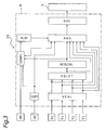
- conduits 3A and 3B are on the one hand connected with a master cylinder 2 actuated by a brake pedal 1 and are on the other hand connected, through a fluid pressure adjusting means 5, with conduits 6A, 6B, 6C and 6D leading to wheel brakes 7A, 7B, 7C and 7D of front left, front right, rear left and rear right wheels FL, FR, RL and RR, respectively.
- the conduit 3A is connected, via the fluid pressure adjusting means 5, with the conduit 6A and 6D leading to the wheel brakes 7A and 7D of the front left and rear right wheels FL and RR, respectively, while the conduit 3B is connected, by way of the fluid pressure adjusting means 5, with the conduits 6B and 6C leading to the wheel brakes 7B and 7C of the front right and rear left wheels FR and RL, respectively.
- the fluid pressure adjusting means 5 is of known type and increases, reduces or holds fluid pressure of the wheel brakes 7A to 7D in response to drive signals from a controller 9.
- Wheel speed sensors S0, S1, S2 and S3 output to the controller 9 pulse signals corresponding to rotational angular velocities of the front left, front right, rear left and rear right wheels FL, FR, RL and RR, respectively.
- the longitudinal acceleration sensor GS is arranged to detect longitudinal acceleration of a motor vehicle. As shown in Fig. 2, the longitudinal acceleration sensor GS is a gravity type acceleration sensor in which displacement amount of a vibrator F produced by acceleration is converted into an electrical signal by using a resistor, a piezo-electric element, a differential transformer or the like and this electrical signal (sensor output Am) is outputted to the controller 9. In the following description, sign of the sensor output Am of the longitudinal acceleration sensor GS is set to be positive for deceleration and negative for acceleration.
- a brake switch BS When a driver kicks the brake pedal 1, a brake switch BS is turned on and outputs to the controller 9 a signal indicating that the brake pedal 1 is being kicked, i.e., a signal indicative of ON state of the brake pedal 1.
- reference numeral 10 denotes an engine
- reference numerals 11A and 11B denote differential gears.
- the controller 9 includes a wheel speed calculating means VCAL, a wheel speed selecting means VSLCT, an estimated vehicle body acceleration calculating means GCELCAL, an antiskid control means ABS and a drive signal output means SOL.
- the controller 9 further includes a zero point correcting means COFF, a first comparative arithmetic means COMP1 and a fail-safe means FLSF.
- the wheel speed calculating means VCAL calculates wheel speeds V0, V1, V2 and V3 of the front left, front right, rear left and rear right wheels FL, FR, RL and RR on the basis of the pulse signals outputted by the wheel speed sensors S0, S1, S2 and S3, respectively.
- the calculated wheel speeds V0 to V3 are outputted to the wheel speed selecting means VSLCT and the antiskid control means ABS.
- the wheel speed selecting means VSLCT calculates a representative wheel speed V r for calculating an estimated vehicle body acceleration Aw to be described later.
- the representative wheel speed V r is calculated from the following equation (1).
- V r MAX (V0, V1, V2, V3) (1)
- symbol "MAX" represents that a maximum value in parentheses is selected.
- calculation method of the representative wheel speed V r is not restricted to the above equation (1).
- a second largest value in the wheel speeds V0, V1, V2 and V3 may also be employed as the representative wheel speed V r .
- the calculated representative wheel speed V r is outputted to the estimated vehicle body acceleration calculating means GCELCAL and the antiskid control means ABS.
- the representative wheel speed V r referred to above is differentiated with respect to time so as to calculate the estimated vehicle body acceleration Aw.
- sign of the estimated vehicle body acceleration Aw is set to be positive for deceleration and negative for acceleration.
- the estimated vehicle body acceleration Aw, the wheel speeds V0 to V3, the representative wheel speed V r and a corrected value Ac of detected vehicle body acceleration which is obtained by correcting zero point of the sensor output Am of the longitudinal acceleration sensor GS as will be described later are inputted to the antiskid control means ABS. From these factors, the antiskid control means ABS judges of pressure increase, pressure reduction or pressure holding for antiskid control. A signal of this judgement of pressure increase, pressure reduction or pressure holding by the antiskid control means ABS is outputted to the drive signal output means SOL.
- the fluid pressure adjusting means 5 is driven by a drive signal outputted from the drive signal output means SOL so as to increase, reduce or hold fluid pressure of the wheel brakes 7A to 7D.
- the antiskid control means ABS forms a judgement upon antiskid control by using the wheel speeds V0 to V3 and the corrected value Ac of detected vehicle body acceleration. Namely, the antiskid control means ABS compares vehicle body speed calculated from the corrected value Ac of detected vehicle body acceleration and the representative wheel speed V r with the wheel speeds V0 to V3 so as to detect skid symptom of the front left, front right, rear left and rear right wheels FL, FR, RL and RR.
- the antiskid control means ABS judges that any one of the front left, front right, rear left and rear right wheels FL, FR, RL and RR has skid symptom
- the antiskid control means ABS outputs the drive signal to the fluid pressure adjusting means 5 through the drive signal output means SOL so as to drive the fluid pressure adjusting means 5 such that fluid pressure of the corresponding one of the wheel brakes 7A to 7D is reduced.
- the antiskid control means ABS drives the fluid pressure adjusting means 5 through comparison between the vehicle body speed calculated from the corrected value Ac of detected vehicle body acceleration and the reprensentive wheel speed V r and the wheel speeds V0 to V3 so as to increase or hold fluid pressure of the wheel brakes 7A to 7D.
- the antiskid control means ABS forms a judgment upon antiskid control on the basis of the wheel speeds V0 to V3, the representative wheel speed V r and the estimated vehicle body acceleration Aw in place of the corrected value Ac of detected vehicle body acceleration.
- the antiskid control means ABS outputs to the first comparative arithmetic means COMP1 a signal indicating that antiskid control is being performed.
- the zero point correcting means COFF corrects zero point of the sensor output Am of the longitudinal acceleration sensor GS, which has changed by influences such as temperature, changes with time, inclination of road surface due to a slope, etc.
- zero point is corrected by a method described in Japanese Patent Laid-Open Publication No. 4-223275 (1992) filed by the present applicant as follows. Assuming that the estimated vehicle body acceleration Aw represents a real vehicle body acceleration, amount of zero point correction for the sensor output Am of the longitudinal acceleration sensor GS is (Aw - Am) and the sensor output Am of the longitudinal acceleration sensor GS is preferably drawn closer to the estimated vehicle body acceleration Aw as the motor vehicle is further free from excessive slip or spin of the wheels.
- the corrected value Ac of detected vehicle body acceleration is calculated by subjecting the sensor output Am of the longitudinal acceleration sensor GS to zero point correction of filtering shown in the following equation (2).
- Ao denotes correction amount.
- the correction amount Ao in the left member of the equation (2) represents correction amount in this control cycle, while the correction amount Ao in the right member of the equation (2) represents correction amount in the preceding control cycle.
- "r” denotes a constant for determining a speed for causing the corrected value Ac of detected vehicle body acceleration to follow the estimated vehicle body acceleration Aw.
- This constant r is set to be more than 0 and less than 1, i.e., 0 ⁇ r ⁇ 1 and is drawn closer to 0 and 1 as symptom of spin or slip of the wheels is more conspicuous and inconspicuous, respectively.
- sign of the corrected value Ac of detected vehicle body acceleration is to be positive for deceleration and negative for acceleration in the same manner as the sensor output Am of the longitudinal acceleration sensor GS and the estimated vehicle body acceleration Aw referred to earlier.
- the first comparative arithmetic mean COMP1 calculates ratio of the corrected value Ac of detected vehicle body acceleration to the estimated vehicle body acceleration Aw. When this ratio falls within a predetermined range, the first comparative arithmetic means COMP1 subtracts a predetermined value from a first integrating value T1. On the other hand, when the ratio falls out of the predetermined range, the first comparative arithmetic means COMP1 adds the predetermined value to the first integrating value T1. In each control cycle, this first integrating value T1 subjected to subtraction or addition is outputted to the fail-safe means FLSF.
- the fail-safe means FLSF outputs to the anti skid control means ABS the first prohibition signal D1 prohibiting use of the longitudinal acceleration sensor GS. Meanwhile, when the above first integrating value T1 is larger than a second predetermined value ⁇ 1 greater than the first predetermined value ⁇ 1, the fail-safe means FLSF outputs to the antiskid control means ABS a second prohibition signal D2 prohibiting antiskid control.
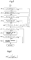
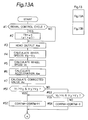
- processings of Figs. 4 and 5 are repeated at a predetermined period (control cycle) during a period from start of a power source upon turning on of an ignition switch to turning off of the ignition switch. Initially, if it is found at step #1 that it is an initial control cycle after start of the power source, an initial value of the first integrating value T1 is set to a value ⁇ 3 smaller than the first predetermined value ⁇ 1 at step #2.
- the first integrating value T1 is smaller than the first predetermined value ⁇ 1 at step #17 in several control cycles after turning on of the ignition switch and thus, the longitudinal acceleration sensor GS is securely used for antiskid control at an initial stage after turning on of the ignition switch.
- the zero point correcting means COFF reads the sensor output Am of the longitudinal acceleration sensor GS.
- the wheel speed calculating means VCAL calculates the wheel speeds V0, V1, V2 and V3 of the front left, front right, rear left and rear right wheels FL, FR, RL and RR on the basis of pulse signals from the wheel speed sensors S0, S1, S2 and S3.
- the wheel speed selecting means VSLCT calculates the representative wheel speed V r on the basis of the equation (1) referred to earlier.
- the estimated vehicle body acceleration calculating means GCELCAL calculates the estimated vehicle body acceleration Aw through linear differential of the representative wheel speed V r .
- the zero point correcting means COFF corrects zero point of the sensor output Am of the longitudinal acceleration sensor GS on the basis of the earlier mentioned equation (2) so as to calculate the corrected value Ac of detected vehicle body acceleration.
- step #8 Processings from step #8 to step #16 are performed by the first comparative arithmetic means COMP1. Initially, at step #8, it is judged based on presence and absence of an input signal from the brake switch BS whether or not the brake pedal 1 is being kicked by the driver, namely, the motor vehicle is being braked. In the case of "YES” at step #8, the program flow proceeds to step #9. On the contrary, in the case of "NO” at step #8, the program flow proceeds to step #10. At step #9, "1" is added to count of a braking timer STPTM for measuring period which has elapsed after start of braking of the motor vehicle. Meanwhile, at step #10, count of the braking timer STPTM is cleared to "0".
- step #11 it is judged whether or not count of the braking timer STPTM falls within a predetermined range, i.e., ⁇ 1 > STPTM ⁇ 1.
- a predetermined range i.e., ⁇ 1 > STPTM ⁇ 1.
- YES it is judged that a predetermined period has not elapsed from start of braking of the motor vehicle, so that the program flow proceeds to step #12.
- NO it is judged that the predetermined period has elapsed after start of braking of the motor vehicle, so that the program flow proceeds to step #17 by skipping steps #12-#16 for detecting failures of the longitudinal acceleration sensor GS.
- failures of the longitudinal acceleration sensor GS are detected only during the predetermined period after start of braking of the motor vehicle for the following reason. Namely, since the zero point correcting means COFF corrects zero point of the sensor output Am of the longitudinal acceleration sensor GS by comparing the sensor output Am and the estimated vehicle body acceleration Aw in each control cycle as described above, this zero point correction corrects also large-gain failure or small-gain failure of the longitudinal acceleration sensor GS. For example, if small-gain failure of the longitudinal acceleration sensor GS happens when the above described method of zero point correction is employed, the sensor output Am of the longitudinal acceleration sensor GS becomes small immediately after start of braking of the motor vehicle.
- the sensor output Am exhibits an apparently normal value during last half of braking of the motor vehicle. Accordingly, in the first embodiment, since comparative arithmetic operation for detecting failures of the longitudinal acceleration sensor GS by the first comparative arithmetic means COMP1 is permitted only during the predetermined period after start of braking of the motor vehicle, detection of failures of the longitudinal acceleration sensor GS is not performed in a region where large-gain failure or small-gain failure is corrected by zero point correction so as to be judged as being normal.
- the first comparative arithmetic means COMP1 judges based on a signal from the antiskid control means ABS whether or not the motor vehicle is being subjected to antiskid control.
- the program flow proceeds to step #13.
- the program flow proceeds to step #17. Failures of the longitudinal acceleration sensor GS are not detected during antiskid control of the motor vehicle as described above on the following ground. Namely, during antiskid control of the motor vehicle, since behaviors of the wheels are unstable, it is difficult to detect failures of the longitudinal acceleration sensor GS accurately.
- step #13 the program flow proceeds to step #14.
- step #13 the program flow proceeds to step #17.
- the estimated vehicle body acceleration Aw is smaller than the predetermined value g, namely, the motor vehicle is not under sufficient deceleration, it is difficult to detect failures of the longitudinal acceleration sensor GS with sufficiently high precision. Namely, when deceleration of the motor vehicle is insufficient, calculation error is apt to be large and thus, it is necessary to detect failures of the longitudinal acceleration sensor GS by eliminating this region of erroneous detection of failures of the longitudinal acceleration sensor GS.
- step #14 the ratio of the corrected value Ac of detected vehicle body acceleration to the estimated vehicle body acceleration Aw, i.e., (Ac/Aw) is calculated and it is judged whether or not the ratio (Ac/Aw) is smaller than a first predetermined value k1 (k1 > 1) but larger than a second predetermined value k2 (k2 ⁇ 1), namely, k1 > (Ac/Aw) > k2.
- k1 a first predetermined value
- k2 k2 ⁇ 1
- step #14 it is judged that the estimated vehicle body speed Aw and the corrected value Ac of detected vehicle body acceleration do not coincide with each other, namely, the corrected value Ac of detected vehicle body acceleration is far larger or smaller than the estimated vehicle body acceleration Aw, so that the program flow proceeds to step #16 at which "1" is added to the first integrating value T1.
- the first and second predetermined values k1 and k2 are determined by specifications of the longitudinal acceleration sensor GS such as scatter of quality of the longitudinal acceleration sensor GS at the time of its production.
- step #17 it is judged whether or not the first integrating value T1 is larger than the positive first predetermined value ⁇ 1.
- the program flow proceeds to step #18 at which the first prohibition signal D1 prohibiting use of the corrected value Ac of detected vehicle body acceleration based on output from the longitudinal acceleration sensor GS is outputted to the antiskid control means ABS.
- the antiskid control means ABS performs antiskid control by using the estimated vehicle body acceleration Aw without using the corrected value Ac of detected vehicle body acceleration.
- step #19 it is judged whether or not the first integrating value T1 is larger than the second predetermined value ⁇ 1 greater than the first predetermined value ⁇ 1.
- the program flow proceeds to step #20 at which the second prohibition signal D2 prohibiting antiskid control is outputted to the antiskid control means ABS.
- the apparatus K1 for detecting failures of the longitudinal acceleration sensor GS if the ratio (Ac/Aw) of the corrected value Ac of detected vehicle body acceleration to the estimated vehicle body acceleration Aw falls out of the range bounded by the first and second predetermined values k1 and k2, it is judged that the corrected value Ac of detected vehicle body acceleration is far larger or smaller than the estimated vehicle body acceleration Aw, so that "1" is added to the first integrating value T1.
- the ratio (Ac/Aw) falls within the range bounded by the first and second predetermined values k1 and k2, "1" is subtracted from the first integrating value T1.
- step #2 for setting an initial value of the first integrating value T1 may be replaced by step #21 shown in Fig. 6.
- the initial value of the first integrating value T1 is set to a value ⁇ 4 intermediate between the first and second predetermined values ⁇ 1 and ⁇ 1, namely, ⁇ 1 > ⁇ 4 > ⁇ 1..
- use of the longitudinal acceleration sensor GS is prohibited at steps #17 and #18 even when the longitudinal acceleration sensor GS is functioning normally.
- the first integrating value T1 is reduced to not more than the first predetermined value ⁇ 1, i.e., T1 ⁇ ⁇ 1 and thus, prohibition of use of the longitudinal acceleration sensor GS is withdrawn.
- the first integrating value T1 is further increased through subsequent repetition of several control cycles. Therefore, if the initial value of the first integrating value T1 is set as described above, use of the longitudinal acceleration sensor GS can be prohibited positively from a time point immediately after start of the motor vehicle in case the longitudinal acceleration sensor GS has failures.
- the controller 9 of the apparatus K2 includes second and third comparative arithmetic means COMP2 and COMP3 in place of the first comparative arithmetic means COMP1 of the apparatus K1.
- signals from the brake switch BS, the zero point correcting means COFF and the estimated vehicle body acceleration calculating means GCELCAL are inputted to the second and third comparative arithmetic means COMP2 and COMP3.
- the second comparative arithmetic means COMP2 calculates a ratio (Ac/Aw) of the corrected value Ac of detected vehicle body acceleration to the estimated vehicle body acceleration Aw. If this ratio (Ac/Aw) falls within a predetermined range, a predetermined value is added to a second integrating value T2.
- the third comparative calculating means COMP3 calculates the ratio (Ac/Aw) of the corrected value Ac of detected vehicle body acceleration to the estimated vehicle body acceleration Aw.
- this ratio (Ac/Aw) falls out of the predetermined range, the predetermined value is added to a third integrating value T3. Since other constructions of the apparatus K2 are similar to those of the apparatus K1, the description is abbreviated for the sake of brevity.
- an initial value of the second integrating value T2 is set to t2 and an initial value of the third integrating value T3 is set to t3.
- These initial values t2 and t3 are set such that their ratio (t3/t2) falls between third and fourth predetermined values ⁇ 2 and ⁇ 2 ( ⁇ 2 > ⁇ 2) to be described later.
- the second and third integrating values T2 and T3 are set as described above, use of the longitudinal acceleration sensor GS is prohibited at steps #37 and #38 during a predetermined period after start of running of the motor vehicle even if the longitudinal acceleration sensor GS is functioning normally. Meanwhile, if the longitudinal acceleration sensor GS is functioning normally, the second integrating value T2 becomes larger than the third integrating value T3 through subsequent repetition of several control cycles and thus, prohibition of use of the longitudinal acceleration sensor GS is withdrawn. On the other hand, in case the longitudinal acceleration sensor GS has failures essentially, the third integrating value T3 is further increased through subsequent repetition of several control cycles.
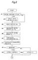
- step #34 of Fig. 9 the ratio (Ac/Aw) of the corrected value Ac of detected vehicle body acceleration to the estimated vehicle body acceleration Aw is calculated and it is judged whether or not the ratio (Ac/Aw) is smaller than the first predetermined value k1 but larger than the second predetermined value k2. In the case of "YES" at step #34, it is judged that the corrected value Ac of detected vehicle body acceleration coincides with the estimated vehicle body acceleration Aw, so that the program flow proceeds to step #35.
- step #34 it is judged that the corrected value Ac of detected vehicle body acceleration is far larger or smaller than the estimated vehicle body acceleration Aw, so that the program flow proceeds to step #36.
- step #35 "1" is added to the second integrating value T2.
- step #36 "1" is added to the third integrating value T3.
- a ratio (T3/T2) of the third integrating value T3 to the second integrating value T2 is larger than the third predetermined value ⁇ 2.
- This ratio (T3/T2) represents a ratio of a period during which the corrected value Ac of detected vehicle body acceleration does not coincide with the estimated vehicle body acceleration Aw to a period during which the corrected value Ac of detected vehicle body acceleration coincides with the estimated vehicle body acceleration Aw.
- the program flow proceeds to step #38.
- the first prohibition signal D1 prohibiting use of the corrected value Ac of detected vehicle body acceleration based on output from the longitudinal acceleration sensor GS is outputted to the antiskid control means ABS.
- step #39 it is judged whether or not the ratio (T3/T2) of the third integrating value T3 to the second integrating value T2 is larger than the fourth predetermined value ⁇ 2.
- the program flow proceeds to step #40 at which the second prohibition signal D2 prohibiting antiskid control is outputted to the antiskid control means ABS.
- failures of the longitudinal acceleration sensor GS are detected on the basis of the ratio (T3/T2) of the third integrating value T3 subjected to addition when the corrected value Ac of detected vehicle body acceleration is far larger or smaller than the estimated vehicle body acceleration Aw to the second integrating value T2 subjected to addition when the corrected value Ac of detected vehicle body acceleration coincides with the estimated vehicle body acceleration Aw. Therefore, not only in the case of large-gain failure of the longitudinal acceleration sensor GS but in the case of small-gain failure of the longitudinal acceleration sensor GS, it is possible to detect failures of the longitudinal acceleration sensor GS positively.
- step #31 of Fig. 8 may be replaced by step #41 of Fig. 10.
- step #41 the initial value of the second integrating value T2 is set to "0" and the initial value of the third integrating value T3 is also set to "0". If the initial values of the second and third integrating values T2 and T3 are set as described above when the longitudinal acceleration sensor GS is functioning normally, the second integrating value T2 is subjected to addition at step #35 and thus, the longitudinal acceleration sensor GS can be used positively from a time point immediately after start of the motor vehicle.
- step #35 of Fig. 9 may be replaced by steps #42 and #35 of Fig. 11.
- the second integrating value T2 is subjected to addition up to a maximum value t2M.
- the third integrating value T3 is subjected to addition. Therefore, time period required for the ratio (T3/T2) to exceed the third predetermined value ⁇ 2 or the fourth predetermined value ⁇ 2 is shortened and thus, failures of the longitudinal acceleration sensor GS can be detected promptly.
- an apparatus K3 for detecting failures of the longitudinal acceleration sensor GS, according to a third embodiment of the present invention is described with reference to Fig. 12.
- signals from the estimated vehicle body acceleration calculating means GCELCAL, the zero point correcting means COFF, the brake switch BS and the antiskid control means ABS are inputted to the first comparative arithmetic means COMP1 in the same manner as the first embodiment.
- the wheel speeds V0 to V3 from the wheel speed calculating means VCAL are also inputted to the first comparative arithmetic means COMP1.
- the first comparative arithmetic means COMP1 includes a first means for detecting from the wheel speeds V0 to V3 whether or not the motor vehicle is turning. When the motor vehicle is not turning, the first comparative arithmetic means COMP1 performs addition or subtraction for the first integrating value T1. On the other hand, when the motor vehicle is turning, the first comparative arithmetic means COMP1 does not perform addition or subtraction for the first integrating value T1.
- the first comparative arithmetic means COMP1 further includes a second means for judging from the wheel speeds V0 to V3 whether or not the front left, front right, rear left and rear right wheels FL, FR, RL and RR are spinning.
- the first comparative arithmetic means COMP1 When the second means has judged that the front left, front right, rear left and rear right wheels FL, FR, RL and RR are not spinning, the first comparative arithmetic means COMP1 performs addition or subtraction for the first integrating value T1. On the contrary, when the front left, front right, rear left and rear right wheels FL, FR, RL and RR are spinning, the first comparative arithmetic means COMP1 does not perform addition or subtraction for the first integrating value T1. Since other constructions of the apparatus K3 are similar to those of the apparatus K1, the description is abbreviated for the sake of brevity.
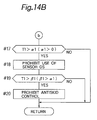
- step #51 it is judged if not only the wheel speed V1 of the front right wheel FR is larger than the wheel speed V0 of the front left wheel FL but the wheel speed V3 of the rear right wheel RR is larger than the wheel speed V2 of the rear left wheel RL.
- step #52 it is judged if not only the wheel speed V1 of the front right wheel FR is larger than the wheel speed V0 of the front left wheel FL but the wheel speed V3 of the rear right wheel RR is larger than the wheel speed V2 of the rear left wheel RL.
- step #53 it is judged if not only the wheel speed V0 of the front left wheel FL is larger than the wheel speed V1 of the front right wheel FR and the wheel speed V2 of the rear left wheel RL is larger than the wheel speed V3 of the rear right wheel RR.
- step #52 it is judged if both of the following equations (5) and (6) are satisfied.
- step #53 the program flow proceeds to step #54.
- step #52 "1" is added to count of a turning timer CORTM for measuring duration of turning of the motor vehicle.
- step #54 "1" is subtracted from count of the turning timer CORTM.
- step #55 it is judged whether or not count of the turning timer CORTM is smaller than a predetermined value ⁇ .
- a predetermined value ⁇ it is judged that the motor vehicle is not turning, in other words, the motor vehicle is running straightforwardly, so that the program flow proceeds to step #56.
- "NO" at step #55 it is judged that the motor vehicle is turning, so that the program flow proceeds to step #17 without performing addition or subtraction for the first integrating value T1.
- the wheel speeds V0 to V3 of the wheels FL, FR, RL and RR disposed outside a curved locus drawn by the motor vehicle during its turning become larger than speed of center of gravity of the motor vehicle, while the wheel speeds V0 to V3 of the wheels FL, FR, RL and RR disposed inside the locus become smaller than speed of center of gravity of the motor vehicle. Therefore, the estimated vehicle body acceleration Aw calculated from the wheel speeds V0 to V3 does not approximate to actual vehicle body acceleration exactly. Consequently, during turning of the motor vehicle, it is difficult to detect failures of the longitudinal acceleration sensor GS at high accuracy.
- step #63 it is judged at step #63 whether or not count of the spin timer SPTM is smaller than a positive predetermined value ⁇ . In the case of "YES” at step #63, it is judged that the wheels FL, FR, RL and RR are not spinning, so that the program flow proceeds to step #8. On the other hand, in the case of "NO” at step #63, it is judged that the wheels FL, FR, RL and RR are spinning, so that the program flow proceeds to step #17 without performing addition or subtraction for the first integrating value T1.
- Steps #14 to #16 of the first and third embodiments may be replaced by steps #71 to #77 shown in Fig. 15.
- step #14 it is judged whether or not the ratio (Ac/Aw) of the corrected value Ac of detected vehicle body acceleration to the estimated vehicle body acceleration Aw is smaller than the first predetermined value k1 but larger than the second predetermined value k2.
- "1" is subtracted from the first integrating value T1 at step #15.
- "NO" at step #14 "1" is added to the first integrating value T1 at step #16.
- step #71 it is judged whether or not the ratio (Ac/Aw) is smaller than the first predetermined value k1 but larger than the second predetermined value k2. In the case of "YES” at step #71, "1" is subtracted from the first integrating value T1 at step #72.
- step #73 it is judged at step #73 whether or not the ratio (Ac/Aw) is smaller than a fourth predetermined value k4.
- step #74 the program flow proceeds to step #74 at which "3" is added to the first integrating value T1.
- step #75 it is judged whether or not the ratio (Ac/Aw) is smaller than a third predetermined value k3.
- step #76 the program flow proceeds to step #76 at which "2" is added to the first integrating value T1.
- step #75 the program flow proceeds to step #77 at which "1" is added to the first integrating value T1.
- the second, third and fourth predetermined values k2, k3 and k4 are set so as to satisfy relation of (k4 ⁇ k3 ⁇ k2).
- step #71 to step #77 it is possible to detect failures of the longitudinal acceleration sensor GS earlier in case degree of small-gain failure of the longitudinal acceleration sensor GS, which adversely affects the system serously, especially, increase of stopping distance is high.
- an apparatus K4 for detecting failures of the longitudinal acceleration sensor GS, according to a fourth embodiment of the present invention is described with reference to Fig. 16.
- signals from the estimated vehicle body acceleration calculating means GCELCAL, the zero point correcting means COFF, the brake switch BS and the antiskid control means ABS are inputted to the second and third comparative arithmetic means COMP2 and COMP3 in the same manner as the second embodiment.
- the wheel speeds V0 to V3 from the wheel speed calculating means VCAL are also inputted to the second and third comparative arithmetic means COMP2 and COMP3.
- the second comparative arithmetic means COMP2 detects from the wheel speeds V0 to V3 whether or not the motor vehicle is turning. When the motor vehicle is not turning, the second comparative arithmetic means COMP2 performs addition for the second integrating value T2. On the other hand, when the motor vehicle is turning, the second comparative arithmetic means COMP2 does not perform this processing. Meanwhile, the second comparative arithmetic means COMP2 judges from the wheel speeds V0 to V3 whether or not the wheels FL, FR, RL and RR are spinning. When judging that the wheels FL, FR, RL and RR are not spinning, the second comparative arithmetic means COMP2 performs addition for the second integrating value T2. On the contrary, when judging that the wheels FL, FR, RL and RR are spinning, the second comparative arithmetic means COMP2 does not perform this processing.
- the third comparative arithmetic means COMP3 detects from the wheel speeds V0 to V3 whether or not the motor vehicle is turning. When the motor vehicle is not turning, the third comparative arithmetic means COMP3 performs addition for the third integrating value T3. On the contrary, when the motor vehicle is turning, the third comparative arithmetic means COMP3 does not perform this processing. Meanwhile, the third comparative arithmetic means COMP3 judges from the wheel speeds V0 to V3 whether or not the wheels FL, FR, RL and RR are spinning. When judging that the wheels FL, FR, RL and RR are not spinning, the third comparative arithmetic means COMP3 performs addition for the third integrating value T3.
- the third comparative arithmetic means COMP3 does not perform this processing. Since other constructions of the apparatus K4 are similar to those of the apparatus K2, the description is abbreviated for the sake of brevity.
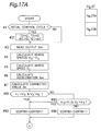
- step #81 it is judged if not only the wheel speed V1 of the front right wheel FR is larger than the wheel speed V0 of the front left wheel FL but the wheel speed V3 of the rear right wheel RR is larger than the wheel speed V2 of the rear left wheel RL.
- step #82 the program flow proceeds to step #82.
- step #83 the program flow proceeds to step #83.
- step #83 it is judged if not only the wheel speed V0 of the front left wheel FL is larger than the wheel speed V1 of the front right wheel FR but the wheel speed V2 of the rear left wheel RL is larger than the wheel speed V3 of the rear right wheel RR.
- the program flow proceeds to step #82.
- "NO" at step #83 namely, when at least one of the equations (5) and (6) is not satisfied, the program flow proceeds to step #84.
- step #82 "1" is added to count of the turning timer CORTM for measuring duration of turning of the motor vehicle.
- step #84 "1" is subtracted from count of the turning timer CORTM.
- step #85 it is judged whether or not count of the turning timer CORTM is smaller than the predetermined value ⁇ .
- the program flow proceeds to step #86.
- the program flow proceeds to step #37 without performing addition for the second and third integrating values T2 and T3.
- step #87 the wheel acceleration WA i is calculated through linear differential of the wheel speeds V0 to V3. Then, at step 88, it is judged whether or not absolute value of the wheel acceleration WA i is larger than the predetermined value ⁇ . In the case of "YES” at step #88, the program flow proceeds to step #89. On the other hand, in the case of "NO” at step #88, the program flow proceeds to step #90. At step #89, "1" is added to count of the spin timer SPTM. Meanwhile, at step #90, "1" is subtracted from count of the spin timer SPTM.
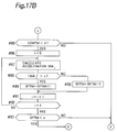
- step #93 it is judged whether or not count of the spin timer SPTM is smaller than the predetermined value ⁇ .
- the program flow proceeds to step #8.
- the case of "NO” at step #93 it is judged that the wheels FL, FR, RL and RR are spinning, so that the program flow proceeds to step #37 without performing addition for the second and third integrating values T2 and T3. processings from step #8 to step #40 of Figs. 18A and 18B are identical with those of the second embodiment.
- failures of the longitudinal acceleration sensor GS are detected and are not detected when the motor vehicle is not turning and is turning, respectively in the same manner as the third embodiment. Therefore, such adverse influence that accuracy of outputs of the longitudinal acceleration sensor GS and the estimated vehicle body acceleration Aw drops at the time of turning of the motor vehicle is eliminated and thus, it is possible to detect failures of the longitudinal acceleration sensor GS more accurately.
- failures of the longitudinal acceleration sensor GS are detected and are not detected when the wheels FL, FR, RL and RR are not spinning and are spinning, respectively in the same manner as the third embodiment. Therefore, such adverse influence that the estimated vehicle body acceleration Aw becomes inaccurate at the time of spinning of the wheels FL, FR, RL and RR is obviated and thus, it is possible to detect failures of the longitudinal acceleration sensor GS more accurately.
- Steps #34 to #36 of the second and fourth embodiments may be replaced by steps #101 to #107 shown in Fig. 19.
- the ratio (Ac/Aw) is calculated and it is judged whether or not the ratio (Ac/Aw) is smaller than the first predetermined value k1 but larger than the second predetermined value k2.
- "1" is added to the second integrating value T2 at step #35.
- "NO" at step #34 "1" is added to the third integrating value T3 at step #36.
- steps #101 to #107 if the ratio (Ac/Aw) is not more than the second predetermined value k2, a value selected from a plurality of addends in accordance with value of the ratio (Ac/Aw) is added to the third integrating value T3.
- step #101 it is judged whether or not the ratio (Ac/Aw) is smaller than the first predetermined value k1 but larger than the second predetermined value k2. In the case of "YES" at step #101, "1" is added to the second integrating value T2 at step #102.
- step #103 it is judged at step #103 whether or not the ratio (Ac/Aw) is smaller than the fourth predetermined value k4. In the case of "YES” at step #103, the program flow proceeds to step #104. Meanwhile, in the case of "NO” at step #103, the program flow proceeds to step #105.
- step #104 "3" is added to the third integrating value T3. Meanwhile, at step #105, it is judged whether or not the ratio (Ac/Aw) is smaller than the third predetermined value k3. In the case of "YES” at step #105, the program flow proceeds to step #106. On the other hand, in the case of "NO” at step #105, the program flow proceeds to step #107. At step #106, "2" is added to the third integrating value T3. Meanwhile, at step #107, "1" is added to the third integrating value T3. As described earlier with reference to Fig. 15, the second, third and fourth predetermined values k2, k3 and k4 are set so as to satisfy relation of (k4 ⁇ k3 ⁇ k2).
- step #107 when processings from step #101 to step #107 are performed, it is possible to detect failures of the longitudinal acceleration sensor GS earlier when degree of small-gain failure of the longitudinal acceleration sensor GS, which adversely affects the system seriously, especially, increase of stopping distance is high.
- the present invention is not restricted to the above described embodiments but may be modified variously.
- the first to third comparative arithmetic means COMP1 to COMP3 are arranged to measure period from start of braking in response to signals inputted from the brake switch BS but may be adapted to judge that braking starts at the time when the estimated vehicle body acceleration Aw has reached a predetermined value.
- the zero point correcting means COFF may be arranged to correct zero point of the sensor output Am of the longitudinal acceleration sensor GS by setting to zero point the sensor output Am obtained at the time when the motor vehicle is running at a constant speed.
- the longitudinal acceleration sensor GS since small-gain failure and large-gain failure of the longitudinal acceleration sensor GS are not corrected by correction of zero point of the sensor output Am of the longitudinal acceleration sensor GS in contrast with zero point correction of the first to fourth embodiments, comparative arithmetic operation is not required to be restricted to the predetermined period from start of braking.
- the corrected value Ac of detected vehicle body acceleration which is obtained from the longitudinal acceleration sensor GS, is used for antiskid control in the foregoing embodiments but may also be used for other control purposes, for example, control of distribution of driving force to the front and rear wheels, active suspension control, etc.
- the first and third comparative arithmetic means COMP1 and COMP3 select a larger value from a plurality of addends and add the larger value to the first and third integrating values T1 and T3, respectively. In this case, large-gain failure of the longitudinal acceleration sensor can be detected earlier.
- the ratio of the vehicle body acceleration calculated from the output of the longitudinal acceleration sensor to the estimated vehicle body acceleration is calculated and the first integrating value is calculated by performing the subtraction and the addition for the first integrating value when the ratio falls within and out of the predetermined range, respectively. If the first integrating value is larger than the predetermined value, the predetermined fail-safe processing is performed. Therefore, also in the case of small-gain failure and large-gain failure of the longitudinal acceleration sensor, it is possible to detect failures of the longitudinal acceleration sensor positively.
- the first integrating value is calculated by performing the subtraction and the addition for the first integrating value in accordance with the ratio of the vehicle body acceleration calculated from the output of the longitudinal acceleration sensor to the estimated vehicle body acceleration. If the first integrating value is larger than the predetermined value, the predetermined fail-safe processing is performed. Therefore, since such adverse influence brought about by turning of the motor vehicle and spin of the wheels as drop of accuracy of outputs of the longitudinal acceleration sensor and the wheel speed sensors is eliminated, it is possible to detect failures of the longitudinal acceleration sensor more accurately.
- the value selected from a plurality of the addends in accordance with the ratio is added to the first integrating value.
- the ratio becomes smaller, the larger value is selected from the addends and is added to the first integrating value. In this case, it becomes possible to detect small-gain failure of the longitudinal acceleration sensor earlier.
- the addition for the second integrating value is performed when the first ratio of the vehicle body acceleration calculated from the output of the longitudinal acceleration sensor to the estimated vehicle body acceleration falls within the predetermined range, while the addition for the third integrating value is performed when the first ratio falls out of the predetermined range. Furthermore, if the second ratio of the third integrating value to the second integrating value is larger than the predetermined value, the predetermined fail-safe processing is performed. Therefore, also in the case of small-gain failure and large-gain failure of the longitudinal acceleration sensor, it is possible to detect failures of the longitudinal acceleration sensor positively.
- the addition for the second and third integrating values is performed in accordance with the first ratio. Furthermore, if the second ratio is larger than the predetermined value, the predetermined fail-safe processing is performed. Therefore, such adverse influence brought about by turning of the motor vehicle and spin of the wheels as drop of accuracy of outputs of the longitudinal acceleration sensor and the wheel speed sensors is eliminated and thus, it is possible to detect failures of the longitudinal acceleration sensor more accurately.
- the value selected from a plurality of the addends in accordance with the first ratio is added to the third integrating value. Therefore, it is possible to detect large-gain failure of the longitudinal acceleration sensor early.
- the apparatuses K2 and K4 of Claims 23 and 24 as the first ratio becomes smaller, the larger value is selected from the addends and is added to the third integrating value. Thus, in this case, small-gain failure of the longitudinal acceleration sensor can be detected earlier.
Landscapes
- Engineering & Computer Science (AREA)
- Transportation (AREA)
- Mechanical Engineering (AREA)
- Regulating Braking Force (AREA)
Abstract

Description
- The present invention generally relates to an apparatus for detecting failures of a longitudinal acceleration sensor for detecting longitudinal acceleration of a motor vehicle and more particularly, to an apparatus which is capable of detecting not only a small-gain failure that output of the longitudinal acceleration sensor is smaller than actual acceleration of the motor vehicle but a large-gain failure that output of the longitudinal acceleration sensor is larger than actual acceleration of the motor vehicle and is properly used for an antiskid control system.
- Conventionally, in order to improve control accuracy of an antiskid control system, it has been proposed to utilize signals from a longitudinal acceleration sensor for detecting longitudinal acceleration of a motor vehicle. The antiskid control system performs control on the premise that the longitudinal acceleration sensor is normal. Therefore, in case failures of the longitudinal acceleration sensor happen such that output value of the longitudinal acceleration sensor is smaller or larger than actual acceleration or deceleration of the motor vehicle, performance of the antiskid control system in which the signals from the longitudinal acceleration sensor are used as control data deteriorates greatly.
- For example, in an antiskid control system in which the signals from the longitudinal acceleration sensor are used for performing estimated calculation of vehicle body speed, brake fluid pressure is reduced, increased or held on the basis of wheel speed which is calculated from vehicle body speed estimated from signals outputted by the longitudinal acceleration sensor and output of wheel speed sensors. Therefore, if vehicle body speed calculated from output of the longitudinal acceleration sensor is different from actual vehicle body speed, such problems arise that braking distance increases due to insufficient brake fluid pressure or wheels are locked due to excessive brake fluid pressure.
- In order to solve these problems, an apparatus for detecting failures of the longitudinal acceleration sensor has been proposed so far. For example, Japanese Patent Laid-Open Publication No. 2-284968 (1990) proposes an apparatus which, if it is found that output of a longitudinal acceleration sensor has a value indicative of acceleration or deceleration of a motor vehicle when the motor vehicle is running at a constant speed, judges the longitudinal acceleration sensor to be defective so as to perform fail-safe processing.
- However, this known apparatus is capable of detecting failures of the longitudinal acceleration sensor in case output is generated from the longitudinal acceleration sensor in spite of a state that the motor vehicle is neither accelerated nor decelerated or in case output of the longitudinal acceleration sensor is larger than actual acceleration or deceleration of the motor vehicle (large-gain failure). On the other hand, the known apparatus is not capable of detecting failures of the longitudinal acceleration sensor when output is not generated from the longitudinal acceleration sensor in spite of a state that the motor vehicle is being accelerated or decelerated or when output of the longitudinal acceleration sensor is smaller than actual acceleration or deceleration of the motor vehicle (small-gain failure). Therefore, in an antiskid control system incorporating the known apparatus, in case small-gain failure happens, it is judged that road surface has low coefficient µ of friction even if road surface actually has high coefficient µ of friction, so that control for road surface having low coefficient µ of friction is performed, thereby resulting in increase of stopping distance, etc.
- Meanwhile, Japanese Patent Laid-Open Publication No. 4-110267 (1992) proposes an apparatus for detecting failures of a longitudinal acceleration sensor and a transverse acceleration sensor for detecting transverse acceleration of a motor vehicle. When it is found that output of the longitudinal acceleration sensor has a value indicative of acceleration or deceleration of the motor vehicle when the motor vehicle is running at a constant speed, the apparatus judges the longitudinal acceleration sensor to be defective. Meanwhile, if output level of the transverse acceleration sensor is not less than a predetermined level when there is no difference among wheel speeds of respective wheels, namely, the motor vehicle is running straight-forwardly, the apparatus judges the transverse acceleration sensor to be defective. Furthermore, in case output level of the transverse acceleration sensor is less than the predetermined level when difference between wheel speeds of the left and right wheels is not less than a predetermined value, namely, the motor vehicle is turning, the apparatus judges the transverse acceleration sensor to be defective.
- However, in this prior art apparatus, the transverse acceleration sensor is capable of detecting both large-gain failure and small-gain failure but the longitudinal acceleration sensor is not capable of detecting small-gain failure. Therefore, in this prior art apparatus, the same problem as that of the above mentioned known apparatus arises.
- Accordingly, an essential object of the present invention is to provide, with a view to eliminating the drawbacks inherent in conventional apparatuses, an apparatus which is capable of detecting both large-gain failure and small-gain failure of a longitudinal acceleration sensor.
- In order to accomplish this object of the present invention,
Claim 1 provides an apparatus for detecting failures of a longitudinal acceleration sensor for detecting a longitudinal acceleration of a motor vehicle, according to a first embodiment of the present invention comprising: a wheel speed calculating means for calculating wheel speeds on the basis of outputs of wheel speed sensors; an estimated vehicle body acceleration calculating means for calculating an estimated vehicle body acceleration on the basis of the wheel speeds; a comparative arithmetic means which calculates a ratio of a vehicle body acceleration calculated from an output of the longitudinal acceleration sensor to the estimated vehicle body acceleration and calculates a first integrating value by performing a subtraction and an addition for the first integrating value when the ratio falls within and out of a predetermined range, respectively; and a fail-safe means for performing a predetermined fail-safe processing if the first integrating value is larger than a predetermined value. - In this apparatus, also in the case of small-gain failure and large-gain failure of the longitudinal acceleration sensor, it is possible to detect failures of the longitudinal acceleration sensor positively.
- Meanwhile, Claim 2 provides an apparatus for detecting failures of a longitudinal acceleration sensor for detecting a longitudinal acceleration of a motor vehicle, according to a third embodiment of the present invention comprising: a wheel speed calculating means for calculating wheel speeds on the basis of outputs of wheel speed sensors; an estimated vehicle body acceleration calculating means for calculating an estimated vehicle body acceleration on the basis of the wheel speeds; a comparative arithmetic means which includes a first means for detecting that the motor vehicle is turning and a second means for detecting that wheels are spinning; wherein in case not only the motor vehicle is not turning but the wheel are not spinning, the comparative arithmetic means calculates a ratio of a vehicle body acceleration calculated from an output of the longitudinal acceleration sensor to the estimated vehicle body acceleration and calculates a first integrating value by performing a subtraction and an addition for the first integrating value when the ratio falls within and out of a predetermined range, respectively; and a fail-safe means for performing a predetermined fail-safe processing if the first integrating value is larger than a predetermined value.
- In this apparatus, since such adverse influence brought about by turning of the motor vehicle and spin of the wheels as drop of accuracy of outputs of the longitudinal acceleration sensor and the wheel speed sensors is eliminated, it is possible to detect failures of the longitudinal acceleration sensor more accurately.
- Furthermore,
Claim 8 provides an apparatus for detecting failures of a longitudinal acceleration sensor for detecting a longitudinal acceleration of a motor vehicle, according to a second embodiment of the present invention comprising: a wheel speed calculating means for calculating wheel speeds on the basis of outputs of wheel speed sensors; an estimated vehicle body acceleration calculating means for calculating an estimated vehicle body acceleration on the basis of the wheel speeds; a comparative arithmetic means which calculates a first ratio of a vehicle body acceleration calculated from an output of the longitudinal acceleration sensor to the estimated vehicle body acceleration and calculates second and third integrating values by performing an addition for the second and third integrating values when the first ratio falls within and out of a predetermined range, respectively; and a fail-safe means for performing a predetermined fail-safe processing if a second ratio of the third integrating value to the second integrating value is larger than a predetermined value. - In this apparatus, also in the case of small-gain failure and large-gain failure of the longitudinal acceleration sensor, it is possible to detect failures of the longitudinal acceleration sensor positively.
- In addition,
Claim 9 provides an apparatus for detecting failures of a longitudinal acceleration sensor for detecting a longitudinal acceleration of a motor vehicle, according to a fourth embodiment of the present invention comprising: a wheel speed calculating means for calculating wheel speeds on the basis of outputs of wheel speed sensors; an estimated vehicle body acceleration calculating means for calculating an estimated vehicle body acceleration on the basis of the wheel speeds; a comparative arithmetic means which includes a first means for detecting that the motor vehicle is turning and a second means for detecting that wheels are spinning; wherein in case not only the motor vehicle is not turning but the wheels are not spinning, the comparative arithmetic means calculates a first ratio of a vehicle body acceleration calculated from an output of the longitudinal acceleration sensor to the estimated vehicle body acceleration and calculates second and third integrating values by performing an addition for the second and third integrating values when the first ratio falls within and out of a predetermined range, respectively; and a fail-safe means for performing a predetermined fail-safe processing if a second ratio of the third integrating value to the second integrating value is larger than a predetermined value. - In this apparatus, since such adverse influence brought about by turning of the motor vehicle and spin of the wheels as drop of accuracy of outputs of the longitudinal acceleration sensor and the wheel speed sensors is obviated, it is possible to detect failures of the longitudinal acceleration sensor more accurately.
- This object and features of the present invention will become apparent from the following description taken in conjunction with the preferred embodiments thereof with reference to the accompanying drawings, in which:
- Fig. 1 is a schematic view of an antiskid control system including an apparatus for detecting failures of a longitudinal acceleration sensor, according to a first embodiment of the present invention;
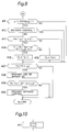
- Fig. 2 is a schematic view of the longitudinal acceleration sensor of Fig. 1;
- Fig. 3 is a schematic view of the apparatus of Fig. 1;
- Figs. 4 and 5 are flow charts showing operational sequences of the apparatus of Fig. 1;
- Fig. 6 is a flow chart showing a modification of the flow chart of Fig. 4;
- Fig. 7 is a schematic view of an apparatus for detecting failures of a longitudinal acceleration sensor, according to a second embodiment of the present invention;
- Figs. 8 and 9 are flow charts showing operational sequences of the apparatus of Fig. 7;
- Fig. 10 is a flow chart showing a modification of the flow chart of Fig. 8;
- Fig. 11 is a flow chart showing a modification of the flow chart of Fig. 9;
- Fig. 12 is a schematic view of an apparatus for detecting failures of a longitudinal acceleration sensor, according to a third embodiment of the present invention;
- Figs. 13A and 13B and 14A and 14B are flow charts showing operational sequences of the apparatus of Fig. 12;
- Fig. 15 is a flow chart showing a modification of the first and third embodiments of the present invention;
- Fig. 16 is a schematic view of an apparatus for detecting failures of a longitudinal acceleration sensor, according to a fourth embodiment of the present invention;
- Figs. 17A and 17B and 18A and 18B are flow charts showing operational sequences of the apparatus of Fig. 16; and
- Fig. 19 is a flow chart showing a modification of the second and fourth embodiments of the present invention.
- Before the description of the present invention proceeds, it is to be noted that like parts are designated by like reference numerals throughout several views of the accompanying drawings.
-
- Referring now to the drawings, there is shown in Figs. 1 to 3, an antiskid control system including an apparatus K1 for detecting failures of a longitudinal acceleration sensor GS, according to a first embodiment of the present invention. In the antiskid control system,
conduits master cylinder 2 actuated by abrake pedal 1 and are on the other hand connected, through a fluid pressure adjusting means 5, withconduits wheel brakes conduit 3A is connected, via the fluid pressure adjusting means 5, with theconduit wheel brakes conduit 3B is connected, by way of the fluid pressure adjusting means 5, with theconduits wheel brakes - The fluid pressure adjusting means 5 is of known type and increases, reduces or holds fluid pressure of the
wheel brakes 7A to 7D in response to drive signals from acontroller 9. Wheel speed sensors S₀, S₁, S₂ and S₃ output to thecontroller 9 pulse signals corresponding to rotational angular velocities of the front left, front right, rear left and rear right wheels FL, FR, RL and RR, respectively. - The longitudinal acceleration sensor GS is arranged to detect longitudinal acceleration of a motor vehicle. As shown in Fig. 2, the longitudinal acceleration sensor GS is a gravity type acceleration sensor in which displacement amount of a vibrator F produced by acceleration is converted into an electrical signal by using a resistor, a piezo-electric element, a differential transformer or the like and this electrical signal (sensor output Am) is outputted to the
controller 9. In the following description, sign of the sensor output Am of the longitudinal acceleration sensor GS is set to be positive for deceleration and negative for acceleration. - When a driver kicks the
brake pedal 1, a brake switch BS is turned on and outputs to the controller 9 a signal indicating that thebrake pedal 1 is being kicked, i.e., a signal indicative of ON state of thebrake pedal 1. Meanwhile, in Fig. 1,reference numeral 10 denotes an engine, whilereference numerals - As shown in Fig. 3, the
controller 9 includes a wheel speed calculating means VCAL, a wheel speed selecting means VSLCT, an estimated vehicle body acceleration calculating means GCELCAL, an antiskid control means ABS and a drive signal output means SOL. Thecontroller 9 further includes a zero point correcting means COFF, a first comparative arithmetic means COMP₁ and a fail-safe means FLSF. - The wheel speed calculating means VCAL calculates wheel speeds V₀, V₁, V₂ and V₃ of the front left, front right, rear left and rear right wheels FL, FR, RL and RR on the basis of the pulse signals outputted by the wheel speed sensors S₀, S₁, S₂ and S₃, respectively. The calculated wheel speeds V₀ to V₃ are outputted to the wheel speed selecting means VSLCT and the antiskid control means ABS.
- From the wheel speeds V₀ to V₃, the wheel speed selecting means VSLCT calculates a representative wheel speed Vr for calculating an estimated vehicle body acceleration Aw to be described later. In this embodiment, the representative wheel speed Vr is calculated from the following equation (1).

In the equation (1), symbol "MAX" represents that a maximum value in parentheses is selected. Meanwhile, calculation method of the representative wheel speed Vr is not restricted to the above equation (1). For example, a second largest value in the wheel speeds V₀, V₁, V₂ and V₃ may also be employed as the representative wheel speed Vr. The calculated representative wheel speed Vr is outputted to the estimated vehicle body acceleration calculating means GCELCAL and the antiskid control means ABS. - In the estimated vehicle body acceleration calculating means GCELCAL, the representative wheel speed Vr referred to above is differentiated with respect to time so as to calculate the estimated vehicle body acceleration Aw. Meanwhile, in the following description, sign of the estimated vehicle body acceleration Aw is set to be positive for deceleration and negative for acceleration.
- The estimated vehicle body acceleration Aw, the wheel speeds V₀ to V₃, the representative wheel speed Vr and a corrected value Ac of detected vehicle body acceleration which is obtained by correcting zero point of the sensor output Am of the longitudinal acceleration sensor GS as will be described later are inputted to the antiskid control means ABS. From these factors, the antiskid control means ABS judges of pressure increase, pressure reduction or pressure holding for antiskid control. A signal of this judgement of pressure increase, pressure reduction or pressure holding by the antiskid control means ABS is outputted to the drive signal output means SOL. The fluid pressure adjusting means 5 is driven by a drive signal outputted from the drive signal output means SOL so as to increase, reduce or hold fluid pressure of the
wheel brakes 7A to 7D. - In a state where a first prohibition signal D₁ to be described later is not inputted to the antiskid control means ABS, the antiskid control means ABS forms a judgement upon antiskid control by using the wheel speeds V₀ to V₃ and the corrected value Ac of detected vehicle body acceleration. Namely, the antiskid control means ABS compares vehicle body speed calculated from the corrected value Ac of detected vehicle body acceleration and the representative wheel speed Vr with the wheel speeds V₀ to V₃ so as to detect skid symptom of the front left, front right, rear left and rear right wheels FL, FR, RL and RR. In case the antiskid control means ABS judges that any one of the front left, front right, rear left and rear right wheels FL, FR, RL and RR has skid symptom, the antiskid control means ABS outputs the drive signal to the fluid pressure adjusting means 5 through the drive signal output means SOL so as to drive the fluid pressure adjusting means 5 such that fluid pressure of the corresponding one of the
wheel brakes 7A to 7D is reduced. Meanwhile, after skid symptom has disappeared, the antiskid control means ABS drives the fluid pressure adjusting means 5 through comparison between the vehicle body speed calculated from the corrected value Ac of detected vehicle body acceleration and the reprensentive wheel speed Vr and the wheel speeds V₀ to V₃ so as to increase or hold fluid pressure of thewheel brakes 7A to 7D. - On the other hand, when the first prohibition signal D₁ has been inputted to the antiskid control means ABS, the antiskid control means ABS forms a judgment upon antiskid control on the basis of the wheel speeds V₀ to V₃, the representative wheel speed Vr and the estimated vehicle body acceleration Aw in place of the corrected value Ac of detected vehicle body acceleration.
- Furthermore, in case antiskid control is being performed, the antiskid control means ABS outputs to the first comparative arithmetic means COMP₁ a signal indicating that antiskid control is being performed.
- The zero point correcting means COFF corrects zero point of the sensor output Am of the longitudinal acceleration sensor GS, which has changed by influences such as temperature, changes with time, inclination of road surface due to a slope, etc. In this embodiment, zero point is corrected by a method described in Japanese Patent Laid-Open Publication No. 4-223275 (1992) filed by the present applicant as follows. Assuming that the estimated vehicle body acceleration Aw represents a real vehicle body acceleration, amount of zero point correction for the sensor output Am of the longitudinal acceleration sensor GS is (Aw - Am) and the sensor output Am of the longitudinal acceleration sensor GS is preferably drawn closer to the estimated vehicle body acceleration Aw as the motor vehicle is further free from excessive slip or spin of the wheels. Therefore, the corrected value Ac of detected vehicle body acceleration is calculated by subjecting the sensor output Am of the longitudinal acceleration sensor GS to zero point correction of filtering shown in the following equation (2).


In the above equation (2), "Ao" denotes correction amount. The correction amount Ao in the left member of the equation (2) represents correction amount in this control cycle, while the correction amount Ao in the right member of the equation (2) represents correction amount in the preceding control cycle. Meanwhile, in the equation (2), "r" denotes a constant for determining a speed for causing the corrected value Ac of detected vehicle body acceleration to follow the estimated vehicle body acceleration Aw. This constant r is set to be more than 0 and less than 1, i.e., 0 < r < 1 and is drawn closer to 0 and 1 as symptom of spin or slip of the wheels is more conspicuous and inconspicuous, respectively. In the following description, sign of the corrected value Ac of detected vehicle body acceleration is to be positive for deceleration and negative for acceleration in the same manner as the sensor output Am of the longitudinal acceleration sensor GS and the estimated vehicle body acceleration Aw referred to earlier. - When the estimated vehicle body acceleration Aw is larger than a positive predetermined value g, the first comparative arithmetic mean COMP₁ calculates ratio of the corrected value Ac of detected vehicle body acceleration to the estimated vehicle body acceleration Aw. When this ratio falls within a predetermined range, the first comparative arithmetic means COMP₁ subtracts a predetermined value from a first integrating value T1. On the other hand, when the ratio falls out of the predetermined range, the first comparative arithmetic means COMP₁ adds the predetermined value to the first integrating value T1. In each control cycle, this first integrating value T1 subjected to subtraction or addition is outputted to the fail-safe means FLSF.
- If the above first integrating value T1 is larger than a first predetermined value α1 (α1 > 0), the fail-safe means FLSF outputs to the anti skid control means ABS the first prohibition signal D₁ prohibiting use of the longitudinal acceleration sensor GS. Meanwhile, when the above first integrating value T1 is larger than a second predetermined value β1 greater than the first predetermined value α1, the fail-safe means FLSF outputs to the antiskid control means ABS a second prohibition signal D₂ prohibiting antiskid control.
- Then, operation of the apparatus K1 is described with reference to flow charts of Figs. 4 and 5. In this embodiment, processings of Figs. 4 and 5 are repeated at a predetermined period (control cycle) during a period from start of a power source upon turning on of an ignition switch to turning off of the ignition switch. Initially, if it is found at
step # 1 that it is an initial control cycle after start of the power source, an initial value of the first integrating value T1 is set to a value α3 smaller than the first predetermined value α1 atstep # 2. By setting the initial value of the first integrating value T1 as described above, the first integrating value T1 is smaller than the first predetermined value α1 atstep # 17 in several control cycles after turning on of the ignition switch and thus, the longitudinal acceleration sensor GS is securely used for antiskid control at an initial stage after turning on of the ignition switch. - Then, at
step # 3, the zero point correcting means COFF reads the sensor output Am of the longitudinal acceleration sensor GS. Subsequently, atstep # 4, the wheel speed calculating means VCAL calculates the wheel speeds V₀, V₁, V₂ and V₃ of the front left, front right, rear left and rear right wheels FL, FR, RL and RR on the basis of pulse signals from the wheel speed sensors S₀, S₁, S₂ and S₃. Thereafter, atstep # 5, the wheel speed selecting means VSLCT calculates the representative wheel speed Vr on the basis of the equation (1) referred to earlier. Then, atstep # 6, the estimated vehicle body acceleration calculating means GCELCAL calculates the estimated vehicle body acceleration Aw through linear differential of the representative wheel speed Vr. Furthermore, atstep # 7, the zero point correcting means COFF corrects zero point of the sensor output Am of the longitudinal acceleration sensor GS on the basis of the earlier mentioned equation (2) so as to calculate the corrected value Ac of detected vehicle body acceleration. - Processings from
step # 8 to step #16 are performed by the first comparative arithmetic means COMP₁. Initially, atstep # 8, it is judged based on presence and absence of an input signal from the brake switch BS whether or not thebrake pedal 1 is being kicked by the driver, namely, the motor vehicle is being braked. In the case of "YES" atstep # 8, the program flow proceeds to step #9. On the contrary, in the case of "NO" atstep # 8, the program flow proceeds to step #10. Atstep # 9, "1" is added to count of a braking timer STPTM for measuring period which has elapsed after start of braking of the motor vehicle. Meanwhile, atstep # 10, count of the braking timer STPTM is cleared to "0". - At
step # 11, it is judged whether or not count of the braking timer STPTM falls within a predetermined range, i.e., γ1 > STPTM ≧ 1. In the case of "YES" atstep # 11, it is judged that a predetermined period has not elapsed from start of braking of the motor vehicle, so that the program flow proceeds to step #12. On the other hand, in the case of "NO" atstep # 11, it is judged that the predetermined period has elapsed after start of braking of the motor vehicle, so that the program flow proceeds to step #17 by skipping steps #12-#16 for detecting failures of the longitudinal acceleration sensor GS. - In the first embodiment, failures of the longitudinal acceleration sensor GS are detected only during the predetermined period after start of braking of the motor vehicle for the following reason. Namely, since the zero point correcting means COFF corrects zero point of the sensor output Am of the longitudinal acceleration sensor GS by comparing the sensor output Am and the estimated vehicle body acceleration Aw in each control cycle as described above, this zero point correction corrects also large-gain failure or small-gain failure of the longitudinal acceleration sensor GS. For example, if small-gain failure of the longitudinal acceleration sensor GS happens when the above described method of zero point correction is employed, the sensor output Am of the longitudinal acceleration sensor GS becomes small immediately after start of braking of the motor vehicle. However, since zero point of the sensor output Am is gradually corrected, the sensor output Am exhibits an apparently normal value during last half of braking of the motor vehicle. Accordingly, in the first embodiment, since comparative arithmetic operation for detecting failures of the longitudinal acceleration sensor GS by the first comparative arithmetic means COMP₁ is permitted only during the predetermined period after start of braking of the motor vehicle, detection of failures of the longitudinal acceleration sensor GS is not performed in a region where large-gain failure or small-gain failure is corrected by zero point correction so as to be judged as being normal.
- At
step # 12, the first comparative arithmetic means COMP₁ judges based on a signal from the antiskid control means ABS whether or not the motor vehicle is being subjected to antiskid control. In the case of "NO" atstep # 12, the program flow proceeds to step #13. On the other hand, in the case of "YES" atstep # 12, the program flow proceeds to step #17. Failures of the longitudinal acceleration sensor GS are not detected during antiskid control of the motor vehicle as described above on the following ground. Namely, during antiskid control of the motor vehicle, since behaviors of the wheels are unstable, it is difficult to detect failures of the longitudinal acceleration sensor GS accurately. Then, atstep # 13, it is judged whether or not the estimated vehicle body acceleration Aw is larger than the positive predetermined value g. In the case of "YES" atstep # 13, the program flow proceeds to step #14. On the contrary, in the case of "NO" atstep # 13, the program flow proceeds to step #17. This is because in case the estimated vehicle body acceleration Aw is smaller than the predetermined value g, namely, the motor vehicle is not under sufficient deceleration, it is difficult to detect failures of the longitudinal acceleration sensor GS with sufficiently high precision. Namely, when deceleration of the motor vehicle is insufficient, calculation error is apt to be large and thus, it is necessary to detect failures of the longitudinal acceleration sensor GS by eliminating this region of erroneous detection of failures of the longitudinal acceleration sensor GS. - At
step # 14, the ratio of the corrected value Ac of detected vehicle body acceleration to the estimated vehicle body acceleration Aw, i.e., (Ac/Aw) is calculated and it is judged whether or not the ratio (Ac/Aw) is smaller than a first predetermined value k1 (k1 > 1) but larger than a second predetermined value k2 (k2 < 1), namely, k1 > (Ac/Aw) > k2. In the case of "YES" atstep # 14, it is judged that the estimated vehicle body acceleration Aw and the corrected value Ac of detected vehicle body acceleration coincide with each other, so that the program proceeds to step #15 at which "1" is subtracted from the first integrating value T1. On the contrary, in the case of "NO" atstep # 14, it is judged that the estimated vehicle body speed Aw and the corrected value Ac of detected vehicle body acceleration do not coincide with each other, namely, the corrected value Ac of detected vehicle body acceleration is far larger or smaller than the estimated vehicle body acceleration Aw, so that the program flow proceeds to step #16 at which "1" is added to the first integrating value T1. Meanwhile, the first and second predetermined values k1 and k2 are determined by specifications of the longitudinal acceleration sensor GS such as scatter of quality of the longitudinal acceleration sensor GS at the time of its production. - Processings from
step # 17 to step #20 are performed by the fail-safe means FLSF. Initially, atstep # 17, it is judged whether or not the first integrating value T1 is larger than the positive first predetermined value α1. In the case of "YES" atstep # 17, since this finding is insufficient for concluding that the longitudinal acceleration sensor GS fails but a state in which the estimated vehicle body acceleration Aw and the corrected value Ac of detected vehicle body acceleration do not coincide with each other has lasted for a relatively long period, it is judged that the longitudinal acceleration sensor GS has symptom of failures, so that the program flow proceeds to step #18 at which the first prohibition signal D₁ prohibiting use of the corrected value Ac of detected vehicle body acceleration based on output from the longitudinal acceleration sensor GS is outputted to the antiskid control means ABS. In response to the first prohibition signal D₁, the antiskid control means ABS performs antiskid control by using the estimated vehicle body acceleration Aw without using the corrected value Ac of detected vehicle body acceleration. - At
step # 19, it is judged whether or not the first integrating value T1 is larger than the second predetermined value β1 greater than the first predetermined value α1. In the case of "YES" atstep # 19, since the state in which the estimated vehicle body acceleration Aw and the corrected value Ac of detected vehicle body acceleration do not coincide with each other has lasted for a sufficiently long period and thus, it is judged that the longitudinal acceleration sensor GS fails, so that the program flow proceeds to step #20 at which the second prohibition signal D₂ prohibiting antiskid control is outputted to the antiskid control means ABS. - Thus, in the apparatus K1 for detecting failures of the longitudinal acceleration sensor GS, according to the first embodiment of the present invention, if the ratio (Ac/Aw) of the corrected value Ac of detected vehicle body acceleration to the estimated vehicle body acceleration Aw falls out of the range bounded by the first and second predetermined values k1 and k2, it is judged that the corrected value Ac of detected vehicle body acceleration is far larger or smaller than the estimated vehicle body acceleration Aw, so that "1" is added to the first integrating value T1. On the other hand, when the ratio (Ac/Aw) falls within the range bounded by the first and second predetermined values k1 and k2, "1" is subtracted from the first integrating value T1. Therefore, not only in the case of small-gain failure of the longitudinal acceleration sensor GS but in the case of large-gain failure of the longitudinal acceleration sensor GS, "1" is added to the first integrating value T1. Accordingly, by comparing the first integrating value T1 with the first predetermined value α1 or the second predetermined value β1, it is possible to detect large-gain failure, small-gain failure and their symptoms of the longitudinal acceleration sensor GS.
- Meanwhile, in the first embodiment,
step # 2 for setting an initial value of the first integrating value T1 may be replaced bystep # 21 shown in Fig. 6. Atstep # 21, the initial value of the first integrating value T1 is set to a value α4 intermediate between the first and second predetermined values α1 and β1, namely, β1 > α4 > α1.. In this case, in several control cycles after turning on of the ignition switch, namely, during a predetermined period after start of running of the motor vehicle, use of the longitudinal acceleration sensor GS is prohibited atsteps # 17 and #18 even when the longitudinal acceleration sensor GS is functioning normally. After subsequent repetition of several control cycles, the first integrating value T1 is reduced to not more than the first predetermined value α1, i.e., T1 ≦ α1 and thus, prohibition of use of the longitudinal acceleration sensor GS is withdrawn. On the other hand, in case the longitudinal acceleration sensor GS has failures essentially, the first integrating value T1 is further increased through subsequent repetition of several control cycles. Therefore, if the initial value of the first integrating value T1 is set as described above, use of the longitudinal acceleration sensor GS can be prohibited positively from a time point immediately after start of the motor vehicle in case the longitudinal acceleration sensor GS has failures. - Then, an apparatus K2 for detecting failures of the longitudinal acceleration sensor GS, according to a second embodiment of the present invention is described with reference to Fig. 7. As shown in Fig. 7, the
controller 9 of the apparatus K2 includes second and third comparative arithmetic means COMP₂ and COMP₃ in place of the first comparative arithmetic means COMP₁ of the apparatus K1. In the same manner as the first comparative arithmetic means COMP₁ of the apparatus K1, signals from the brake switch BS, the zero point correcting means COFF and the estimated vehicle body acceleration calculating means GCELCAL are inputted to the second and third comparative arithmetic means COMP₂ and COMP₃. When the estimated vehicle body acceleration Aw is larger than a predetermined value, the second comparative arithmetic means COMP₂ calculates a ratio (Ac/Aw) of the corrected value Ac of detected vehicle body acceleration to the estimated vehicle body acceleration Aw. If this ratio (Ac/Aw) falls within a predetermined range, a predetermined value is added to a second integrating value T2. - On the other hand, when the estimated vehicle body acceleration Aw is larger than the predetermined value, the third comparative calculating means COMP₃ calculates the ratio (Ac/Aw) of the corrected value Ac of detected vehicle body acceleration to the estimated vehicle body acceleration Aw. When this ratio (Ac/Aw) falls out of the predetermined range, the predetermined value is added to a third integrating value T3. Since other constructions of the apparatus K2 are similar to those of the apparatus K1, the description is abbreviated for the sake of brevity.
- Then, operation of the apparatus K2 is described with reference to flow charts of Figs. 8 and 9. Initially, if it is found at
step # 1 that it is an initial control cycle after start of the power source, an initial value of the second integrating value T2 is set to t2 and an initial value of the third integrating value T3 is set to t3. These initial values t2 and t3 are set such that their ratio (t3/t2) falls between third and fourth predetermined values α2 and β2 (β2 > α2) to be described later. By setting the initial values of the second and third integrating values T2 and T3 as described above, use of the longitudinal acceleration sensor GS is prohibited atsteps # 37 and #38 during a predetermined period after start of running of the motor vehicle even if the longitudinal acceleration sensor GS is functioning normally. Meanwhile, if the longitudinal acceleration sensor GS is functioning normally, the second integrating value T2 becomes larger than the third integrating value T3 through subsequent repetition of several control cycles and thus, prohibition of use of the longitudinal acceleration sensor GS is withdrawn. On the other hand, in case the longitudinal acceleration sensor GS has failures essentially, the third integrating value T3 is further increased through subsequent repetition of several control cycles. Therefore, by setting the initial values t2 and t3 of the second and third integrating values T2 and T3 as described above, use of the longitudinal acceleration sensor GS can be prohibited positively from a time point immediately after start of the motor vehicle in case the longitudinal acceleration sensor GS has failures. - Processings from
step # 3 of Fig. 8 to step #13 of Fig. 9 are identical with those of Figs. 4 and 5 of the first embodiment. Atstep # 34 of Fig. 9, the ratio (Ac/Aw) of the corrected value Ac of detected vehicle body acceleration to the estimated vehicle body acceleration Aw is calculated and it is judged whether or not the ratio (Ac/Aw) is smaller than the first predetermined value k1 but larger than the second predetermined value k2. In the case of "YES" atstep # 34, it is judged that the corrected value Ac of detected vehicle body acceleration coincides with the estimated vehicle body acceleration Aw, so that the program flow proceeds to step #35. On the other hand, in the case of "NO" atstep # 34, it is judged that the corrected value Ac of detected vehicle body acceleration is far larger or smaller than the estimated vehicle body acceleration Aw, so that the program flow proceeds to step #36. Atstep # 35, "1" is added to the second integrating value T2. Meanwhile, atstep # 36, "1" is added to the third integrating value T3. - Subsequently, at
step # 37, it is judged whether or not a ratio (T3/T2) of the third integrating value T3 to the second integrating value T2 is larger than the third predetermined value α2. This ratio (T3/T2) represents a ratio of a period during which the corrected value Ac of detected vehicle body acceleration does not coincide with the estimated vehicle body acceleration Aw to a period during which the corrected value Ac of detected vehicle body acceleration coincides with the estimated vehicle body acceleration Aw. Thus, in case the ratio (T3/T2) is larger than the third predetermined value α2, this finding is insufficient for concluding that the longitudinal acceleration sensor GS fails but a state in which the corrected value Ac of detected vehicle body acceleration and the estimated vehicle body acceleration Aw do not coincide with each other has lasted for a relatively long period and thus, it is judged that the longitudinal acceleration sensor GS has symptom of failures, so that the program flow proceeds to step #38. Atstep # 38, the first prohibition signal D₁ prohibiting use of the corrected value Ac of detected vehicle body acceleration based on output from the longitudinal acceleration sensor GS is outputted to the antiskid control means ABS. - Then, at
step # 39, it is judged whether or not the ratio (T3/T2) of the third integrating value T3 to the second integrating value T2 is larger than the fourth predetermined value β2. In the case of "YES" atstep # 39, it is judged that the corrected value Ac of detected vehicle body acceleration and the estimated vehicle body acceleration Aw have not been coincident with each other for a long period sufficient for concluding that the longitudinal acceleration sensor GS fails, so that the program flow proceeds to step #40 at which the second prohibition signal D₂ prohibiting antiskid control is outputted to the antiskid control means ABS. - In the second embodiment, failures of the longitudinal acceleration sensor GS are detected on the basis of the ratio (T3/T2) of the third integrating value T3 subjected to addition when the corrected value Ac of detected vehicle body acceleration is far larger or smaller than the estimated vehicle body acceleration Aw to the second integrating value T2 subjected to addition when the corrected value Ac of detected vehicle body acceleration coincides with the estimated vehicle body acceleration Aw. Therefore, not only in the case of large-gain failure of the longitudinal acceleration sensor GS but in the case of small-gain failure of the longitudinal acceleration sensor GS, it is possible to detect failures of the longitudinal acceleration sensor GS positively.
- In the second embodiment,
step # 31 of Fig. 8 may be replaced bystep # 41 of Fig. 10. Atstep # 41, the initial value of the second integrating value T2 is set to "0" and the initial value of the third integrating value T3 is also set to "0". If the initial values of the second and third integrating values T2 and T3 are set as described above when the longitudinal acceleration sensor GS is functioning normally, the second integrating value T2 is subjected to addition atstep # 35 and thus, the longitudinal acceleration sensor GS can be used positively from a time point immediately after start of the motor vehicle. - Meanwhile, in the second embodiment,
step # 35 of Fig. 9 may be replaced bysteps # 42 and #35 of Fig. 11. In this case, the second integrating value T2 is subjected to addition up to a maximum value t2M. When the longitudinal acceleration sensor GS reaches an abnormal state after a normal state of the longitudinal acceleration sensor GS has lasted for a long time in case an upper limit for the second integrating value T2 is set as described above, the third integrating value T3 is subjected to addition. Therefore, time period required for the ratio (T3/T2) to exceed the third predetermined value α2 or the fourth predetermined value β2 is shortened and thus, failures of the longitudinal acceleration sensor GS can be detected promptly. - Then, an apparatus K3 for detecting failures of the longitudinal acceleration sensor GS, according to a third embodiment of the present invention is described with reference to Fig. 12. In the apparatus K3, signals from the estimated vehicle body acceleration calculating means GCELCAL, the zero point correcting means COFF, the brake switch BS and the antiskid control means ABS are inputted to the first comparative arithmetic means COMP₁ in the same manner as the first embodiment. Furthermore, in the apparatus K3, the wheel speeds V₀ to V₃ from the wheel speed calculating means VCAL are also inputted to the first comparative arithmetic means COMP₁.
- The first comparative arithmetic means COMP₁ includes a first means for detecting from the wheel speeds V₀ to V₃ whether or not the motor vehicle is turning. When the motor vehicle is not turning, the first comparative arithmetic means COMP₁ performs addition or subtraction for the first integrating value T1. On the other hand, when the motor vehicle is turning, the first comparative arithmetic means COMP₁ does not perform addition or subtraction for the first integrating value T1. The first comparative arithmetic means COMP₁ further includes a second means for judging from the wheel speeds V₀ to V₃ whether or not the front left, front right, rear left and rear right wheels FL, FR, RL and RR are spinning. When the second means has judged that the front left, front right, rear left and rear right wheels FL, FR, RL and RR are not spinning, the first comparative arithmetic means COMP₁ performs addition or subtraction for the first integrating value T1. On the contrary, when the front left, front right, rear left and rear right wheels FL, FR, RL and RR are spinning, the first comparative arithmetic means COMP₁ does not perform addition or subtraction for the first integrating value T1. Since other constructions of the apparatus K3 are similar to those of the apparatus K1, the description is abbreviated for the sake of brevity.
- Then, operation of the apparatus K3 is described with reference to flow charts of Figs. 13A and 13B and 14A and 14B. processings from
step # 1 to step #7 in Fig. 13A are identical with those of Fig. 4. At step #51, it is judged if not only the wheel speed V₁ of the front right wheel FR is larger than the wheel speed V₀ of the front left wheel FL but the wheel speed V₃ of the rear right wheel RR is larger than the wheel speed V₂ of the rear left wheel RL. In the case of "YES" at step #51, namely, when both of the following equations (3) and (4) are satisfied, the program flow proceeds to step #52. On the other hand, in the case of "NO" at step #51, namely, when at least one of the equations (3) and (4) is not satisfied, the program flow proceeds to step #53.


Atstep # 53, it is judged if not only the wheel speed V₀ of the front left wheel FL is larger than the wheel speed V₁ of the front right wheel FR and the wheel speed V₂ of the rear left wheel RL is larger than the wheel speed V₃ of the rear right wheel RR. In the case of "YES" atstep # 53, namely, when both of the following equations (5) and (6) are satisfied, the program flow proceeds to step #52. On the contrary, in the case of "NO" atstep # 53, namely, when at least one of the equations (5) and (6) is not satisfied, the program flow proceeds to step #54.


Atstep # 52, "1" is added to count of a turning timer CORTM for measuring duration of turning of the motor vehicle. On the other hand, atstep # 54, "1" is subtracted from count of the turning timer CORTM. - Then, at
step # 55, it is judged whether or not count of the turning timer CORTM is smaller than a predetermined value δ. In the case of "YES" atstep # 55, it is judged that the motor vehicle is not turning, in other words, the motor vehicle is running straightforwardly, so that the program flow proceeds to step #56. On the other hand, in the case of "NO" atstep # 55, it is judged that the motor vehicle is turning, so that the program flow proceeds to step #17 without performing addition or subtraction for the first integrating value T1. - When the motor vehicle is turning, failures of the longitudinal acceleration sensor GS are not detected as described above because it is difficult to accurately detect failures of the longitudinal acceleration sensor GS during turning of the motor vehicle. Namely, even if the longitudinal acceleration sensor GS is functioning normally, output value of the longitudinal acceleration sensor GS during turning of the motor vehicle may become smaller or larger than actual acceleration of the motor vehicle according to mounting position of the longitudinal acceleration sensor GS relative to the vehicle body. Meanwhile, the wheel speeds V₀ to V₃ of the wheels FL, FR, RL and RR disposed outside a curved locus drawn by the motor vehicle during its turning become larger than speed of center of gravity of the motor vehicle, while the wheel speeds V₀ to V₃ of the wheels FL, FR, RL and RR disposed inside the locus become smaller than speed of center of gravity of the motor vehicle. Therefore, the estimated vehicle body acceleration Aw calculated from the wheel speeds V₀ to V₃ does not approximate to actual vehicle body acceleration exactly. Consequently, during turning of the motor vehicle, it is difficult to detect failures of the longitudinal acceleration sensor GS at high accuracy.
- Processings from
step # 56 to step #62 are repeated for each of the wheels FL, FR, RL and RR. Initially, atstep # 57, wheel acceleration WAi (i = 0-3) of the wheel FL, FR, RL and RR is calculated through linear differential of the wheel speeds V₀ to V₃. Then, atstep # 58, it is judged whether or not absolute value of the wheel acceleration WAi is larger than a positive predetermined value ε. In the case of "YES" atstep # 58, the program flow proceeds to step #59. On the other hand, in the case of "NO" atstep # 58, the program flow proceeds to step #60. Atstep # 59, "1" is added to count of a spin timer SPTM for inspecting spin of the wheels FL, FR, RL and RR. Meanwhile, atstep # 60, "1" is subtracted from count of the spin timer SPTM. - After the processings from
step # 56 to step #62 have been repeated for the wheels FL, FR, RL and RR as described above, it is judged atstep # 63 whether or not count of the spin timer SPTM is smaller than a positive predetermined value σ. In the case of "YES" atstep # 63, it is judged that the wheels FL, FR, RL and RR are not spinning, so that the program flow proceeds to step #8. On the other hand, in the case of "NO" atstep # 63, it is judged that the wheels FL, FR, RL and RR are spinning, so that the program flow proceeds to step #17 without performing addition or subtraction for the first integrating value T1. - When the wheels FL, FR, RL and RR are spinning, failures of the longitudinal acceleration sensor GS are not detected as described above because it is difficult to accurately detect failures of the longitudinal acceleration sensor GS during spinning of the wheels FL, FR, RL and RR. Namely, when the wheels FL, FR, RL and RR are spinning, the estimated vehicle body acceleration Aw calculated from the wheel speeds V₀ to V₃ does not approximate to actual vehicle body acceleration exactly. Accordingly, it is impossible to accurately detect failures of the longitudinal acceleration sensor GS from the ratio (Ac/Aw) of the corrected value Ac of detected vehicle body acceleration to the estimated vehicle body acceleration Aw. Processings from
step # 8 to step #20 of Figs. 14A and 14B are identical with those of Figs. 4 and 5. - In the apparatus K3, since failures of the longitudinal acceleration sensor GS are detected only when not only the motor vehicle is not turning but the wheels FL, FR, RL and RR are not spinning, failures of the longitudinal acceleration sensor GS can be detected more accurately. Other processings of the apparatus K3 are identical with those of the apparatus K1.
-
Steps # 14 to #16 of the first and third embodiments may be replaced by steps #71 to #77 shown in Fig. 15. Atstep # 14, it is judged whether or not the ratio (Ac/Aw) of the corrected value Ac of detected vehicle body acceleration to the estimated vehicle body acceleration Aw is smaller than the first predetermined value k1 but larger than the second predetermined value k2. In the case of "YES" atstep # 14, "1" is subtracted from the first integrating value T1 atstep # 15. On the other hand, in the case of "NO" atstep # 14, "1" is added to the first integrating value T1 atstep # 16. However, at steps #71 to #77, if the ratio (Ac/Aw) is not more than the second predetermined value k2, a value selected from a plurality of addends in accordance with value of the ratio (Ac/Aw) is added to the first integrating value T1. Initially, atstep # 71, it is judged whether or not the ratio (Ac/Aw) is smaller than the first predetermined value k1 but larger than the second predetermined value k2. In the case of "YES" atstep # 71, "1" is subtracted from the first integrating value T1 atstep # 72. On the contrary, in the case of "NO" atstep # 71, it is judged atstep # 73 whether or not the ratio (Ac/Aw) is smaller than a fourth predetermined value k4. In the case of "YES" atstep # 73, the program flow proceeds to step #74 at which "3" is added to the first integrating value T1. In the case of "NO" atstep # 73, the program flow proceeds to step #75 at which it is judged whether or not the ratio (Ac/Aw) is smaller than a third predetermined value k3. In the case of "YES" atstep # 75, the program flow proceeds to step #76 at which "2" is added to the first integrating value T1. In the case of "NO" atstep # 75, the program flow proceeds to step #77 at which "1" is added to the first integrating value T1. The second, third and fourth predetermined values k2, k3 and k4 are set so as to satisfy relation of (k4 < k3 < k2). - As described above, in case the ratio (Ac/Aw) is not more than the second predetermined value k2, a larger value selected from a plurality of the addends is added to the first integrating value T1 as the ratio (Ac/Aw) becomes smaller. Therefore, if the corrected value Ac of detected vehicle body acceleration is far smaller than the estimated vehicle body acceleration Aw, addition for the first integrating value T1 is performed promptly and thus, a decision on prohibition of use of the longitudinal acceleration sensor GS and a decision on prohibition of antiskid control can be made early. Accordingly, when processings from
step # 71 to step #77 are performed, it is possible to detect failures of the longitudinal acceleration sensor GS earlier in case degree of small-gain failure of the longitudinal acceleration sensor GS, which adversely affects the system serously, especially, increase of stopping distance is high. - Then, an apparatus K4 for detecting failures of the longitudinal acceleration sensor GS, according to a fourth embodiment of the present invention is described with reference to Fig. 16. As shown in Fig. 16, in the apparatus K4, signals from the estimated vehicle body acceleration calculating means GCELCAL, the zero point correcting means COFF, the brake switch BS and the antiskid control means ABS are inputted to the second and third comparative arithmetic means COMP₂ and COMP₃ in the same manner as the second embodiment. Furthermore, in the apparatus K4, the wheel speeds V₀ to V₃ from the wheel speed calculating means VCAL are also inputted to the second and third comparative arithmetic means COMP₂ and COMP₃.
- The second comparative arithmetic means COMP₂ detects from the wheel speeds V₀ to V₃ whether or not the motor vehicle is turning. When the motor vehicle is not turning, the second comparative arithmetic means COMP₂ performs addition for the second integrating value T2. On the other hand, when the motor vehicle is turning, the second comparative arithmetic means COMP₂ does not perform this processing. Meanwhile, the second comparative arithmetic means COMP₂ judges from the wheel speeds V₀ to V₃ whether or not the wheels FL, FR, RL and RR are spinning. When judging that the wheels FL, FR, RL and RR are not spinning, the second comparative arithmetic means COMP₂ performs addition for the second integrating value T2. On the contrary, when judging that the wheels FL, FR, RL and RR are spinning, the second comparative arithmetic means COMP₂ does not perform this processing.
- Likewise, the third comparative arithmetic means COMP₃ detects from the wheel speeds V₀ to V₃ whether or not the motor vehicle is turning. When the motor vehicle is not turning, the third comparative arithmetic means COMP₃ performs addition for the third integrating value T3. On the contrary, when the motor vehicle is turning, the third comparative arithmetic means COMP₃ does not perform this processing. Meanwhile, the third comparative arithmetic means COMP₃ judges from the wheel speeds V₀ to V₃ whether or not the wheels FL, FR, RL and RR are spinning. When judging that the wheels FL, FR, RL and RR are not spinning, the third comparative arithmetic means COMP₃ performs addition for the third integrating value T3. On the contrary, when judging that the wheels FL, FR, RL and RR are spinning, the third comparative arithmetic means COMP₃ does not perform this processing. Since other constructions of the apparatus K4 are similar to those of the apparatus K2, the description is abbreviated for the sake of brevity.
- Then, operation of the apparatus K4 is described with reference to flow charts of Figs. 17A and 17B and 18A and 18B. processings from
step # 1 to step #7 of Fig. 17A are identical with those of Fig. 8. Atstep # 81, it is judged if not only the wheel speed V₁ of the front right wheel FR is larger than the wheel speed V₀ of the front left wheel FL but the wheel speed V₃ of the rear right wheel RR is larger than the wheel speed V₂ of the rear left wheel RL. In the case of "YES" atstep # 81, namely, when both of the equations (3) and (4) referred to earlier are satisfied, the program flow proceeds to step #82. On the other hand, in the case of "NO" atstep # 81, namely, when at least one of the equations (3) and (4) is not satisfied, the program flow proceeds to step #83. - At
step # 83, it is judged if not only the wheel speed V₀ of the front left wheel FL is larger than the wheel speed V₁ of the front right wheel FR but the wheel speed V₂ of the rear left wheel RL is larger than the wheel speed V₃ of the rear right wheel RR. In the case of "YES" atstep # 83, namely, when both of the earlier mentioned equations (5) and (6) are satisfied, the program flow proceeds to step #82. On the contrary, in the case of "NO" atstep # 83, namely, when at least one of the equations (5) and (6) is not satisfied, the program flow proceeds to step #84. Atstep # 82, "1" is added to count of the turning timer CORTM for measuring duration of turning of the motor vehicle. On the other hand, atstep # 84, "1" is subtracted from count of the turning timer CORTM. - Subsequently, at
step # 85, it is judged whether or not count of the turning timer CORTM is smaller than the predetermined value δ. In the case of "YES" atstep # 85, it is judged that the motor vehicle is not turning, namely, the motor vehicle is running straightforwardly, so that the program flow proceeds to step #86. On the contrary, in the case of "NO" atstep # 85, it is judged that the motor vehicle is turning, so that the program flow proceeds to step #37 without performing addition for the second and third integrating values T2 and T3. - Processings from step #86 to step #92 are repeated for each of the wheels FL, FR, RL and RR. Initially, at
step # 87, the wheel acceleration WAi is calculated through linear differential of the wheel speeds V₀ to V₃. Then, atstep 88, it is judged whether or not absolute value of the wheel acceleration WAi is larger than the predetermined value ε. In the case of "YES" atstep # 88, the program flow proceeds to step #89. On the other hand, in the case of "NO" atstep # 88, the program flow proceeds to step #90. Atstep # 89, "1" is added to count of the spin timer SPTM. Meanwhile, atstep # 90, "1" is subtracted from count of the spin timer SPTM. - Then, at
step # 93, it is judged whether or not count of the spin timer SPTM is smaller than the predetermined value σ. In the case of "YES" atstep # 93, it is judged that the wheels FL, FR, RL and RR are not spinning, so that the program flow proceeds to step #8. On the other hand, in the case of "NO" atstep # 93, it is judged that the wheels FL, FR, RL and RR are spinning, so that the program flow proceeds to step #37 without performing addition for the second and third integrating values T2 and T3. processings fromstep # 8 to step #40 of Figs. 18A and 18B are identical with those of the second embodiment. - As described above, in the fourth embodiment, failures of the longitudinal acceleration sensor GS are detected and are not detected when the motor vehicle is not turning and is turning, respectively in the same manner as the third embodiment. Therefore, such adverse influence that accuracy of outputs of the longitudinal acceleration sensor GS and the estimated vehicle body acceleration Aw drops at the time of turning of the motor vehicle is eliminated and thus, it is possible to detect failures of the longitudinal acceleration sensor GS more accurately.
- Meanwhile, in the fourth embodiment, failures of the longitudinal acceleration sensor GS are detected and are not detected when the wheels FL, FR, RL and RR are not spinning and are spinning, respectively in the same manner as the third embodiment. Therefore, such adverse influence that the estimated vehicle body acceleration Aw becomes inaccurate at the time of spinning of the wheels FL, FR, RL and RR is obviated and thus, it is possible to detect failures of the longitudinal acceleration sensor GS more accurately.
-
Steps # 34 to #36 of the second and fourth embodiments may be replaced by steps #101 to #107 shown in Fig. 19. Atstep # 34, the ratio (Ac/Aw) is calculated and it is judged whether or not the ratio (Ac/Aw) is smaller than the first predetermined value k1 but larger than the second predetermined value k2. In the case of "YES" atstep # 34, "1" is added to the second integrating value T2 atstep # 35. Meanwhile, in the case of "NO" atstep # 34, "1" is added to the third integrating value T3 atstep # 36. However, at steps #101 to #107, if the ratio (Ac/Aw) is not more than the second predetermined value k2, a value selected from a plurality of addends in accordance with value of the ratio (Ac/Aw) is added to the third integrating value T3. Initially, atstep # 101, it is judged whether or not the ratio (Ac/Aw) is smaller than the first predetermined value k1 but larger than the second predetermined value k2. In the case of "YES" atstep # 101, "1" is added to the second integrating value T2 atstep # 102. On the other hand, in the case of "NO" atstep # 101, it is judged atstep # 103 whether or not the ratio (Ac/Aw) is smaller than the fourth predetermined value k4. In the case of "YES" atstep # 103, the program flow proceeds to step #104. Meanwhile, in the case of "NO" atstep # 103, the program flow proceeds to step #105. - At
step # 104, "3" is added to the third integrating value T3. Meanwhile, atstep # 105, it is judged whether or not the ratio (Ac/Aw) is smaller than the third predetermined value k3. In the case of "YES" atstep # 105, the program flow proceeds to step #106. On the other hand, in the case of "NO" atstep # 105, the program flow proceeds to step #107. Atstep # 106, "2" is added to the third integrating value T3. Meanwhile, atstep # 107, "1" is added to the third integrating value T3. As described earlier with reference to Fig. 15, the second, third and fourth predetermined values k2, k3 and k4 are set so as to satisfy relation of (k4 < k3 < k2). - As described above, in case the ratio (Ac/Aw) is not more than the second predetermined value k2, a larger value selected from a plurality of the addends is added to the third integrating value T3 as the ratio (Ac/Aw) becomes smaller. Therefore, if the corrected value Ac of detected vehicle body acceleration is far smaller than the estimated vehicle body acceleration Aw, addition for the third integrating value T3 is performed promptly and thus, a decision on prohibition of use of the longitudinal acceleration sensor GS and a decision on prohibition of antiskid control can be made early. Accordingly, when processings from step #101 to step #107 are performed, it is possible to detect failures of the longitudinal acceleration sensor GS earlier when degree of small-gain failure of the longitudinal acceleration sensor GS, which adversely affects the system seriously, especially, increase of stopping distance is high.
- Meanwhile, the present invention is not restricted to the above described embodiments but may be modified variously. For example, the first to third comparative arithmetic means COMP₁ to COMP₃ are arranged to measure period from start of braking in response to signals inputted from the brake switch BS but may be adapted to judge that braking starts at the time when the estimated vehicle body acceleration Aw has reached a predetermined value.
- Furthermore, the zero point correcting means COFF may be arranged to correct zero point of the sensor output Am of the longitudinal acceleration sensor GS by setting to zero point the sensor output Am obtained at the time when the motor vehicle is running at a constant speed. In this case, since small-gain failure and large-gain failure of the longitudinal acceleration sensor GS are not corrected by correction of zero point of the sensor output Am of the longitudinal acceleration sensor GS in contrast with zero point correction of the first to fourth embodiments, comparative arithmetic operation is not required to be restricted to the predetermined period from start of braking.
- Moreover, the corrected value Ac of detected vehicle body acceleration, which is obtained from the longitudinal acceleration sensor GS, is used for antiskid control in the foregoing embodiments but may also be used for other control purposes, for example, control of distribution of driving force to the front and rear wheels, active suspension control, etc.
- In addition, it may also be so arranged that as the ratio (Ac/Aw) becomes larger, the first and third comparative arithmetic means COMP₁ and COMP₃ select a larger value from a plurality of addends and add the larger value to the first and third integrating values T1 and T3, respectively. In this case, large-gain failure of the longitudinal acceleration sensor can be detected earlier.
- As is clear from the foregoing description of the apparatuses K1 to K4 for detecting failures of the longitudinal acceleration sensor, the following effects can be achieved.
- In the apparatus K1 of
Claim 1, the ratio of the vehicle body acceleration calculated from the output of the longitudinal acceleration sensor to the estimated vehicle body acceleration is calculated and the first integrating value is calculated by performing the subtraction and the addition for the first integrating value when the ratio falls within and out of the predetermined range, respectively. If the first integrating value is larger than the predetermined value, the predetermined fail-safe processing is performed. Therefore, also in the case of small-gain failure and large-gain failure of the longitudinal acceleration sensor, it is possible to detect failures of the longitudinal acceleration sensor positively. - In the apparatus K3 of
Claim 2, in case not only the motor vehicle is not turning but the wheels are not spinning, the first integrating value is calculated by performing the subtraction and the addition for the first integrating value in accordance with the ratio of the vehicle body acceleration calculated from the output of the longitudinal acceleration sensor to the estimated vehicle body acceleration. If the first integrating value is larger than the predetermined value, the predetermined fail-safe processing is performed. Therefore, since such adverse influence brought about by turning of the motor vehicle and spin of the wheels as drop of accuracy of outputs of the longitudinal acceleration sensor and the wheel speed sensors is eliminated, it is possible to detect failures of the longitudinal acceleration sensor more accurately. - In the apparatuses K1 and K3 of
Claims - In the apparatuses K1 and K3 of
Claims - In the apparatuses K1 and K3 of
Claims - In the apparatuses K1 and K3 of
Claims Claims - In the apparatus K2 of
Claim 13, the addition for the second integrating value is performed when the first ratio of the vehicle body acceleration calculated from the output of the longitudinal acceleration sensor to the estimated vehicle body acceleration falls within the predetermined range, while the addition for the third integrating value is performed when the first ratio falls out of the predetermined range. Furthermore, if the second ratio of the third integrating value to the second integrating value is larger than the predetermined value, the predetermined fail-safe processing is performed. Therefore, also in the case of small-gain failure and large-gain failure of the longitudinal acceleration sensor, it is possible to detect failures of the longitudinal acceleration sensor positively. - In the apparatus K4 of
Claim 14, in case not only the motor vehicle is not turning but the wheels are not spinning, the addition for the second and third integrating values is performed in accordance with the first ratio. Furthermore, if the second ratio is larger than the predetermined value, the predetermined fail-safe processing is performed. Therefore, such adverse influence brought about by turning of the motor vehicle and spin of the wheels as drop of accuracy of outputs of the longitudinal acceleration sensor and the wheel speed sensors is eliminated and thus, it is possible to detect failures of the longitudinal acceleration sensor more accurately. - In the apparatuses K2 and K4 of
Claims - In the apparatuses K2 and K4 of
Claims - Meanwhile, in the apparatuses K2 and K4 of
Claims - Furthermore, in the apparatuses K2 and K4 of
Claims 21 and 22, when the first ratio falls out of the predetermined range, the value selected from a plurality of the addends in accordance with the first ratio is added to the third integrating value. Therefore, it is possible to detect large-gain failure of the longitudinal acceleration sensor early. Especially, in the apparatuses K2 and K4 of Claims 23 and 24, as the first ratio becomes smaller, the larger value is selected from the addends and is added to the third integrating value. Thus, in this case, small-gain failure of the longitudinal acceleration sensor can be detected earlier.
Claims (14)
- An apparatus (K1) for detecting failures of a longitudinal acceleration sensor (GS) for detecting a longitudinal acceleration of a motor vehicle, comprising:
a wheel speed calculating means (VCAL) for calculating wheel speeds (V₀-V₃) on the basis of outputs of wheel speed sensors (S₀-S₃);
an estimated vehicle body acceleration calculating means (GCELCAL) for calculating an estimated vehicle body acceleration (Aw) on the basis of the wheel speeds (V₀-V₃);
a comparative arithmetic means (COMP₁) which calculates a ratio (Ac/Aw) of a vehicle body acceleration (Ac) calculated from an output (Am) of the longitudinal acceleration sensor (GS) to the estimated vehicle body acceleration (Aw) and calculates a first integrating value (T1) by performing a subtraction and an addition for the first integrating value (T1) when the ratio (Ac/Aw) falls within and out of a predetermined range (k1, k2), respectively; and
a fail-safe means (FLSF) for performing a predetermined fail-safe processing if the first integrating value (T1) is larger than a predetermined value (α1, β1). - An apparatus (K3) for detecting failures of a longitudinal acceleration sensor (GS) for detecting a longitudinal acceleration of a motor vehicle, comprising:
a wheel speed calculating means (VCAL) for calculating wheel speeds (V₀-V₃) on the basis of outputs of wheel speed sensors (S₀-S₃);
an estimated vehicle body acceleration calculating means (GCELCAL) for calculating an estimated vehicle body acceleration (Aw) on the basis of the wheel speeds (V₀-V₃);
a comparative arithmetic means (COMP₁) which includes a first means for detecting that the motor vehicle is turning and a second means for detecting that wheels are spinning;
wherein in case not only the motor vehicle is not turning but the wheel are not spinning, the comparative arithmetic means (COMP₁) calculates a ratio (Ac/Aw) of a vehicle body acceleration (Ac) calculated from an output (Am) of the longitudinal acceleration sensor (GS) to the estimated vehicle body acceleration (Aw) and calculates a first integrating value (T1) by performing a subtraction and an addition for the first integrating value (T1) when the ratio (Ac/Aw) falls within and out of a predetermined range (k1, k2), respectively; and
a fail-safe means (FLSF) for performing a predetermined fail-safe processing if the first integrating value (T1) is larger than a predetermined value (α1, β1). - An apparatus (K1;K3) as claimed in Claim 1 or 2, wherein only when the motor vehicle is not subjected to antiskid control, the comparative arithmetic means (COMP₁) performs the subtraction and the addition for the first integrating value (T1).
- An apparatus (K1;K3) as claimed in Claim 1 or 2, wherein only during a predetermined period (γ1) after start of braking, the comparative arithmetic means (COMP₁) performs the subtraction and the addition for the first integrating value (T1).
- An apparatus (K1;K3) as claimed in Claim 1 or 2, wherein when the first integrating value (T1) is larger than a first predetermined value (α1), the fail-safe means (FLSF) prohibits use of the longitudinal acceleration sensor (GS),
wherein when the first integrating value (T1) is larger than a second predetermined value (β1) greater than the first predetermined value (α1), the fail-safe means (FLSF) prohibits system control. - An apparatus (K1;K2) as claimed in Claim 1 or 2, wherein when the ratio (Ac/Aw) falls out of the predetermined range (k1, k2), the comparative arithmetic means (COMP₁) selects a value from a plurality of addends in accordance with the ratio (Ac/Aw) and adds the value to the first integrating value (T1).
- An apparatus (K1;K3) as claimed in Claim 6, wherein as the ratio (Ac/Aw) becomes smaller, the comparative arithmetic means (COMP₁) selects a larger value from the addends and adds the larger value to the first integrating value (T1).
- An apparatus (K2) for detecting failures of a longitudinal acceleration sensor (GS) for detecting a longitudinal acceleration of a motor vehicle, comprising:
a wheel speed calculating means (VCAL) for calculating wheel speeds (V₀-V₃) on the basis of outputs of wheel speed sensors (S₀-S₃);
an estimated vehicle body acceleration calculating means (GCELCAL) for calculating an estimated vehicle body acceleration (Aw) on the basis of the wheel speeds (V₀-V₃);
a comparative arithmetic means (COMP₂, COMP₃) which calculates a first ratio (Ac/Aw) of a vehicle body acceleration (Ac) calculated from an output (Am) of the longitudinal acceleration sensor (GS) to the estimated vehicle body acceleration (Aw) and calculates second and third integrating values (T2, T3) by performing an addition for the second and third integrating values (T2, T3) when the first ratio (Ac/Aw) falls within and out of a predetermined range (k1, k2), respectively; and
a fail-safe means (FLSF) for performing a predetermined fail-safe processing if a second ratio (T3/T2) of the third integrating value (T3) to the second integrating value (T2) is larger than a predetermined value (α2, β2). - An apparatus (K4) for detecting failures of a longitudinal acceleration sensor (GS) for detecting a longitudinal acceleration of a motor vehicle, comprising:
a wheel speed calculating means (VCAL) for calculating wheel speeds (V₀-V₃) on the basis of outputs of wheel speed sensors (S₀-S₃);
an estimated vehicle body acceleration calculating means (GCELCAL) for calculating an estimated vehicle body acceleration (Aw) on the basis of the wheel speeds (V₀-V₃);
a comparative arithmetic means (COMP₂, COMP₃) which includes a first means for detecting that the motor vehicle is turning and a second means for detecting that wheels are spinning;
wherein in case not only the motor vehicle is not turning but the wheels are not spinning, the comparative arithmetic means (COMP₂, COMP₃) calculates a first ratio (Ac/Aw) of a vehicle body acceleration (Ac) calculated from an output (Am) of the longitudinal acceleration sensor (GS) to the estimated vehicle body acceleration (Aw) and calculates second and third integrating values (T2, T3) by performing an addition for the second and third integrating values (T2, T3) when the first ratio (Ac/Aw) falls within and out of a predetermined range (k1, k2), respectively; and
a fail-safe means (FLSF) for performing a predetermined fail-safe processing if a second ratio (T3/T2) of the third integrating value (T3) to the second integrating value (T2) is larger than a predetermined value (α2, β2). - An apparatus (K2;K4) as claimed in Claim 8 or 9, wherein only when the motor vehicle is not subjected to antiskid control, the comparative arithmetic means (COMP₂, COMP₃) performs the addition for the second and third integrating values (T2, T3).
- An apparatus (K2;K4) as claimed in Claim 8 or 9, wherein only during a predetermined period (γ1) after start of braking, the comparative arithmetic means (COMP₂, COMP₃) performs the addition for the second and third integrating values (T2, T3).
- An apparatus (K2;K4) as claimed in Claim 8 or 9, wherein when the second ratio (T3/T2) is larger than a third predetermined value (α2), the fail-safe means (FLSF) prohibits use of the longitudinal acceleration sensor (GS),
wherein when the second ratio (T3/T2) is larger than a fourth predetermined value (β2) greater than the third predetermined value (α2), the fail-safe means (FLSF) prohibits system control. - An apparatus (K2;K4)as claimed in Claim 8 or 9, wherein when the first ratio (Ac/Aw) falls out of the predetermined range (k1, k2), the comparative arithmetic means (COMP₃) selects a value from a plurality of addends in accordance with the first ratio (Ac/Aw) and adds the value to the third integrating value (T3).
- An apparatus (K2;K4) as claimed in claim 13, wherein as the first ratio (Ac/Aw) becomes smaller, the comparative arithmetic means (COMP₃) selects a larger value from the addends and adds the larger value to the third integrating value (T3).
Applications Claiming Priority (4)
| Application Number | Priority Date | Filing Date | Title |
|---|---|---|---|
| JP295085/93 | 1993-11-25 | ||
| JP29508593 | 1993-11-25 | ||
| JP27497194A JP3505815B2 (en) | 1993-11-25 | 1994-11-09 | Anomaly detection device for longitudinal acceleration sensor |
| JP274971/94 | 1994-11-09 |
Publications (2)
| Publication Number | Publication Date |
|---|---|
| EP0655376A1 true EP0655376A1 (en) | 1995-05-31 |
| EP0655376B1 EP0655376B1 (en) | 1997-05-28 |
Family
ID=26551268
Family Applications (1)
| Application Number | Title | Priority Date | Filing Date |
|---|---|---|---|
| EP94118499A Expired - Lifetime EP0655376B1 (en) | 1993-11-25 | 1994-11-24 | Apparatus for detecting failures of longitudinal acceleration sensor |
Country Status (5)
| Country | Link |
|---|---|
| US (1) | US5483452A (en) |
| EP (1) | EP0655376B1 (en) |
| JP (1) | JP3505815B2 (en) |
| KR (1) | KR0149701B1 (en) |
| DE (1) | DE69403429T2 (en) |
Cited By (7)
| Publication number | Priority date | Publication date | Assignee | Title |
|---|---|---|---|---|
| EP0738638A1 (en) * | 1995-04-18 | 1996-10-23 | Aisin Seiki Kabushiki Kaisha | Hydraulic braking pressure control system for an automotive vehicle |
| EP1013523A3 (en) * | 1998-12-21 | 2001-05-30 | Toyota Jidosha Kabushiki Kaisha | Behavior control device of vehicle checking occasionally normal operation of longitudinal acc. sensor |
| CN1084258C (en) * | 1995-06-01 | 2002-05-08 | 三星电子株式会社 | Write head container for ink jet printer |
| GB2381873A (en) * | 2001-10-16 | 2003-05-14 | Bosch Gmbh Robert | Device and method for fault testing transverse acceleration sensors |
| EP1403159A1 (en) * | 2002-09-24 | 2004-03-31 | Nissin Kogyo Co., Ltd. | Abnormality determining device for longitudinal acceleration sensor for vehicle and method thereof |
| DE10238787B4 (en) * | 2001-08-23 | 2006-03-30 | Bosch Automotive Systems Corp. | Method and device for detecting a faulty output signal of a vehicle body acceleration sensor |
| FR3089636A1 (en) | 2018-12-11 | 2020-06-12 | Safran Aircraft Engines | Method for detecting a failure of a vibration sensor for an engine part |
Families Citing this family (18)
| Publication number | Priority date | Publication date | Assignee | Title |
|---|---|---|---|---|
| JP3605421B2 (en) * | 1994-01-26 | 2004-12-22 | 本田技研工業株式会社 | Estimated vehicle speed calculation method |
| DE19804570C2 (en) * | 1998-02-05 | 2003-02-06 | Knorr Bremse Systeme | Brake control for vehicles, in particular for rail vehicles and method for controlling vehicle brakes |
| DE19825304A1 (en) * | 1998-06-05 | 1999-12-09 | Bayerische Motoren Werke Ag | Wheel brake control system for motor vehicles |
| DE19844913C2 (en) * | 1998-09-30 | 2003-02-13 | Bosch Gmbh Robert | Device and method for monitoring a lateral acceleration sensor arranged in a vehicle |
| KR100751256B1 (en) * | 2002-02-09 | 2007-08-23 | 주식회사 만도 | Apparatus for detecting degree of acceleration sensor' breakdown in vehicle |
| US8249775B2 (en) * | 2005-05-31 | 2012-08-21 | Brinks Westmaas B.V. | Self-balancing vehicle |
| JP4556945B2 (en) * | 2006-12-07 | 2010-10-06 | 日産自動車株式会社 | Acceleration detecting device, drift error correcting method for acceleration sensor, and neutral control device using the same |
| DE102007027556B4 (en) * | 2007-06-15 | 2023-04-13 | Continental Automotive Technologies GmbH | Plausibility check of the measurement data of an acceleration sensor |
| JP5092818B2 (en) * | 2008-03-12 | 2012-12-05 | 日産自動車株式会社 | Vehicle travel control device |
| US8165742B2 (en) * | 2008-11-14 | 2012-04-24 | Robert Bosch Gmbh | System and method for compensating sensor signals |
| WO2012140763A1 (en) * | 2011-04-14 | 2012-10-18 | トヨタ自動車株式会社 | Device and method for determining abnormality of front/rear acceleration sensor |
| US8930040B2 (en) * | 2012-06-07 | 2015-01-06 | Zoll Medical Corporation | Systems and methods for video capture, user feedback, reporting, adaptive parameters, and remote data access in vehicle safety monitoring |
| US10127810B2 (en) | 2012-06-07 | 2018-11-13 | Zoll Medical Corporation | Vehicle safety and driver condition monitoring, and geographic information based road safety systems |
| JP2016524746A (en) | 2013-05-10 | 2016-08-18 | ゾール メディカル コーポレイションZOLL Medical Corporation | Scoring, evaluation and feedback related to EMS clinical and performance |
| US9734720B2 (en) | 2015-04-01 | 2017-08-15 | Zoll Medical Corporation | Response mode verification in vehicle dispatch |
| KR102432432B1 (en) | 2017-12-05 | 2022-08-17 | 현대자동차주식회사 | Vehicle and control method thereof |
| KR102482143B1 (en) * | 2018-01-30 | 2022-12-29 | 에이치엘만도 주식회사 | Electronic control unit and electronic control unit driving method |
| CN113311191A (en) * | 2020-02-26 | 2021-08-27 | 株洲中车时代电气股份有限公司 | On-line calibration method and device for vehicle-mounted accelerometer |
Citations (3)
| Publication number | Priority date | Publication date | Assignee | Title |
|---|---|---|---|---|
| EP0322911A2 (en) * | 1987-12-29 | 1989-07-05 | Sumitomo Electric Industries Limited | Wheel reference velocity calculation apparatus |
| DE3930302A1 (en) * | 1988-09-09 | 1990-05-17 | Nissan Motor | CONTROL DEVICE WITH ACCELERATION SENSOR AND FAULT MONITORING FOR MOTOR VEHICLES |
| EP0397203A2 (en) * | 1989-05-11 | 1990-11-14 | Nissan Motor Co., Ltd. | Fail-safe system for multiple control system having at least one common sensor for monitoring common control parameter |
Family Cites Families (7)
| Publication number | Priority date | Publication date | Assignee | Title |
|---|---|---|---|---|
| JP2977037B2 (en) * | 1988-02-29 | 1999-11-10 | 日産自動車株式会社 | Anti-skid control device |
| JPH0740042B2 (en) * | 1989-04-24 | 1995-05-01 | 日産自動車株式会社 | Longitudinal acceleration sensor abnormality detection device |
| US4917443A (en) * | 1989-05-01 | 1990-04-17 | Rockwell International Corporation | Antilock brake controller with fail-safe microprocessor |
| JPH0396468A (en) * | 1989-09-07 | 1991-04-22 | Honda Motor Co Ltd | Estimation method for fore and aft acceleration and deceleration of body |
| JP2928890B2 (en) * | 1990-08-30 | 1999-08-03 | 富士通テン株式会社 | Acceleration sensor abnormality detection device of anti-skid control device with acceleration sensor |
| JP3030866B2 (en) * | 1990-12-26 | 2000-04-10 | 住友電気工業株式会社 | Zero compensation device for gravity accelerometer |
| JP3662596B2 (en) * | 1991-01-14 | 2005-06-22 | 住友電気工業株式会社 | Calculation device for estimated vehicle speed etc. |
-
1994
- 1994-11-09 JP JP27497194A patent/JP3505815B2/en not_active Expired - Fee Related
- 1994-11-16 US US08/341,054 patent/US5483452A/en not_active Expired - Lifetime
- 1994-11-24 EP EP94118499A patent/EP0655376B1/en not_active Expired - Lifetime
- 1994-11-24 DE DE69403429T patent/DE69403429T2/en not_active Expired - Fee Related
- 1994-11-25 KR KR1019940031186A patent/KR0149701B1/en not_active IP Right Cessation
Patent Citations (3)
| Publication number | Priority date | Publication date | Assignee | Title |
|---|---|---|---|---|
| EP0322911A2 (en) * | 1987-12-29 | 1989-07-05 | Sumitomo Electric Industries Limited | Wheel reference velocity calculation apparatus |
| DE3930302A1 (en) * | 1988-09-09 | 1990-05-17 | Nissan Motor | CONTROL DEVICE WITH ACCELERATION SENSOR AND FAULT MONITORING FOR MOTOR VEHICLES |
| EP0397203A2 (en) * | 1989-05-11 | 1990-11-14 | Nissan Motor Co., Ltd. | Fail-safe system for multiple control system having at least one common sensor for monitoring common control parameter |
Cited By (12)
| Publication number | Priority date | Publication date | Assignee | Title |
|---|---|---|---|---|
| EP0738638A1 (en) * | 1995-04-18 | 1996-10-23 | Aisin Seiki Kabushiki Kaisha | Hydraulic braking pressure control system for an automotive vehicle |
| US5868473A (en) * | 1995-04-18 | 1999-02-09 | Aisin Seiki Kabushiki Kaisha | Hydrulic braking pressure control system for an automotive vehicle |
| CN1084258C (en) * | 1995-06-01 | 2002-05-08 | 三星电子株式会社 | Write head container for ink jet printer |
| EP1013523A3 (en) * | 1998-12-21 | 2001-05-30 | Toyota Jidosha Kabushiki Kaisha | Behavior control device of vehicle checking occasionally normal operation of longitudinal acc. sensor |
| US6305760B1 (en) | 1998-12-21 | 2001-10-23 | Toyota Jidosha Kabushiki Kaisha | Behavior control device of vehicle checking occasionally normal operation of longitudinal acc. sensor |
| DE10238787B4 (en) * | 2001-08-23 | 2006-03-30 | Bosch Automotive Systems Corp. | Method and device for detecting a faulty output signal of a vehicle body acceleration sensor |
| GB2381873A (en) * | 2001-10-16 | 2003-05-14 | Bosch Gmbh Robert | Device and method for fault testing transverse acceleration sensors |
| GB2381873B (en) * | 2001-10-16 | 2003-12-10 | Bosch Gmbh Robert | Device and method for improved monitoring of a transverse acceleration sensor |
| US6952633B2 (en) | 2001-10-16 | 2005-10-04 | Robert Bosch Gmbh | Device and method for improved monitoring of a lateral-acceleration sensor |
| EP1403159A1 (en) * | 2002-09-24 | 2004-03-31 | Nissin Kogyo Co., Ltd. | Abnormality determining device for longitudinal acceleration sensor for vehicle and method thereof |
| US6915200B2 (en) | 2002-09-24 | 2005-07-05 | Nissin Kogyo Co., Ltd. | Abnormality determining device for longitudinal acceleration sensor for vehicle and method thereof |
| FR3089636A1 (en) | 2018-12-11 | 2020-06-12 | Safran Aircraft Engines | Method for detecting a failure of a vibration sensor for an engine part |
Also Published As
| Publication number | Publication date |
|---|---|
| KR0149701B1 (en) | 1998-09-15 |
| KR950014888A (en) | 1995-06-16 |
| DE69403429T2 (en) | 1997-10-23 |
| US5483452A (en) | 1996-01-09 |
| JP3505815B2 (en) | 2004-03-15 |
| EP0655376B1 (en) | 1997-05-28 |
| DE69403429D1 (en) | 1997-07-03 |
| JPH07196029A (en) | 1995-08-01 |
Similar Documents
| Publication | Publication Date | Title |
|---|---|---|
| EP0655376B1 (en) | Apparatus for detecting failures of longitudinal acceleration sensor | |
| KR100422210B1 (en) | Method and device for detecting pneumatic pressure drop of tire if vehicle travels with applying heavy driving torque on tire | |
| US5721528A (en) | Low tire warning system | |
| EP1271098B1 (en) | Apparatus and method for judging road surface gradients, and program for judging gradients | |
| EP0575944B1 (en) | Device for calculating coefficient of friction of road surface | |
| US5959202A (en) | Device for determining initial correction factor for correcting rotational velocity of tire | |
| US20130297189A1 (en) | Method for Detecting and Correcting Vehicle Reference Speed and Vehicle System | |
| EP0738639A2 (en) | Sensor malfunction detecting system in vehicle control system | |
| US6682153B2 (en) | Method for detecting output-stuck fault of car body acceleration sensor, apparatus for detecting output-stuck fault of car body acceleration sensor, and anti-lock braking system for car | |
| US20080041135A1 (en) | Trouble Diagnosis Device Of Vehicle Body Accelation Sensor And Antilock-Brake System | |
| JPH07112659A (en) | Road surface friction coefficient estimating device | |
| EP0576013A2 (en) | Road surface condition sensor for controlling brakes | |
| JPH1183895A (en) | Detecting device for failure of yaw rate sensor and lateral acceleration sensor | |
| JP3996957B2 (en) | Tire condition monitoring device | |
| JP2002502754A (en) | Method and apparatus for detecting a curve running, especially an oversteer curve, and stabilizing the vehicle during the oversteer curve | |
| KR20000068394A (en) | Method and device for regulating a quantity of motion representing the movement of a vehicle | |
| JPH1073609A (en) | Method and apparatus for detecting error of rotational speed sensor | |
| EP0992411A2 (en) | Device for detecting vehicle speed of four-wheeled vehicles for use in ABS | |
| JP2004517314A (en) | Method and system for controlling and / or adjusting the driving performance of an automobile | |
| JP4304079B2 (en) | Method for determining mountain road travel of a vehicle equipped with an all-wheel drive device | |
| GB2368649A (en) | Rough road detector | |
| JP3210418B2 (en) | Estimated vehicle speed calculation device | |
| JPH1029519A (en) | Antiskid controller for four-wheel drive vehicle | |
| JPH11190741A (en) | Method for converting output value of g sensor into acceleration/deceleration of vehicle and method for detecting abnormality of g sensor | |
| KR100666145B1 (en) | Method for sensing air-gap error in a wheel speed sensor |
Legal Events
| Date | Code | Title | Description |
|---|---|---|---|
| PUAI | Public reference made under article 153(3) epc to a published international application that has entered the european phase |
Free format text: ORIGINAL CODE: 0009012 |
|
| AK | Designated contracting states |
Kind code of ref document: A1 Designated state(s): DE FR GB SE |
|
| 17P | Request for examination filed |
Effective date: 19950418 |
|
| 17Q | First examination report despatched |
Effective date: 19951023 |
|
| GRAG | Despatch of communication of intention to grant |
Free format text: ORIGINAL CODE: EPIDOS AGRA |
|
| GRAH | Despatch of communication of intention to grant a patent |
Free format text: ORIGINAL CODE: EPIDOS IGRA |
|
| GRAH | Despatch of communication of intention to grant a patent |
Free format text: ORIGINAL CODE: EPIDOS IGRA |
|
| GRAA | (expected) grant |
Free format text: ORIGINAL CODE: 0009210 |
|
| AK | Designated contracting states |
Kind code of ref document: B1 Designated state(s): DE FR GB SE |
|
| PG25 | Lapsed in a contracting state [announced via postgrant information from national office to epo] |
Ref country code: FR Effective date: 19970528 |
|
| REF | Corresponds to: |
Ref document number: 69403429 Country of ref document: DE Date of ref document: 19970703 |
|
| PG25 | Lapsed in a contracting state [announced via postgrant information from national office to epo] |
Ref country code: SE Effective date: 19970828 |
|
| EN | Fr: translation not filed | ||
| PLBE | No opposition filed within time limit |
Free format text: ORIGINAL CODE: 0009261 |
|
| STAA | Information on the status of an ep patent application or granted ep patent |
Free format text: STATUS: NO OPPOSITION FILED WITHIN TIME LIMIT |
|
| REG | Reference to a national code |
Ref country code: GB Ref legal event code: 746 Effective date: 19980331 |
|
| 26N | No opposition filed | ||
| REG | Reference to a national code |
Ref country code: GB Ref legal event code: IF02 |
|
| PGFP | Annual fee paid to national office [announced via postgrant information from national office to epo] |
Ref country code: GB Payment date: 20061122 Year of fee payment: 13 |
|
| PGFP | Annual fee paid to national office [announced via postgrant information from national office to epo] |
Ref country code: DE Payment date: 20071122 Year of fee payment: 14 |
|
| GBPC | Gb: european patent ceased through non-payment of renewal fee |
Effective date: 20071124 |
|
| PG25 | Lapsed in a contracting state [announced via postgrant information from national office to epo] |
Ref country code: GB Free format text: LAPSE BECAUSE OF NON-PAYMENT OF DUE FEES Effective date: 20071124 |
|
| PG25 | Lapsed in a contracting state [announced via postgrant information from national office to epo] |
Ref country code: DE Free format text: LAPSE BECAUSE OF NON-PAYMENT OF DUE FEES Effective date: 20090603 |