EP0655281B1 - Flat-jet nozzle, especially for use in a high-pressure cleaner - Google Patents
Flat-jet nozzle, especially for use in a high-pressure cleaner Download PDFInfo
- Publication number
- EP0655281B1 EP0655281B1 EP94117416A EP94117416A EP0655281B1 EP 0655281 B1 EP0655281 B1 EP 0655281B1 EP 94117416 A EP94117416 A EP 94117416A EP 94117416 A EP94117416 A EP 94117416A EP 0655281 B1 EP0655281 B1 EP 0655281B1
- Authority
- EP
- European Patent Office
- Prior art keywords
- nozzle
- liquid
- jet
- nozzle aperture
- recess
- Prior art date
- Legal status (The legal status is an assumption and is not a legal conclusion. Google has not performed a legal analysis and makes no representation as to the accuracy of the status listed.)
- Expired - Lifetime
Links
Images
Classifications
-
- B—PERFORMING OPERATIONS; TRANSPORTING
- B05—SPRAYING OR ATOMISING IN GENERAL; APPLYING FLUENT MATERIALS TO SURFACES, IN GENERAL
- B05B—SPRAYING APPARATUS; ATOMISING APPARATUS; NOZZLES
- B05B1/00—Nozzles, spray heads or other outlets, with or without auxiliary devices such as valves, heating means
- B05B1/02—Nozzles, spray heads or other outlets, with or without auxiliary devices such as valves, heating means designed to produce a jet, spray, or other discharge of particular shape or nature, e.g. in single drops, or having an outlet of particular shape
- B05B1/04—Nozzles, spray heads or other outlets, with or without auxiliary devices such as valves, heating means designed to produce a jet, spray, or other discharge of particular shape or nature, e.g. in single drops, or having an outlet of particular shape in flat form, e.g. fan-like, sheet-like
- B05B1/042—Outlets having two planes of symmetry perpendicular to each other, one of them defining the plane of the jet
Definitions
- the present invention relates to a liquid-jet nozzle of the kind set forth in the preamble of claim 1.
- a liquid-jet nozzle of the kind referred to above is known from the German published specification No. 4,213,226.
- the recess formed in the upstream side of the end wall has a rather complicated shape, partly comprising spherical surfaces, partly “side walls” in continuation of said spherical surfaces, the transitions between the various surfaces being constituted by sharp edges.
- the shape of the recess referred to as known from the above document is the cause of certain disadvantages, both with regard to the flow conditions and with regard to the manufacture of the nozzles.
- the complicated shape of the recess especially the sharp edges referred to, will create turbulence in the issuing liquid jet and prevent the flattening of the liquid jet from occurring as smoothly as possible.
- the manufacture of the nozzle the complicated shape of the recess makes it impossible to produce it by means of e.g. milling operations, but demands the use of specially designed embossing or stamping tools, that can only be used, if the material of the nozzle lends itself to being shaped by embossing or stamping.
- the recess in the upstream side of the end wall may be formed by a simple milling or grinding process using a milling or grinding tool, respectively, with a rounded end, that may be moved back and forth transversely of the longitudinal direction of the nozzle during the machining operation.
- Practical trials with the nozzle according to the invention have shown that the liquid jet flattens in such a manner, that at a certain distance from the mouth of the nozzle, it becomes extremely thin, almost to resemble a knife edge - this would hardly be possible with a nozzle, with which there is a risk of turbulence being created.
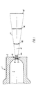
- the liquid-jet nozzle 1 for use in a high-pressure cleaner and shown in the drawing comprises in a manner known per se an inlet chamber 2, the upstream side of which as shown diagrammatically in Figure 2 is adapted to receive liquid under pressure from the liquid pump 3 in a liquid-supply and control unit 4. On the downstream side, the inlet chamber 2 debouches outwardly through a nozzle aperture 5, so that a liquid jet 6 can be ejected as shown in Figure 1.
- the liquid jet 6 progressively spreads outwardly in the shape of a fan, the jet gradually becoming wider and thinner as indicated with the cross-sectional views 6a-6d.
- the liquid jet 6 is quite thin, and if it is directed towards a surface to be cleaned in such a manner, that the liquid jet 6 hits the surface at this distance, a very large cleaning effect will be achieved, comparable to what can be achieved by using a metal scraper of the same width. If the liquid jet 6 is allowed to flow past the location corresponding to the cross-sectional view 6d, it will normally disintegrate to form a great number of small droplets. Trials have shown that the liquid jet 6d as shown exhibits a significantly greater cleaning effect than a jet with a circular cross-sectional shape and having the same mass-flow velocity.
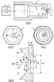
- the nozzle aperture 5 is situated in an end wall 7 in the nozzle 1, and on the upstream side, this end wall 7 comprises an oval recess 8, the longitudinal axis 9 of which extends parallel to the sectional plane of Figure 2, but at right angles to the sectional plane in Figure 1.
- the recess 8 consists of two spherical surfaces 10 connected to each other through a transition surface 11 forming a transition between the two spherical surfaces 10.
- the recess 8 may be produced by means of a ball-shaped milling cutter being moved between the two positions corresponding to the two spherical surfaces 10, so that it produces the transition surface 11 when moving between them.
- the recess 8 is symmetrical, partly about the longitudinal axis 12 for the nozzle aperture 5, partly about its own longitudinal axis 9, and partly about its own transverse axis (not shown) intersecting the longitudinal axis 12 in the nozzle aperture 5.
- the upstream side of the end wall 7 has the shape of a spherical surface 13, the radius 14 of which is the same as the radius in the remainder of the inlet chamber 2.
- a shallow recess 15 is formed on the downstream side of the end wall 7.
- the liquid jet 6 is flattened out in such a manner that its main plane extends at right angles to the longitudinal axis 9 for the recess 8 shown in Figure 4.
- the reason for this is presumably that the spherical surfaces 10, cf. Figure 5, add two oppositely and inwardly directed components to the movement of the liquid flow, so that the liquid jet 6 almost immediately after having left the nozzle aperture 5 has a marked ellipsoidal cross-sectional shape as shown by the cross-sectional view 6a. Since at this location, a certain momentum still remains in the components referred to, the liquid jet 6 will continue flattening out as shown in Figure 1.
- the function of the recess 15 on the downstream side of the end wall 7 is not to influence the liquid flow, but to make it possible to let the nozzle aperture 5 be sufficiently short for achieving the desired effect, at the same time as the end wall 7 may have the requisite mechanical strength, partly to withstand the high internal liquid pressure, partly to withstand the rough treatment, to which high-pressure cleaners are often subjected, and at the same time protect the outlet side of the nozzle aperture 5.
- a number of practical trials with a high-pressure cleaner comprising a liquid-jet nozzle constructed as shown in the drawing have been carried out.
- nozzles have been used, in which the axial length 16 of the nozzle aperture 5 has been between 0.2 and 0.3 times the diameter 17 of the nozzle aperture, and in which the two spherical surfaces 10 have had a radius 18 of between 0.8 and 1.11 times the diameter 17 of the nozzle aperture, said diameter having varied between 1.36 and 1.82 mm, while the centres of curvature 19 for the spherical surfaces 10 have been situated at a distance 20 of between 0.2 and 0.3 times the diameter 17 of the nozzle aperture from the latter's axis 12.
- the spherical surface 13 constituting the upstream side of the end wall 7 has had a radius 14, as mentioned above being the same as the radius of the inlet chamber 2, of between 2 and 3 times the diameter 17 of the nozzle aperture.
- the recess 15 may e.g. have a diameter 21 of between 1 and 1 1/2 times the diameter 17 of the nozzle aperture and a depth 22 of between 1 and 2 times the axial length 16 of the nozzle aperture, possibly a little more, provided that the liquid jet 6 is not influenced.
- the liquid-jet nozzle 1 will normally be made from the same material normally used for such nozzles, e.g. steel, so as to be able to withstand the high internal pressures of the order of magnitude 100-200 bars that may occur in high-pressure cleaners.
Abstract
Description
- The present invention relates to a liquid-jet nozzle of the kind set forth in the preamble of claim 1.
- A liquid-jet nozzle of the kind referred to above is known from the German published specification No. 4,213,226. In this known nozzle, the recess formed in the upstream side of the end wall has a rather complicated shape, partly comprising spherical surfaces, partly "side walls" in continuation of said spherical surfaces, the transitions between the various surfaces being constituted by sharp edges.
- The shape of the recess referred to as known from the above document is the cause of certain disadvantages, both with regard to the flow conditions and with regard to the manufacture of the nozzles. With regard to the flow conditions it is reasonable to believe that the complicated shape of the recess, especially the sharp edges referred to, will create turbulence in the issuing liquid jet and prevent the flattening of the liquid jet from occurring as smoothly as possible. With regard to the manufacture of the nozzle, the complicated shape of the recess makes it impossible to produce it by means of e.g. milling operations, but demands the use of specially designed embossing or stamping tools, that can only be used, if the material of the nozzle lends itself to being shaped by embossing or stamping.
- On this background, it is the object of the present invention to provide a nozzle of the kind referred to initially, that both with regard to flow conditions and manufacture represents an improvement of the known nozzle referred to above, and this object is achieved with a nozzle, according to the present invention additionally exhibiting the features set forth in the characterizing clause of claim 1. Since the recess shaped in accordance with the invention does not comprise complicated surfaces with sharp edges as in the known nozzles, the risk of turbulence is considerably reduced, providing improved possibilities for a smooth flattening of the jet. In the nozzle according to the invention, the recess in the upstream side of the end wall may be formed by a simple milling or grinding process using a milling or grinding tool, respectively, with a rounded end, that may be moved back and forth transversely of the longitudinal direction of the nozzle during the machining operation. Practical trials with the nozzle according to the invention have shown that the liquid jet flattens in such a manner, that at a certain distance from the mouth of the nozzle, it becomes extremely thin, almost to resemble a knife edge - this would hardly be possible with a nozzle, with which there is a risk of turbulence being created.
- Advantageous embodiments of the nozzle according to the invention, the effects of which will be apparent from the following detailed portion of the present description, are set forth in claims 2-4.
- In the following detailed portion of the present specification, the invention will be explained in more detail with reference to the exemplary embodiment of a liquid-jet nozzle according to the invention shown in the drawings, in which
- Figure 1 is a partial sectional view along the line I-I in Figure 2 and illustrates the progressive flattening of the liquid jet,
- Figure 2 is a longitudinal sectional view through the complete liquid-jet nozzle and shows symbolically the connection between the nozzle and the remaining components in the high-pressure cleaner, of which the nozzle is a part,
- Figures 3 and 4 show the nozzle of Figure 2 as viewed from the right and the left, respectively, in Figure 2, and
- Figure 5 at a greatly magnified scale shows a partial sectional view through the nozzle shown in Figure 2, showing the geometrical construction of the nozzle aperture and the region around it.
- The liquid-jet nozzle 1 for use in a high-pressure cleaner and shown in the drawing comprises in a manner known per se an
inlet chamber 2, the upstream side of which as shown diagrammatically in Figure 2 is adapted to receive liquid under pressure from theliquid pump 3 in a liquid-supply andcontrol unit 4. On the downstream side, theinlet chamber 2 debouches outwardly through anozzle aperture 5, so that a liquid jet 6 can be ejected as shown in Figure 1. - As will appear from Figure 1, the liquid jet 6 progressively spreads outwardly in the shape of a fan, the jet gradually becoming wider and thinner as indicated with the cross-sectional views 6a-6d. At the distance, in which the
cross-sectional view 6d appears, the liquid jet 6 is quite thin, and if it is directed towards a surface to be cleaned in such a manner, that the liquid jet 6 hits the surface at this distance, a very large cleaning effect will be achieved, comparable to what can be achieved by using a metal scraper of the same width. If the liquid jet 6 is allowed to flow past the location corresponding to thecross-sectional view 6d, it will normally disintegrate to form a great number of small droplets. Trials have shown that theliquid jet 6d as shown exhibits a significantly greater cleaning effect than a jet with a circular cross-sectional shape and having the same mass-flow velocity. - In order to achieve the spreading of the liquid jet 6 as shown in Figure 1, it is, of course, necessary to adopt special measures for influencing the flow of liquid before it leaves the
nozzle aperture 5. - The
nozzle aperture 5 is situated in anend wall 7 in the nozzle 1, and on the upstream side, thisend wall 7 comprises anoval recess 8, the longitudinal axis 9 of which extends parallel to the sectional plane of Figure 2, but at right angles to the sectional plane in Figure 1. As will appear from Figure 5, therecess 8 consists of twospherical surfaces 10 connected to each other through atransition surface 11 forming a transition between the twospherical surfaces 10. Advantageously, therecess 8 may be produced by means of a ball-shaped milling cutter being moved between the two positions corresponding to the twospherical surfaces 10, so that it produces thetransition surface 11 when moving between them. - The
recess 8 is symmetrical, partly about thelongitudinal axis 12 for thenozzle aperture 5, partly about its own longitudinal axis 9, and partly about its own transverse axis (not shown) intersecting thelongitudinal axis 12 in thenozzle aperture 5. - In the exemplary embodiment shown, the upstream side of the
end wall 7 has the shape of aspherical surface 13, theradius 14 of which is the same as the radius in the remainder of theinlet chamber 2. - A
shallow recess 15 is formed on the downstream side of theend wall 7. - Referring to Figures 1, 2 and 4, it should be noted that the liquid jet 6 is flattened out in such a manner that its main plane extends at right angles to the longitudinal axis 9 for the
recess 8 shown in Figure 4. The reason for this is presumably that thespherical surfaces 10, cf. Figure 5, add two oppositely and inwardly directed components to the movement of the liquid flow, so that the liquid jet 6 almost immediately after having left thenozzle aperture 5 has a marked ellipsoidal cross-sectional shape as shown by the cross-sectional view 6a. Since at this location, a certain momentum still remains in the components referred to, the liquid jet 6 will continue flattening out as shown in Figure 1. - The function of the
recess 15 on the downstream side of theend wall 7 is not to influence the liquid flow, but to make it possible to let thenozzle aperture 5 be sufficiently short for achieving the desired effect, at the same time as theend wall 7 may have the requisite mechanical strength, partly to withstand the high internal liquid pressure, partly to withstand the rough treatment, to which high-pressure cleaners are often subjected, and at the same time protect the outlet side of thenozzle aperture 5. - A number of practical trials with a high-pressure cleaner comprising a liquid-jet nozzle constructed as shown in the drawing have been carried out. During these trials, nozzles have been used, in which the
axial length 16 of thenozzle aperture 5 has been between 0.2 and 0.3 times thediameter 17 of the nozzle aperture, and in which the twospherical surfaces 10 have had aradius 18 of between 0.8 and 1.11 times thediameter 17 of the nozzle aperture, said diameter having varied between 1.36 and 1.82 mm, while the centres ofcurvature 19 for thespherical surfaces 10 have been situated at adistance 20 of between 0.2 and 0.3 times thediameter 17 of the nozzle aperture from the latter'saxis 12. - During the trials the
spherical surface 13 constituting the upstream side of theend wall 7 has had aradius 14, as mentioned above being the same as the radius of theinlet chamber 2, of between 2 and 3 times thediameter 17 of the nozzle aperture. - The
recess 15 may e.g. have adiameter 21 of between 1 and 1 1/2 times thediameter 17 of the nozzle aperture and adepth 22 of between 1 and 2 times theaxial length 16 of the nozzle aperture, possibly a little more, provided that the liquid jet 6 is not influenced. - The liquid-jet nozzle 1 will normally be made from the same material normally used for such nozzles, e.g. steel, so as to be able to withstand the high internal pressures of the order of magnitude 100-200 bars that may occur in high-pressure cleaners.
-
- 1
- liquid-jet nozzle
- 2
- inlet chamber
- 3
- liquid pump
- 4
- liquid-supply and control unit
- 5
- nozzle aperture
- 6
- liquid jet
- 6a-d
- cross-sectional view
- 7
- end wall
- 8
- recess
- 9
- longitudinal axis
- 10
- spherical surface
- 11
- transition surface
- 12
- longitudinal axis
- 13
- spherical surface
- 14
- radius
- 15
- recess
- 16
- length
- 17
- diameter
- 18
- radius
- 19
- centre of curvature
- 20
- distance
- 21
- diameter
- 22
- depth
Claims (4)
- Liquid-jet nozzle (1) for ejecting a progressively flattening jet (6) of cleaning liquid at high pressure, said liquid-jet nozzle being of the kind comprisinga) a nozzle aperture (5) extending through an end wall (7) extending transversely to the main direction of flow of the liquid jet (6),b) upstream of the nozzle aperture (5) and opening into the latter an inlet chamber (2) connected to the outlet of the liquid pump (3) of a high-pressure cleaner, andc) in the upstream side of the end wall (7), an elongate recess (8), the longitudinal central axis (9) of which intersects the central axis (12) of the nozzle aperture (5) at right angles,characterized ind) that the recess (8) is oval and consists of ipsilaterally concavely curved surfaces extending smoothly into each other so as to form a continuous surface without sudden transitions or sharp edges.
- Nozzle according to claim 1, characterized in that the width of the recess (8) is more than one fifth of and less than five times the diameter (17) of the nozzle aperture (5).
- Nozzle according to claim 2, characterized ina) that the length (16) of the nozzle aperture (5) is between 0.2 and 0.3 times the diameter (17) of the nozzle aperture (5), andb) that the recess (8) consists of two spherical surfaces (10) each having a radius (18) of between 0.8 and 1.11 times the diameter (17) of the nozzle aperture (5) and with the centres of curvature (19) situated at a distance (20) of between 0.2 and 0.3 times the diameter (17) of the nozzle aperture (5) from the latter's axis (12), as well as a transition surface (11) situated between the two spherical surfaces (10) and forming a smooth transition between them.
- Nozzle according to claim 3 and in which the upstream side of the end walls (7) constitutes a spherical surface (13) with the same radius (14) as that of the inlet chamber (2), characterized in that said radius is between two and three times the diameter (17) of the nozzle aperture (5).
Applications Claiming Priority (2)
| Application Number | Priority Date | Filing Date | Title |
|---|---|---|---|
| DK132593A DK171017B1 (en) | 1993-11-25 | 1993-11-25 | Flat jet nozzle, especially for a high pressure cleaner |
| DK1325/93 | 1993-11-25 |
Publications (2)
| Publication Number | Publication Date |
|---|---|
| EP0655281A1 EP0655281A1 (en) | 1995-05-31 |
| EP0655281B1 true EP0655281B1 (en) | 1996-01-17 |
Family
ID=8103600
Family Applications (1)
| Application Number | Title | Priority Date | Filing Date |
|---|---|---|---|
| EP94117416A Expired - Lifetime EP0655281B1 (en) | 1993-11-25 | 1994-11-04 | Flat-jet nozzle, especially for use in a high-pressure cleaner |
Country Status (4)
| Country | Link |
|---|---|
| EP (1) | EP0655281B1 (en) |
| AT (1) | ATE133091T1 (en) |
| DE (2) | DE69400060T2 (en) |
| DK (1) | DK171017B1 (en) |
Families Citing this family (7)
| Publication number | Priority date | Publication date | Assignee | Title |
|---|---|---|---|---|
| JP3494327B2 (en) * | 1995-10-03 | 2004-02-09 | 株式会社共立合金製作所 | Descaler nozzle |
| DE19541174C2 (en) * | 1995-11-04 | 1998-11-26 | Spraying Systems Deutschland G | High performance jet nozzle |
| DE19700054C1 (en) * | 1997-01-02 | 1998-04-30 | Hartmann Kulba Bauchemie Gmbh | Jet nozzle for equipment used to remove coatings on surfaces |
| US5931392A (en) * | 1997-03-07 | 1999-08-03 | Adams; Robert J. | High-pressure cleaning spray nozzle |
| DE19918257A1 (en) * | 1999-04-22 | 2000-11-23 | Lechler Gmbh & Co Kg | High pressure spray nozzle |
| PL2931434T3 (en) | 2012-12-14 | 2017-04-28 | Alfred Kärcher Gmbh & Co. Kg | Fan nozzle |
| JP2022128918A (en) * | 2021-02-24 | 2022-09-05 | セイコーエプソン株式会社 | Liquid injection device for skin cleaning |
Family Cites Families (3)
| Publication number | Priority date | Publication date | Assignee | Title |
|---|---|---|---|---|
| US4097000A (en) * | 1975-07-07 | 1978-06-27 | Derr Bernard A | Spray nozzle |
| DE4213226C2 (en) * | 1992-04-23 | 1996-08-22 | Lechler Gmbh & Co Kg | Flat jet nozzle, in particular high pressure jet nozzle |
| DE4303762A1 (en) * | 1993-02-09 | 1994-08-11 | Kaercher Gmbh & Co Alfred | Flat jet nozzle for a high pressure cleaning device |
-
1993
- 1993-11-25 DK DK132593A patent/DK171017B1/en not_active IP Right Cessation
-
1994
- 1994-11-04 AT AT94117416T patent/ATE133091T1/en active
- 1994-11-04 EP EP94117416A patent/EP0655281B1/en not_active Expired - Lifetime
- 1994-11-04 DE DE69400060T patent/DE69400060T2/en not_active Expired - Lifetime
- 1994-11-07 DE DE9417806U patent/DE9417806U1/en not_active Expired - Lifetime
Also Published As
| Publication number | Publication date |
|---|---|
| ATE133091T1 (en) | 1996-02-15 |
| DE9417806U1 (en) | 1994-12-22 |
| DE69400060T2 (en) | 1996-07-04 |
| DK171017B1 (en) | 1996-04-22 |
| DK132593A (en) | 1995-05-26 |
| DK132593D0 (en) | 1993-11-25 |
| EP0655281A1 (en) | 1995-05-31 |
| DE69400060D1 (en) | 1996-02-29 |
Similar Documents
| Publication | Publication Date | Title |
|---|---|---|
| EP0792692B1 (en) | Scale removing nozzle | |
| US4798339A (en) | Submerged jet injection nozzle | |
| EP0181911B1 (en) | Movable hydrodynamic nozzle for pressurized water cleaning of water, discharge and surface water pipes | |
| CA2922030C (en) | Flat jet nozzle, and use of a flat jet nozzle | |
| KR920007952B1 (en) | Descaling nozzle | |
| JP2637626B2 (en) | Flat jet nozzle for high pressure cleaning equipment | |
| EP0655281B1 (en) | Flat-jet nozzle, especially for use in a high-pressure cleaner | |
| EP0862950B1 (en) | High-pressure cleaning spray nozzle | |
| US20190240632A1 (en) | Fertilizer production system | |
| JPH08173861A (en) | Nozzle with improved air cap for spray gun | |
| EP3539721B1 (en) | Multi-jet abrasive head | |
| JPH03238060A (en) | Airless painting spray nozzle | |
| US2341859A (en) | Nozzle | |
| JPH08141912A (en) | Cutting water jet nozzle | |
| EP1275760A3 (en) | Weft conveying nozzle in an air jet loom | |
| JP4504641B2 (en) | Spray nozzle and spraying method using the same | |
| JPH1034024A (en) | Spray nozzle | |
| CN112691799A (en) | High-pressure fan-shaped nozzle applied to washing and sweeping vehicle | |
| JPH0798168B2 (en) | Fan-shaped spray nozzle and manufacturing method thereof | |
| JPH07300786A (en) | Nozzle for cleaning |
Legal Events
| Date | Code | Title | Description |
|---|---|---|---|
| PUAI | Public reference made under article 153(3) epc to a published international application that has entered the european phase |
Free format text: ORIGINAL CODE: 0009012 |
|
| 17P | Request for examination filed |
Effective date: 19941115 |
|
| AK | Designated contracting states |
Kind code of ref document: A1 Designated state(s): AT BE CH DE DK ES FR GB GR IE IT LI LU MC NL PT SE |
|
| 17Q | First examination report despatched |
Effective date: 19950619 |
|
| GRAA | (expected) grant |
Free format text: ORIGINAL CODE: 0009210 |
|
| RAP1 | Party data changed (applicant data changed or rights of an application transferred) |
Owner name: KEW INDUSTRI A/S |
|
| AK | Designated contracting states |
Kind code of ref document: B1 Designated state(s): AT BE CH DE DK ES FR GB GR IE IT LI LU MC NL PT SE |
|
| AX | Request for extension of the european patent |
Free format text: SI PAYMENT 941104 |
|
| PG25 | Lapsed in a contracting state [announced via postgrant information from national office to epo] |
Ref country code: NL Free format text: LAPSE BECAUSE OF FAILURE TO SUBMIT A TRANSLATION OF THE DESCRIPTION OR TO PAY THE FEE WITHIN THE PRESCRIBED TIME-LIMIT Effective date: 19960117 Ref country code: LI Effective date: 19960117 Ref country code: GR Free format text: LAPSE BECAUSE OF FAILURE TO SUBMIT A TRANSLATION OF THE DESCRIPTION OR TO PAY THE FEE WITHIN THE PRESCRIBED TIME-LIMIT Effective date: 19960117 Ref country code: FR Effective date: 19960117 Ref country code: ES Free format text: THE PATENT HAS BEEN ANNULLED BY A DECISION OF A NATIONAL AUTHORITY Effective date: 19960117 Ref country code: DK Effective date: 19960117 Ref country code: CH Effective date: 19960117 Ref country code: BE Effective date: 19960117 Ref country code: AT Effective date: 19960117 |
|
| RAX | Requested extension states of the european patent have changed |
Free format text: SI PAYMENT 941104 |
|
| REF | Corresponds to: |
Ref document number: 133091 Country of ref document: AT Date of ref document: 19960215 Kind code of ref document: T |
|
| REG | Reference to a national code |
Ref country code: IE Ref legal event code: FG4D Free format text: 66978 |
|
| ITF | It: translation for a ep patent filed |
Owner name: ING. A. GIAMBROCONO & C. S.R.L. |
|
| REF | Corresponds to: |
Ref document number: 69400060 Country of ref document: DE Date of ref document: 19960229 |
|
| PG25 | Lapsed in a contracting state [announced via postgrant information from national office to epo] |
Ref country code: SE Effective date: 19960417 Ref country code: PT Effective date: 19960417 |
|
| EN | Fr: translation not filed | ||
| NLV1 | Nl: lapsed or annulled due to failure to fulfill the requirements of art. 29p and 29m of the patents act | ||
| REG | Reference to a national code |
Ref country code: CH Ref legal event code: PL |
|
| PG25 | Lapsed in a contracting state [announced via postgrant information from national office to epo] |
Ref country code: IE Free format text: LAPSE BECAUSE OF NON-PAYMENT OF DUE FEES Effective date: 19961104 |
|
| PLBE | No opposition filed within time limit |
Free format text: ORIGINAL CODE: 0009261 |
|
| STAA | Information on the status of an ep patent application or granted ep patent |
Free format text: STATUS: NO OPPOSITION FILED WITHIN TIME LIMIT |
|
| PG25 | Lapsed in a contracting state [announced via postgrant information from national office to epo] |
Ref country code: LU Free format text: LAPSE BECAUSE OF NON-PAYMENT OF DUE FEES Effective date: 19961130 |
|
| 26N | No opposition filed | ||
| PG25 | Lapsed in a contracting state [announced via postgrant information from national office to epo] |
Ref country code: MC Effective date: 19970531 |
|
| PG25 | Lapsed in a contracting state [announced via postgrant information from national office to epo] |
Ref country code: GB Free format text: LAPSE BECAUSE OF NON-PAYMENT OF DUE FEES Effective date: 19981104 |
|
| GBPC | Gb: european patent ceased through non-payment of renewal fee |
Effective date: 19981104 |
|
| PG25 | Lapsed in a contracting state [announced via postgrant information from national office to epo] |
Ref country code: IT Free format text: LAPSE BECAUSE OF NON-PAYMENT OF DUE FEES;WARNING: LAPSES OF ITALIAN PATENTS WITH EFFECTIVE DATE BEFORE 2007 MAY HAVE OCCURRED AT ANY TIME BEFORE 2007. THE CORRECT EFFECTIVE DATE MAY BE DIFFERENT FROM THE ONE RECORDED. Effective date: 20051104 |
|
| PGFP | Annual fee paid to national office [announced via postgrant information from national office to epo] |
Ref country code: DE Payment date: 20131122 Year of fee payment: 20 |
|
| REG | Reference to a national code |
Ref country code: DE Ref legal event code: R071 Ref document number: 69400060 Country of ref document: DE |
|
| REG | Reference to a national code |
Ref country code: DE Ref legal event code: R071 Ref document number: 69400060 Country of ref document: DE |