EP0654810A1 - Tube image couleur muni d'une structure de renforcement en forme de boîte pour un masque - Google Patents
Tube image couleur muni d'une structure de renforcement en forme de boîte pour un masque Download PDFInfo
- Publication number
- EP0654810A1 EP0654810A1 EP94117907A EP94117907A EP0654810A1 EP 0654810 A1 EP0654810 A1 EP 0654810A1 EP 94117907 A EP94117907 A EP 94117907A EP 94117907 A EP94117907 A EP 94117907A EP 0654810 A1 EP0654810 A1 EP 0654810A1
- Authority
- EP
- European Patent Office
- Prior art keywords
- mask
- shadow mask
- reinforcing structure
- skirt
- panel
- Prior art date
- Legal status (The legal status is an assumption and is not a legal conclusion. Google has not performed a legal analysis and makes no representation as to the accuracy of the status listed.)
- Withdrawn
Links
Images

Classifications
-
- H—ELECTRICITY
- H01—ELECTRIC ELEMENTS
- H01J—ELECTRIC DISCHARGE TUBES OR DISCHARGE LAMPS
- H01J29/00—Details of cathode-ray tubes or of electron-beam tubes of the types covered by group H01J31/00
- H01J29/02—Electrodes; Screens; Mounting, supporting, spacing or insulating thereof
- H01J29/06—Screens for shielding; Masks interposed in the electron stream
- H01J29/07—Shadow masks for colour television tubes
- H01J29/073—Mounting arrangements associated with shadow masks
-
- H—ELECTRICITY
- H01—ELECTRIC ELEMENTS
- H01J—ELECTRIC DISCHARGE TUBES OR DISCHARGE LAMPS
- H01J2229/00—Details of cathode ray tubes or electron beam tubes
- H01J2229/07—Shadow masks
- H01J2229/0722—Frame
-
- H—ELECTRICITY
- H01—ELECTRIC ELEMENTS
- H01J—ELECTRIC DISCHARGE TUBES OR DISCHARGE LAMPS
- H01J2229/00—Details of cathode ray tubes or electron beam tubes
- H01J2229/07—Shadow masks
- H01J2229/0727—Aperture plate
- H01J2229/0766—Details of skirt or border
- H01J2229/0772—Apertures, cut-outs, depressions, or the like
Definitions
- This invention relates to color picture tubes of the type having shadow masks that are suspended in relation to cathodoluminescent screens, and particularly to an improved lighter-weight shadow mask.
- color picture tubes use steel frames to support shadow masks within faceplate panels of the tubes.
- One type of frame is made from a continuous piece of L-shaped steel that is bent and welded to itself at its ends.
- Another type of frame is formed by pressing a flat steel sheet into the shape of the frame.
- these types of frames are made from materials that are about 1.00 mm (0.039 inch) thick and weigh about 1.63 kg (3.6 lbs).
- Other frames can be as thick as 1.51 mm (0.062 inch) and are proportionately heavier.
- the frames are usually rectangularly shaped and supported within faceplate panels by either three or four springs that are attached to the sides of the frames; alternatively, the frames may be supported at their four corners. Embodiments for achieving such corner support are shown in U.S. Patent 4,723,088, issued to Sone et al. on February 2, 1988, and U.S. Patent 4,728,853, issued to Sone et al. on March 1, 1988.
- the present invention provides a shadow mask that does not utilize a conventional frame.
- An improved color picture tube in accordance with the present invention includes an evacuated envelope having a rectangular faceplate panel.
- the panel includes a viewing screen on an inner surface thereof and a shadow mask mounted therein.
- the shadow mask includes an apertured contoured portion and a reinforcing structure peripherally attached to the apertured portion.
- the reinforcing structure and a portion of the mask form a box-like enclosure around the periphery of the mask.
- the reinforcing structure is constructed of a material that has approximately the same thickness as does the shadow mask material.
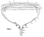
- FIGURE 1 shows a rectangular color picture tube 8 having a glass envelope 10, comprising a rectangular faceplate panel 12 and a tubular neck 14 connected by a rectangular funnel 16.
- the panel 12 comprises a viewing faceplate 18 and a peripheral flange or sidewall 20, which is sealed to the funnel 16.
- a mosaic three-color phosphor screen 22 is located on the inner surface of the faceplate 18.
- the screen preferably is a line screen, with vertically extending parallel phosphor lines. Alternatively, the screen may be a dot screen.
- a multiapertured color selection electrode or shadow mask 24 is removably mounted in predetermined spaced relation to the screen 22.
- An electron gun 25 is centrally mounted within the neck 14, to generate and direct three electron beams along convergent paths through the mask 24 to the screen 22.
- the tube of FIGURE 1 is designed to be used with an external magnetic deflection yoke 28 located in the vicinity of the funnel-to-neck junction.
- the yoke 28 subjects the three electron beams to magnetic fields which cause the beams to scan horizontally and vertically in a rectangular raster over the screen 22.
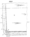
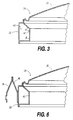
- the shadow mask 24, shown in greater detail in FIGURES 2 and 3, includes an apertured contoured portion 26 and a peripheral skirt 30 that surrounds the apertured portion 26.
- the shadow mask is mounted within the faceplate panel 12 by four support means 34 positioned at the four corners of the shadow mask.
- One such support means 34 is shown in FIGURE 2.
- Each support means 34 includes a stud 36 embedded in the panel sidewall 20, a spring 38 which engages the stud, and a bracket 40 that is attached to the skirt 30 of the shadow mask.
- the mask 24 may be suspended by support means located along the sides of the mask.
- the shadow mask 24 does not use a thick peripheral reinforcing frame, as taught by the prior art. Instead, the skirt 30 of the shadow mask 24 is reinforced by use of a generally C-shaped reinforcing structure 42 that is peripherally attached to the inside surface of the skirt 30.
- the C-shape is formed by an obtuse angle ⁇ and a right angle ⁇ in cross-section in the structure 42.
- the reinforcing structure 42 and the skirt 30 form a rigid box-like enclosure 43 around the periphery of the mask, with the reinforcing structure forming three sides of the enclosure.
- the material of the reinforcing structure 42 has approximately the same thickness as does the mask material, e.g., 0.229 mm (0.009 inch).
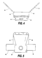
- the spring 38 and bracket 40 are shown in greater detail in FIGURES 4, 5 and 6.
- One end of the spring 38 is welded to the bracket 40, and the other end of the spring includes an aperture 44 which engages the stud 36.
- the bracket 40 includes a center section 46, to which the spring 38 is welded, and two legs 48 and 50.
- the legs 48 and 50 extend along adjacent sides of the mask and are welded to the outside surface of the mask skirt 30.
- FIGURE 7 a minor modification to the preferred embodiment is shown in FIGURE 7.
- a mask 60 is shown having a box-like enclosure 61 formed by a C-shaped reinforcing structure 62 having two right angles in cross-section.
- an iron-nickel mask 70 has a U-shaped skirt 72 which forms a side of a box-like enclosure 73.
- the remainder of the enclosure 73 is formed by a C-shaped structure 74 that is attached to the outside surface of the skirt 72 at peripheral points 76 and to the bottom of the U-shape of the skirt at peripheral points 78.
- a flange 79 of the structure 74 extends toward the center of the mask, to serve as an electron beam overscan shield.
- a mask 80 shown in FIGURE 9, is similar to the embodiment of FIGURE 8, in that it has a U-shaped skirt 82 and a C-shaped structure 84 forming a box-like enclosure 86, except that the structure 84 touches the outside portion of the U of the skirt 82.
- a mask and mask support means constructed in accordance with the present invention uses a minimum amount of material and is lighter than one which uses a frame. This results in cost reduction, better thermal performance and reduced warpage during long-term operation.
- the thinner material of the reinforcing structure is easier to machine, and the completed mask assembly and support are still sufficiently sturdy to withstand mechanical shocks and vibrations.
Landscapes
- Electrodes For Cathode-Ray Tubes (AREA)
- Video Image Reproduction Devices For Color Tv Systems (AREA)
Applications Claiming Priority (2)
| Application Number | Priority Date | Filing Date | Title |
|---|---|---|---|
| ITMI932461 | 1993-11-19 | ||
| IT93MI002461A IT1265204B1 (it) | 1993-11-19 | 1993-11-19 | Tubo per la riproduzione di immagini a colori dotato di una maschera d'ombra perfezionata |
Publications (1)
| Publication Number | Publication Date |
|---|---|
| EP0654810A1 true EP0654810A1 (fr) | 1995-05-24 |
Family
ID=11367233
Family Applications (1)
| Application Number | Title | Priority Date | Filing Date |
|---|---|---|---|
| EP94117907A Withdrawn EP0654810A1 (fr) | 1993-11-19 | 1994-11-12 | Tube image couleur muni d'une structure de renforcement en forme de boîte pour un masque |
Country Status (6)
| Country | Link |
|---|---|
| EP (1) | EP0654810A1 (fr) |
| JP (1) | JPH07192649A (fr) |
| KR (1) | KR950015501A (fr) |
| CN (1) | CN1111392A (fr) |
| IT (1) | IT1265204B1 (fr) |
| TW (1) | TW301757B (fr) |
Cited By (2)
| Publication number | Priority date | Publication date | Assignee | Title |
|---|---|---|---|---|
| EP0774771A1 (fr) * | 1995-11-15 | 1997-05-21 | Thomson Consumer Electronics, Inc. | Tube d'image en couleurs muni d'un masque tendu et d'une structure de support souple |
| WO2006054014A1 (fr) * | 2004-11-18 | 2006-05-26 | Thomson Licensing | Ensemble cadre/masque pour tube a rayons cathodiques |
Families Citing this family (2)
| Publication number | Priority date | Publication date | Assignee | Title |
|---|---|---|---|---|
| US6710527B2 (en) | 2000-08-04 | 2004-03-23 | Matsushita Electric Industrial Co., Ltd. | Cathode ray tube with slit in dead space of shadow mask |
| KR20020061950A (ko) * | 2001-01-19 | 2002-07-25 | 엘지전자주식회사 | 칼라 음극선관 |
Citations (4)
| Publication number | Priority date | Publication date | Assignee | Title |
|---|---|---|---|---|
| JPS5688239A (en) * | 1979-12-19 | 1981-07-17 | Hitachi Ltd | Shadow mask assembly |
| US4700105A (en) * | 1985-09-30 | 1987-10-13 | Mitsubishi Denki Kabushiki Kaisha | Shadow mask mount for color picture tube |
| US5021707A (en) * | 1989-11-17 | 1991-06-04 | Rca Licensing Corporation | Color picture tube having shadow mask with improved support |
| US5072151A (en) * | 1991-01-14 | 1991-12-10 | Videocolor S.P.A. | Color picture tube having improved shadow mask frame |
-
1993
- 1993-11-19 IT IT93MI002461A patent/IT1265204B1/it active IP Right Grant
-
1994
- 1994-09-14 TW TW083108480A patent/TW301757B/zh active
- 1994-11-12 EP EP94117907A patent/EP0654810A1/fr not_active Withdrawn
- 1994-11-16 KR KR1019940030002A patent/KR950015501A/ko not_active Application Discontinuation
- 1994-11-18 CN CN94118408A patent/CN1111392A/zh active Pending
- 1994-11-18 JP JP6321784A patent/JPH07192649A/ja active Pending
Patent Citations (4)
| Publication number | Priority date | Publication date | Assignee | Title |
|---|---|---|---|---|
| JPS5688239A (en) * | 1979-12-19 | 1981-07-17 | Hitachi Ltd | Shadow mask assembly |
| US4700105A (en) * | 1985-09-30 | 1987-10-13 | Mitsubishi Denki Kabushiki Kaisha | Shadow mask mount for color picture tube |
| US5021707A (en) * | 1989-11-17 | 1991-06-04 | Rca Licensing Corporation | Color picture tube having shadow mask with improved support |
| US5072151A (en) * | 1991-01-14 | 1991-12-10 | Videocolor S.P.A. | Color picture tube having improved shadow mask frame |
Non-Patent Citations (1)
| Title |
|---|
| PATENT ABSTRACTS OF JAPAN vol. 5, no. 159 (E - 77)<831> 14 October 1981 (1981-10-14) * |
Cited By (2)
| Publication number | Priority date | Publication date | Assignee | Title |
|---|---|---|---|---|
| EP0774771A1 (fr) * | 1995-11-15 | 1997-05-21 | Thomson Consumer Electronics, Inc. | Tube d'image en couleurs muni d'un masque tendu et d'une structure de support souple |
| WO2006054014A1 (fr) * | 2004-11-18 | 2006-05-26 | Thomson Licensing | Ensemble cadre/masque pour tube a rayons cathodiques |
Also Published As
| Publication number | Publication date |
|---|---|
| TW301757B (fr) | 1997-04-01 |
| ITMI932461A1 (it) | 1995-05-19 |
| KR950015501A (ko) | 1995-06-17 |
| JPH07192649A (ja) | 1995-07-28 |
| IT1265204B1 (it) | 1996-10-31 |
| CN1111392A (zh) | 1995-11-08 |
| ITMI932461A0 (it) | 1993-11-19 |
Similar Documents
| Publication | Publication Date | Title |
|---|---|---|
| US5072151A (en) | Color picture tube having improved shadow mask frame | |
| KR940000301B1 (ko) | 샤도우 마스크의 프레임 어셈블리 지지부를 가진 칼라 화상 튜브 | |
| EP0654811A1 (fr) | Tube image couleur muni d'une structure masque-cadre en forme de boîte | |
| EP0654810A1 (fr) | Tube image couleur muni d'une structure de renforcement en forme de boîte pour un masque | |
| US5063325A (en) | Color picture tube having improved shadow mask-frame assembly support | |
| CA2029534C (fr) | Tube image couleur a support de masque perfore ameliore | |
| US5689150A (en) | Color picture tube having improved shadow mask frame | |
| CA2039822C (fr) | Ecran cathodique avec dalle de verre presentant un rapport hauteur/largeur 16 x 9 ameliore | |
| EP1089311A2 (fr) | Tube cathodique couleur | |
| CA2049671C (fr) | Tube image couleur a cadre de masque perfore ameliore | |
| US6731055B2 (en) | Color picture tube having a low expansion tension mask attached to a higher expansion frame | |
| US5233266A (en) | Color picture tube having improved shadow mask-frame assembly support | |
| CA2038225C (fr) | Tube image couleur a support de coin ameliore pour masque perfore | |
| US6411024B1 (en) | Color picture tube | |
| JPH10261369A (ja) | 内部磁気シールド構体およびそれを備えた陰極線管 | |
| KR950012699B1 (ko) | 개량된 섀도우 마스크-프레임 어셈블리를 갖는 칼라 화상관 | |
| CA1292500C (fr) | Tube image couleur a ensemble cadre-masque perfore ameliore | |
| US6737795B2 (en) | Color display tube with improved color selection electrode | |
| WO2003044822A1 (fr) | Ensemble cadre de masque pour tube cathodique |
Legal Events
| Date | Code | Title | Description |
|---|---|---|---|
| PUAI | Public reference made under article 153(3) epc to a published international application that has entered the european phase |
Free format text: ORIGINAL CODE: 0009012 |
|
| AK | Designated contracting states |
Kind code of ref document: A1 Designated state(s): DE FR |
|
| 17P | Request for examination filed |
Effective date: 19951028 |
|
| STAA | Information on the status of an ep patent application or granted ep patent |
Free format text: STATUS: THE APPLICATION HAS BEEN WITHDRAWN |
|
| 18W | Application withdrawn |
Withdrawal date: 19960112 |