EP0654375A1 - Projecteur de véhicule notamment automobile - Google Patents
Projecteur de véhicule notamment automobile Download PDFInfo
- Publication number
- EP0654375A1 EP0654375A1 EP94402683A EP94402683A EP0654375A1 EP 0654375 A1 EP0654375 A1 EP 0654375A1 EP 94402683 A EP94402683 A EP 94402683A EP 94402683 A EP94402683 A EP 94402683A EP 0654375 A1 EP0654375 A1 EP 0654375A1
- Authority
- EP
- European Patent Office
- Prior art keywords
- corrector
- housing
- reflector
- reflectors
- source
- Prior art date
- Legal status (The legal status is an assumption and is not a legal conclusion. Google has not performed a legal analysis and makes no representation as to the accuracy of the status listed.)
- Granted
Links
Images
Classifications
-
- B—PERFORMING OPERATIONS; TRANSPORTING
- B60—VEHICLES IN GENERAL
- B60Q—ARRANGEMENT OF SIGNALLING OR LIGHTING DEVICES, THE MOUNTING OR SUPPORTING THEREOF OR CIRCUITS THEREFOR, FOR VEHICLES IN GENERAL
- B60Q1/00—Arrangement of optical signalling or lighting devices, the mounting or supporting thereof or circuits therefor
- B60Q1/02—Arrangement of optical signalling or lighting devices, the mounting or supporting thereof or circuits therefor the devices being primarily intended to illuminate the way ahead or to illuminate other areas of way or environments
- B60Q1/04—Arrangement of optical signalling or lighting devices, the mounting or supporting thereof or circuits therefor the devices being primarily intended to illuminate the way ahead or to illuminate other areas of way or environments the devices being headlights
- B60Q1/06—Arrangement of optical signalling or lighting devices, the mounting or supporting thereof or circuits therefor the devices being primarily intended to illuminate the way ahead or to illuminate other areas of way or environments the devices being headlights adjustable, e.g. remotely-controlled from inside vehicle
- B60Q1/076—Arrangement of optical signalling or lighting devices, the mounting or supporting thereof or circuits therefor the devices being primarily intended to illuminate the way ahead or to illuminate other areas of way or environments the devices being headlights adjustable, e.g. remotely-controlled from inside vehicle by electrical means including means to transmit the movements, e.g. shafts or joints
-
- B—PERFORMING OPERATIONS; TRANSPORTING
- B60—VEHICLES IN GENERAL
- B60Q—ARRANGEMENT OF SIGNALLING OR LIGHTING DEVICES, THE MOUNTING OR SUPPORTING THEREOF OR CIRCUITS THEREFOR, FOR VEHICLES IN GENERAL
- B60Q1/00—Arrangement of optical signalling or lighting devices, the mounting or supporting thereof or circuits therefor
- B60Q1/0064—Arrangement of optical signalling or lighting devices, the mounting or supporting thereof or circuits therefor with provision for maintenance, e.g. changing the light bulb
- B60Q1/007—Arrangement of optical signalling or lighting devices, the mounting or supporting thereof or circuits therefor with provision for maintenance, e.g. changing the light bulb via a removable cap
-
- B—PERFORMING OPERATIONS; TRANSPORTING
- B60—VEHICLES IN GENERAL
- B60Q—ARRANGEMENT OF SIGNALLING OR LIGHTING DEVICES, THE MOUNTING OR SUPPORTING THEREOF OR CIRCUITS THEREFOR, FOR VEHICLES IN GENERAL
- B60Q1/00—Arrangement of optical signalling or lighting devices, the mounting or supporting thereof or circuits therefor
- B60Q1/0088—Details of electrical connections
-
- F—MECHANICAL ENGINEERING; LIGHTING; HEATING; WEAPONS; BLASTING
- F21—LIGHTING
- F21S—NON-PORTABLE LIGHTING DEVICES; SYSTEMS THEREOF; VEHICLE LIGHTING DEVICES SPECIALLY ADAPTED FOR VEHICLE EXTERIORS
- F21S41/00—Illuminating devices specially adapted for vehicle exteriors, e.g. headlamps
- F21S41/10—Illuminating devices specially adapted for vehicle exteriors, e.g. headlamps characterised by the light source
- F21S41/19—Attachment of light sources or lamp holders
- F21S41/192—Details of lamp holders, terminals or connectors
-
- B—PERFORMING OPERATIONS; TRANSPORTING
- B60—VEHICLES IN GENERAL
- B60Q—ARRANGEMENT OF SIGNALLING OR LIGHTING DEVICES, THE MOUNTING OR SUPPORTING THEREOF OR CIRCUITS THEREFOR, FOR VEHICLES IN GENERAL
- B60Q2200/00—Special features or arrangements of vehicle headlamps
- B60Q2200/30—Special arrangements for adjusting headlamps, e.g. means for transmitting the movements for adjusting the lamps
- B60Q2200/36—Conjoint adjustments, i.e. a mechanical link allows conjoint adjustment of several units
Definitions
- the present invention relates to the field of vehicle equipment. It relates more particularly to a vehicle headlight, in particular an automobile.
- the invention relates more precisely to a headlight comprising an electrically controlled corrector, of a type known per se.
- an electric corrector is a device provided with a small electric motor able to move in translation a threaded rod whose free end carries a ball joint which is housed in a cup secured to the reflector.
- the reflector is articulated, and the displacement of the rod makes it possible to slightly pivot the reflector around its axis of articulation in order to modify its spatial orientation.
- the corrector is mounted outside the projector housing and is connected to a separate connector, independent of the connectors which supply the lamp or lamps which are (are) inside the housing.
- the corrector Due to its installation outside the headlight housing, the corrector constitutes an element which on the one hand occupies a non-negligible place, and on the other hand is exposed to the external environment, in particular to humidity, to dust. , liquid splashes, etc.
- the mounting and electrical connection of the corrector are operations which are independently of the lamp connection operation, so that the overall time required for assembly is relatively high.
- the object of the invention is to propose a headlamp which allows both simple and rapid electrical connections of the corrector and of the lamps, and a simple and rapid mounting of the corrector.
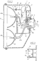
- the projector 1 shown in Figure 1 comprises a housing 2 inside which are mounted two reflectors 4a and 4b, this housing being closed, in the usual manner, by a cover of transparent material 3 having suitable optical properties, commonly called glass .
- One 4b of the two reflectors could consist of a simple signaling device.
- the glass 3 is suitably fixed to the housing 2, for example by clipping and / or using screws.
- Appropriate support members 8, 80 ensure the attachment and retention of the two reflectors 4a, 4b in their correct position inside the housing.
- the light sources (electric lamps) of the reflectors 4a, respectively 4b have been designated by the references 40a and 40b. These lamps are each supplied by a pair of cables 41a, 41b respectively.
- This projector is equipped with an electrical correcting device 6 which makes it possible to modify the orientation of one of the two reflectors, in this case the reflector 4a.
- the section plane of FIG. 1 is a vertical plane
- the reflectors 4a and 4b are superimposed, and the corrector 6 is adapted to modify the inclination of the reflector 4a in the vertical direction (from top to bottom or from bottom up).
- This adjustment is made by displacement of a rod 60 whose free end carries a hemispherical head or ball joint 61.
- the latter engages in a concave complementary part 70 (small bowl) secured to a mounting part 7 fixed to the back and on top of the reflector 4a.
- the reflector 4a is mounted on its support 80 with the possibility of articulation, of limited amplitude.
- This articulation is embodied for example by a ball joint assembly generally designated by the reference 81.
- the corrector 6 contains a small electric motor, not shown, the rotation of which in one direction or the other has the effect of causing the axial displacement in translation, in one direction or the other, of the rod 60. This movement is transmitted to the reflector 4a, and the orientation of the latter is therefore modified.
- the projector comprises a single electrical connector 5. This is mounted and fixed in an opening in the rear wall of the housing 2. It comprises a number of connection pins (male plugs) 50 , 51 which protrude inside the housing, all of the pins being supplied by electrical wires grouped together in a connection cable 52, this in the usual manner.
- the cable 52 is connected to the vehicle battery and to earth, via the control circuits of the headlight and of the corrector.
- the pins 50 are intended for supplying the corrector 6, while two pins 51a are intended for supplying the lamp 40a and two pins 51b for supplying the lamp 40b.
- the corrector 6 In the lower part of the corrector 6 are housed three female plugs 62 able to be inserted into the pins 50. They are connected to the electric motor to cause the latter to stop, or its activation in one direction or the other. , depending on the configuration of their power supply.
- the corrector 6 bears against a recess 20 in the rear wall of the housing. It is retained by two elastically flexible legs 21, which form integral parts of the wall of the housing and which have inlet chamfers 22 allowing the corrector 6 to snap between the legs 21.
- the setting up of the corrector 6 is therefore done from front to rear, by snap-fastening between the tabs 21 and insertion of the female plugs onto the male plugs 50 of the connector.
- the corrector 6 being inside the housing, it is sheltered from the outside environment, and is therefore protected from humidity, dust, etc.
- the invention is also applicable to headlights with a single reflector or with more than two reflectors.
Landscapes
- Engineering & Computer Science (AREA)
- Mechanical Engineering (AREA)
- General Engineering & Computer Science (AREA)
- Non-Portable Lighting Devices Or Systems Thereof (AREA)
- Aiming, Guidance, Guns With A Light Source, Armor, Camouflage, And Targets (AREA)
Abstract
Description
- La présente invention se rapporte au domaine de l'équipement des véhicules. Elle concerne plus particulièrement un projecteur de véhicule notamment autombobile.
- Il est bien connu d'équiper les projecteurs d'un véhicule automobile d'un dispositif correcteur d'inclinaison des réflecteurs, dont la fonction est de permettre une modification de l'orientation des réflecteurs, notamment de haut en bas, afin notamment de compenser les variations de la charge.
- L'invention concerne plus précisément un projecteur comportant un correcteur à commande électrique, de type connu en soi. Généralement un correcteur électrique est un dispositif pourvu d'un petit moteur électrique apte à déplacer en translation une tige filetée dont l'extrémité libre porte une rotule qui se loge dans une coupelle solidaire du réflecteur. Le réflecteur est articulé, et le déplacement de la tige permet de faire pivoter légèrement le réflecteur autour de son axe d'articulation afin d'en modifier l'orientation spatiale.
- Traditionnellement, le correcteur est monté à l'extérieur du boîtier de projecteur et est branché à un connecteur distinct, indépendant des connecteurs qui alimentent la ou les lampes qui se trouve(nt) à l'intérieur du boîtier.
- Du fait de son installation à l'extérieur du boîtier de projecteur, le correcteur constitue un élément qui d'une part occupe une place non négligeable, et d'autre part est exposé au milieu extérieur, en particulier à l'humidité, aux poussières, aux projections de liquide, etc.
- Par ailleurs, le montage et le branchement électrique du correcteur sont des opérations qui sont faites indépendamment de l'opération de branchement des lampes, si bien que le temps global nécessaire au montage est relativement élevé.
- On connaît également par FR-A-2 468 115, FR-A-2 468 115 et DE-A-41 08 211 des projecteurs dans lesquels on a tenté de simplifier la connexion du correcteur et des lampes.
- L'invention a pour objectif de proposer un projecteur qui permette à la fois des branchements électriques simples et rapides du correcteur et des lampes, et un montage simple et rapide du correcteur.
- Ces différents résultats sont atteints avec un projecteur tel que défini dans la revendication 1.
- Des aspects préférés, mais non limitatifs de l'invention sont définis dans les sous-revendications.
- D'autres caractéristiques et avantages de l'invention apparaîtront de la description et des dessins annexés qui en représentent un mode de réalisation préférentiel.
- Sur ces dessins:
- la figure 1 est une vue d'un projecteur conforme à l'invention, pourvu de deux réflecteurs, et coupé par un plan transversal passant par l'axe des deux réflecteurs;
- la figure 2 représente un détail de la figure 1 coupé par le plan II-II.
- Le projecteur 1 représenté à la figure 1 comprend un boîtier 2 à l'intérieur duquel sont montés deux réflecteurs 4a et 4b, ce boîtier étant fermé, de manière usuelle, par un couvercle en matière transparente 3 ayant des propriétés optiques appropriées, couramment appelé glace.
- L'un 4b des deux réflecteurs pourrait consister en un simple dispositif de signalisation.
- La glace 3 est convenablement fixée au boîtier 2, par exemple par clipsage et/ou à l'aide de vis.
- Des organes de support appropriés 8, 80 assurent la fixation et la retenue des deux réflecteurs 4a, 4b dans leur position correcte à l'intérieur du boîtier.
- On a désigné par les références 40a et 40b les sources lumineuses (lampes électriques) des réflecteurs 4a, respectivement 4b. Ces lampes sont alimentées chacune par une paire de câbles 41a, respectivement 41b.
- Ce projecteur est équipé d'un dispositif électrique correcteur 6 qui permet de modifier l'orientation de l'un des deux réflecteurs, en l'occurrence du réflecteur 4a.
- Si on suppose que le plan de coupe de la figure 1 est un plan vertical, les réflecteurs 4a et 4b sont superposés, et le correcteur 6 est adapté pour modifier l'inclinaison du réflecteur 4a en direction verticale (de haut en bas ou de bas en haut).
- Ce réglage se fait par déplacement d'une tige 60 dont l'extrémité libre porte une tête hémisphérique ou rotule 61. Celle-ci s'engage dans une pièce complémentaire concave 70 (petite cuvette) solidaire d'une pièce de montage 7 fixée à l'arrière et sur le dessus du réflecteur 4a.
- Le réflecteur 4a est monté sur son support 80 avec possibilité d'articulation, d'amplitude limitée. Cette articulation est matérialisée par exemple par un montage à rotule globalement désigné par la référence 81.
- Le correcteur 6 contient un petit moteur électrique, non représenté, dont la rotation dans un sens ou dans l'autre a pour effet de provoquer le déplacement axial en translation, dans un sens ou dans l'autre, de la tige 60. Ce mouvement est transmis au réflecteur 4a, et l'orientation de ce dernier se trouve par conséquent modifiée.
- Selon une caractéristique essentielle de la présente invention, le projecteur comporte un connecteur électrique unique 5. Celui-ci est monté et fixé dans une ouverture de la paroi arrière du boîtier 2. Il comporte un certain nombre de broches (fiches mâles) de branchement 50, 51 qui font saillie à l'intérieur du boîtier, l'ensemble des broches étant alimenté par des fils électriques regroupés en un câble de connexion 52, ceci de manière usuelle.
- Le câble 52 est relié à la batterie du véhicule et à la masse, via les circuits de commande du projecteur et du correcteur.
- Les broches 50, au nombre de trois, sont destinées à l'alimentation du correcteur 6, tandis que deux broches 51a sont destinées à l'alimentation de la lampe 40a et deux broches 51b à l'alimentation de la lampe 40b.
- Dans la partie inférieure du correcteur 6 sont logées trois fiches femelles 62 aptes à s'enficher dans les broches 50. Elles sont reliées au moteur électrique pour provoquer l'arrêt de celui-ci, ou son activation dans un sens ou dans l'autre, selon la configuration de leur alimentation électrique. Le correcteur 6 vient en appui contre un renfoncement 20 de la paroi arrière du boîtier. Il est retenu par deux pattes 21 flexibles élastiquement, qui forment parties intégrantes de la paroi du boîtier et qui possèdent des chanfreins d'entrée 22 permettant l'encliquetage du correcteur 6 entre les pattes 21.
- La mise en place du correcteur 6 se fait donc d'avant vers l'arrière, par encliquetage entre les pattes 21 et enfichage des fiches femelles sur les fiches mâles 50 du connecteur.
- On constate donc qu'un connecteur unique 5 permet d'alimenter à la fois le correcteur électrique 6 et les deux lampes 40a et 40b.
- Le correcteur 6 se trouvant à l'intérieur du boîtier, il est à l'abri du milieu extérieur, et se trouve donc protégé de l'humidité, de la poussière, etc.
- Il va de soi que l'invention est également applicable à des projecteurs à un seul réflecteur ou à plus de deux réflecteurs.
Claims (4)
- Projecteur de véhicule notamment automobile, du type comprenant un boîtier (1) abritant au moins un réflecteur (4a) dans lequel est montée une source lumineuse (40a), et un dispositif correcteur électrique (6) pour faire varier l'orientation du réflecteur, des moyens de connexion étant prévus pour l'alimentation de la source et du correcteur, caractérisé en ce que les moyens de connexion comprennent un connecteur unique (5) auquel sont reliés à la fois ladite source et ledit correcteur et dans lequel ledit correcteur (6) est enfiché directement.
- Projecteur selon la revendication 1, caractérisé en ce que ledit correcteur (6) est logé à l'intérieur du boîtier.
- Projecteur selon la revendication 2, caractérisé en ce que le correcteur est monté dans le boîtier par encliquetage.
- Projecteur selon l'une des revendications 1 à 3, caractérisé en ce que ledit boîtier reçoit au moins deux réflecteurs (4a, 4b) et deux sources lumineuses (40a, 40b) reliées audit connecteur unique.
Applications Claiming Priority (2)
| Application Number | Priority Date | Filing Date | Title |
|---|---|---|---|
| FR9313985A FR2712958B1 (fr) | 1993-11-23 | 1993-11-23 | Projecteur de véhicule notamment automobile. |
| FR9313985 | 1993-11-23 |
Publications (2)
| Publication Number | Publication Date |
|---|---|
| EP0654375A1 true EP0654375A1 (fr) | 1995-05-24 |
| EP0654375B1 EP0654375B1 (fr) | 1998-09-09 |
Family
ID=9453132
Family Applications (1)
| Application Number | Title | Priority Date | Filing Date |
|---|---|---|---|
| EP94402683A Expired - Lifetime EP0654375B1 (fr) | 1993-11-23 | 1994-11-23 | Projecteur de véhicule notamment automobile |
Country Status (4)
| Country | Link |
|---|---|
| EP (1) | EP0654375B1 (fr) |
| DE (1) | DE69413177T2 (fr) |
| ES (1) | ES2123738T3 (fr) |
| FR (1) | FR2712958B1 (fr) |
Cited By (5)
| Publication number | Priority date | Publication date | Assignee | Title |
|---|---|---|---|---|
| EP2147822A3 (fr) * | 2008-07-22 | 2010-09-08 | Hella KGaA Hueck & Co. | Phare pour un véhicule automobile |
| CN104949028A (zh) * | 2014-03-31 | 2015-09-30 | 株式会社小糸制作所 | 车辆用灯具 |
| WO2022128350A1 (fr) * | 2020-12-16 | 2022-06-23 | HELLA GmbH & Co. KGaA | Dispositif d'éclairage et procédé de montage |
| EP3431865B1 (fr) * | 2017-07-21 | 2022-09-07 | Gureak Lanean S.A. | Dispositif d'éclairage pour véhicule |
| FR3127551A1 (fr) * | 2021-09-30 | 2023-03-31 | Valeo Vision | Module d'eclairage pour un phare de vehicule d'un vehicule automobile |
Families Citing this family (2)
| Publication number | Priority date | Publication date | Assignee | Title |
|---|---|---|---|---|
| FR2776050B1 (fr) | 1998-03-11 | 2000-06-16 | Valeo Vision | Projecteur notamment pour vehicule automobile comportant un porte-lampe a connexion simplifiee |
| JP2002170407A (ja) * | 2000-12-01 | 2002-06-14 | Koito Mfg Co Ltd | 車両用前照灯 |
Citations (3)
| Publication number | Priority date | Publication date | Assignee | Title |
|---|---|---|---|---|
| FR2468115A1 (fr) * | 1979-10-25 | 1981-04-30 | Marchal Equip Auto | Ensemble forme par un correcteur statique et un projecteur d'eclairage |
| WO1990007440A1 (fr) * | 1988-12-30 | 1990-07-12 | Robert Bosch Gmbh | Phare pour vehicules a moteur |
| DE4108211C1 (fr) * | 1991-03-14 | 1992-06-04 | Robert Bosch Gmbh, 7000 Stuttgart, De |
-
1993
- 1993-11-23 FR FR9313985A patent/FR2712958B1/fr not_active Expired - Fee Related
-
1994
- 1994-11-23 ES ES94402683T patent/ES2123738T3/es not_active Expired - Lifetime
- 1994-11-23 DE DE69413177T patent/DE69413177T2/de not_active Expired - Fee Related
- 1994-11-23 EP EP94402683A patent/EP0654375B1/fr not_active Expired - Lifetime
Patent Citations (3)
| Publication number | Priority date | Publication date | Assignee | Title |
|---|---|---|---|---|
| FR2468115A1 (fr) * | 1979-10-25 | 1981-04-30 | Marchal Equip Auto | Ensemble forme par un correcteur statique et un projecteur d'eclairage |
| WO1990007440A1 (fr) * | 1988-12-30 | 1990-07-12 | Robert Bosch Gmbh | Phare pour vehicules a moteur |
| DE4108211C1 (fr) * | 1991-03-14 | 1992-06-04 | Robert Bosch Gmbh, 7000 Stuttgart, De |
Cited By (10)
| Publication number | Priority date | Publication date | Assignee | Title |
|---|---|---|---|---|
| EP2147822A3 (fr) * | 2008-07-22 | 2010-09-08 | Hella KGaA Hueck & Co. | Phare pour un véhicule automobile |
| CN104949028A (zh) * | 2014-03-31 | 2015-09-30 | 株式会社小糸制作所 | 车辆用灯具 |
| CN104949028B (zh) * | 2014-03-31 | 2017-12-08 | 株式会社小糸制作所 | 车辆用灯具 |
| EP3431865B1 (fr) * | 2017-07-21 | 2022-09-07 | Gureak Lanean S.A. | Dispositif d'éclairage pour véhicule |
| WO2022128350A1 (fr) * | 2020-12-16 | 2022-06-23 | HELLA GmbH & Co. KGaA | Dispositif d'éclairage et procédé de montage |
| CN116601050A (zh) * | 2020-12-16 | 2023-08-15 | 海拉有限双合股份公司 | 照明装置和安装方法 |
| US12503037B2 (en) | 2020-12-16 | 2025-12-23 | HELLA GmbH & Co. KGaA | Illumination device and mounting method |
| CN116601050B (zh) * | 2020-12-16 | 2026-02-06 | 海拉有限双合股份公司 | 照明装置和安装方法 |
| FR3127551A1 (fr) * | 2021-09-30 | 2023-03-31 | Valeo Vision | Module d'eclairage pour un phare de vehicule d'un vehicule automobile |
| EP4159539A1 (fr) * | 2021-09-30 | 2023-04-05 | Valeo Vision | Module d'éclairage pour un feu de véhicule automobile |
Also Published As
| Publication number | Publication date |
|---|---|
| FR2712958B1 (fr) | 1996-02-16 |
| DE69413177T2 (de) | 1999-03-25 |
| EP0654375B1 (fr) | 1998-09-09 |
| FR2712958A1 (fr) | 1995-06-02 |
| DE69413177D1 (de) | 1998-10-15 |
| ES2123738T3 (es) | 1999-01-16 |
Similar Documents
| Publication | Publication Date | Title |
|---|---|---|
| EP0905441B1 (fr) | Projecteur de véhicule automobile équipé d'une lampe à décharge et de moyens perfectionnés de blindage électromagnétique | |
| EP1270322A1 (fr) | Dispositif d'éclairage à orientation variable | |
| WO2017042510A1 (fr) | Articulation de lunettes et lunettes correspondantes | |
| EP0546938B1 (fr) | Projecteur de véhicule automobile équipé de moyens de fixation | |
| FR2817517A1 (fr) | Phare de vehicule a connecteur simplifie | |
| EP0654375B1 (fr) | Projecteur de véhicule notamment automobile | |
| FR2639587A1 (fr) | Capot de protection notamment pour projecteur de vehicule automobile | |
| FR2727190A1 (fr) | Bloc optique, notamment pour projecteur de vehicule automobile | |
| CH654655A5 (en) | Laser site for a firearm | |
| FR2871120A1 (fr) | Dispositif d'articulation a rotule d'un projecteur pour vehicules | |
| FR2800335A1 (fr) | Projecteur de vehicule automobile a moyens de reglage d'orientation de reflecteur et moyens pour un changement de lampe facilite | |
| FR2728208A1 (fr) | Projecteur de vehicule | |
| EP0588715A1 (fr) | Projecteur comportant un dispositif correcteur et des moyens de réglage du zéro du dispositif correcteur | |
| FR2721871A1 (fr) | Projecteur a correcteur d'assiette, notamment pour vehicule automobile, piece intermediaire de montage et sous-ensemble pour un tel projecteur | |
| FR2800336A1 (fr) | Projecteur de vehicule automobile a moyens de reglage d'orientation de reflecteur et maintien perfectionne du reflecteur sur ces moyens | |
| FR2721093A1 (fr) | Luminaire, notamment pour l'éclairage public ou industriel, comportant un corps de réflecteur et un dispositif porte-douille de source lumineuse amovible par rapport à ce premier. | |
| EP0911214B1 (fr) | Projecteur comportant un correcteur d'orientation notamment pour véhicule automobile | |
| FR2723427A1 (fr) | Projecteur de vehicule automobile equipe d'un correcteur electrique d'orientation a montage perfectionne | |
| FR2544463A1 (fr) | Projecteur a reglage de site par cremailleres courbes | |
| EP0908352A1 (fr) | Dispositif de réglage de l'orientation d'un faisceau lumineux d'un projecteur de véhicule automobile | |
| EP0588725B1 (fr) | Projecteur comprenant un module correcteur à sortie rotative | |
| EP1481845A1 (fr) | Boítier d'électronique et projecteur de véhicule automobile à circuit électronique | |
| FR2776050A1 (fr) | Projecteur notamment pour vehicule automobile comportant un porte-lampe a connexion simplifiee | |
| FR2577013A3 (fr) | Phare pour vehicules automobiles, comprenant un dispositif de reglage | |
| FR2861662A1 (fr) | Dispositif d'eclairage pour vehicule automobile |
Legal Events
| Date | Code | Title | Description |
|---|---|---|---|
| PUAI | Public reference made under article 153(3) epc to a published international application that has entered the european phase |
Free format text: ORIGINAL CODE: 0009012 |
|
| AK | Designated contracting states |
Kind code of ref document: A1 Designated state(s): DE ES FR GB IT |
|
| 17P | Request for examination filed |
Effective date: 19950710 |
|
| 17Q | First examination report despatched |
Effective date: 19960927 |
|
| GRAG | Despatch of communication of intention to grant |
Free format text: ORIGINAL CODE: EPIDOS AGRA |
|
| GRAG | Despatch of communication of intention to grant |
Free format text: ORIGINAL CODE: EPIDOS AGRA |
|
| GRAH | Despatch of communication of intention to grant a patent |
Free format text: ORIGINAL CODE: EPIDOS IGRA |
|
| GRAH | Despatch of communication of intention to grant a patent |
Free format text: ORIGINAL CODE: EPIDOS IGRA |
|
| GRAA | (expected) grant |
Free format text: ORIGINAL CODE: 0009210 |
|
| AK | Designated contracting states |
Kind code of ref document: B1 Designated state(s): DE ES FR GB IT |
|
| REF | Corresponds to: |
Ref document number: 69413177 Country of ref document: DE Date of ref document: 19981015 |
|
| GBT | Gb: translation of ep patent filed (gb section 77(6)(a)/1977) |
Effective date: 19981113 |
|
| REG | Reference to a national code |
Ref country code: ES Ref legal event code: FG2A Ref document number: 2123738 Country of ref document: ES Kind code of ref document: T3 |
|
| PLBE | No opposition filed within time limit |
Free format text: ORIGINAL CODE: 0009261 |
|
| 26N | No opposition filed | ||
| REG | Reference to a national code |
Ref country code: GB Ref legal event code: IF02 |
|
| PGFP | Annual fee paid to national office [announced via postgrant information from national office to epo] |
Ref country code: DE Payment date: 20031107 Year of fee payment: 10 |
|
| PGFP | Annual fee paid to national office [announced via postgrant information from national office to epo] |
Ref country code: ES Payment date: 20031114 Year of fee payment: 10 |
|
| PGFP | Annual fee paid to national office [announced via postgrant information from national office to epo] |
Ref country code: GB Payment date: 20031118 Year of fee payment: 10 |
|
| PG25 | Lapsed in a contracting state [announced via postgrant information from national office to epo] |
Ref country code: GB Free format text: LAPSE BECAUSE OF NON-PAYMENT OF DUE FEES Effective date: 20041123 |
|
| PG25 | Lapsed in a contracting state [announced via postgrant information from national office to epo] |
Ref country code: ES Free format text: LAPSE BECAUSE OF NON-PAYMENT OF DUE FEES Effective date: 20041124 |
|
| PG25 | Lapsed in a contracting state [announced via postgrant information from national office to epo] |
Ref country code: DE Free format text: LAPSE BECAUSE OF NON-PAYMENT OF DUE FEES Effective date: 20050601 |
|
| GBPC | Gb: european patent ceased through non-payment of renewal fee |
Effective date: 20041123 |
|
| PG25 | Lapsed in a contracting state [announced via postgrant information from national office to epo] |
Ref country code: IT Free format text: LAPSE BECAUSE OF NON-PAYMENT OF DUE FEES;WARNING: LAPSES OF ITALIAN PATENTS WITH EFFECTIVE DATE BEFORE 2007 MAY HAVE OCCURRED AT ANY TIME BEFORE 2007. THE CORRECT EFFECTIVE DATE MAY BE DIFFERENT FROM THE ONE RECORDED. Effective date: 20051123 |
|
| REG | Reference to a national code |
Ref country code: ES Ref legal event code: FD2A Effective date: 20041124 |
|
| PGFP | Annual fee paid to national office [announced via postgrant information from national office to epo] |
Ref country code: FR Payment date: 20131202 Year of fee payment: 20 |