EP0654130B1 - Gasket manufacture - Google Patents
Gasket manufacture Download PDFInfo
- Publication number
- EP0654130B1 EP0654130B1 EP93916073A EP93916073A EP0654130B1 EP 0654130 B1 EP0654130 B1 EP 0654130B1 EP 93916073 A EP93916073 A EP 93916073A EP 93916073 A EP93916073 A EP 93916073A EP 0654130 B1 EP0654130 B1 EP 0654130B1
- Authority
- EP
- European Patent Office
- Prior art keywords
- sheet
- particles
- wall
- layer
- expanded graphite
- Prior art date
- Legal status (The legal status is an assumption and is not a legal conclusion. Google has not performed a legal analysis and makes no representation as to the accuracy of the status listed.)
- Expired - Lifetime
Links
- 238000004519 manufacturing process Methods 0.000 title claims description 9
- 238000000034 method Methods 0.000 claims abstract description 59
- 239000002245 particle Substances 0.000 claims abstract description 54
- OKTJSMMVPCPJKN-UHFFFAOYSA-N Carbon Chemical compound [C] OKTJSMMVPCPJKN-UHFFFAOYSA-N 0.000 claims abstract description 41
- 229910002804 graphite Inorganic materials 0.000 claims abstract description 41
- 239000010439 graphite Substances 0.000 claims abstract description 41
- 238000000576 coating method Methods 0.000 claims abstract description 28
- 238000004049 embossing Methods 0.000 claims abstract description 23
- 239000011248 coating agent Substances 0.000 claims abstract description 21
- 238000003825 pressing Methods 0.000 claims abstract description 9
- 239000000853 adhesive Substances 0.000 claims description 11
- 230000001070 adhesive effect Effects 0.000 claims description 11
- 230000000295 complement effect Effects 0.000 claims description 4
- 238000004080 punching Methods 0.000 claims description 4
- 238000009966 trimming Methods 0.000 claims description 3
- 230000001419 dependent effect Effects 0.000 claims 1
- 239000010410 layer Substances 0.000 description 43
- 239000012790 adhesive layer Substances 0.000 description 5
- 239000011888 foil Substances 0.000 description 5
- 230000003014 reinforcing effect Effects 0.000 description 5
- 229910000831 Steel Inorganic materials 0.000 description 4
- 239000010959 steel Substances 0.000 description 4
- 238000005520 cutting process Methods 0.000 description 3
- 239000003566 sealing material Substances 0.000 description 2
- 229920000459 Nitrile rubber Polymers 0.000 description 1
- 230000015572 biosynthetic process Effects 0.000 description 1
- 238000007796 conventional method Methods 0.000 description 1
- 229920001971 elastomer Polymers 0.000 description 1
- 238000010438 heat treatment Methods 0.000 description 1
- 239000000463 material Substances 0.000 description 1
- 239000002184 metal Substances 0.000 description 1
Images
Classifications
-
- F—MECHANICAL ENGINEERING; LIGHTING; HEATING; WEAPONS; BLASTING
- F16—ENGINEERING ELEMENTS AND UNITS; GENERAL MEASURES FOR PRODUCING AND MAINTAINING EFFECTIVE FUNCTIONING OF MACHINES OR INSTALLATIONS; THERMAL INSULATION IN GENERAL
- F16J—PISTONS; CYLINDERS; SEALINGS
- F16J15/00—Sealings
- F16J15/02—Sealings between relatively-stationary surfaces
- F16J15/06—Sealings between relatively-stationary surfaces with solid packing compressed between sealing surfaces
- F16J15/10—Sealings between relatively-stationary surfaces with solid packing compressed between sealing surfaces with non-metallic packing
- F16J15/12—Sealings between relatively-stationary surfaces with solid packing compressed between sealing surfaces with non-metallic packing with metal reinforcement or covering
- F16J15/121—Sealings between relatively-stationary surfaces with solid packing compressed between sealing surfaces with non-metallic packing with metal reinforcement or covering with metal reinforcement
- F16J15/122—Sealings between relatively-stationary surfaces with solid packing compressed between sealing surfaces with non-metallic packing with metal reinforcement or covering with metal reinforcement generally parallel to the surfaces
-
- Y—GENERAL TAGGING OF NEW TECHNOLOGICAL DEVELOPMENTS; GENERAL TAGGING OF CROSS-SECTIONAL TECHNOLOGIES SPANNING OVER SEVERAL SECTIONS OF THE IPC; TECHNICAL SUBJECTS COVERED BY FORMER USPC CROSS-REFERENCE ART COLLECTIONS [XRACs] AND DIGESTS
- Y10—TECHNICAL SUBJECTS COVERED BY FORMER USPC
- Y10T—TECHNICAL SUBJECTS COVERED BY FORMER US CLASSIFICATION
- Y10T156/00—Adhesive bonding and miscellaneous chemical manufacture
- Y10T156/10—Methods of surface bonding and/or assembly therefor
- Y10T156/1002—Methods of surface bonding and/or assembly therefor with permanent bending or reshaping or surface deformation of self sustaining lamina
- Y10T156/1039—Surface deformation only of sandwich or lamina [e.g., embossed panels]
-
- Y—GENERAL TAGGING OF NEW TECHNOLOGICAL DEVELOPMENTS; GENERAL TAGGING OF CROSS-SECTIONAL TECHNOLOGIES SPANNING OVER SEVERAL SECTIONS OF THE IPC; TECHNICAL SUBJECTS COVERED BY FORMER USPC CROSS-REFERENCE ART COLLECTIONS [XRACs] AND DIGESTS
- Y10—TECHNICAL SUBJECTS COVERED BY FORMER USPC
- Y10T—TECHNICAL SUBJECTS COVERED BY FORMER US CLASSIFICATION
- Y10T29/00—Metal working
- Y10T29/49—Method of mechanical manufacture
- Y10T29/4998—Combined manufacture including applying or shaping of fluent material
- Y10T29/49982—Coating
Definitions
- This invention is concerned with a method of manufacturing an embossed metallic sheet coated at least partially with expanded graphite and suitable for use as a gasket or as a component layer of a gasket.
- gaskets for use in industrial and automotive applications comprise a metallic sheet, often of steel, coated on one or more surfaces with a sealing material.
- the sealing material is, in some cases, expanded graphite which has been compacted. Expanded graphite is also called “exfoliated graphite”.
- the normal method of coating such a metallic sheet is to make a thin (0.2 to 1.5mm thick) self-supporting foil of the expanded graphite and to attach the foil to a surface of the reinforcing sheet.
- This method involves making and handling the thin foil which is easily damaged and so requires extreme care.
- the invention provides a method of manufacturing an embossed metallic sheet coated at least partially with expanded graphite and suitable for use as a gasket or as a component layer of a gasket, the method comprising positioning a substantially planar metallic sheet between an upper embossing die and a lower embossing die with a layer of particles of expanded graphite between one of said dies and a surface of the sheet, one of said dies having at least one protuberance arranged to emboss a ridge into the sheet and the other of said dies having a corresponding recess complementary to the protuberance, the method also comprising pressing said dies together thereby compressing the particles of expanded graphite, so that they coalesce and form a coating attached to said sheet, and simultaneously embossing the ridge into the sheet and the coating.
- the expanded graphite is applied to the planar sheet and the ridge is embossed into the sheet in one operation so that an efficient method of manufacture is provided.
- the other of said dies may have a complementary shape to the die which has the protuberance, e.g. it may have a recess to receive the ridge.
- a portion of the embossed sheet may be planar and parallel to other portions of the sheet and the ridge may connect said portions.
- said layer of particles is positioned by providing a particle retaining wall surrounding the lower embossing die and projecting upwardly therefrom to a substantially equal extent around the periphery of the wall, filling the space defined by the wall above the lower die with particles of expanded graphite, and skimming the particle layer level with the top of said wall, the planar sheet being positioned on top of the layer of particles.
- This method provides a convenient way in which the edges of the layer of particles can be confined and a substantially level layer can be formed across the sheet. The presence of the wall also assists in locating the sheet relative to the dies.
- a further layer of particles may be positioned between said sheet and the other of said dies, and two layers are pressed into coatings simultaneously. Alternatively, however, the two coatings may be applied sequentially with the embossing taking place simultaneously with the formation of either coating.
- the further layer of particles may be positioned by raising said wall relative to the lower die after positioning the sheet, filling the space defined by said wall above the planar sheet with particles, and skimming the further particle layer level with the top of said wall.
- a method according to the invention may comprise providing a particle-retaining wall surrounding the lower embossing die and projecting upwardly therefrom to a substantially equal extent around the periphery of the wall, positioning the planar sheet on the lower die within said wall, filling the space defined by the wall above the planar sheet with particles of expanded graphite, and skimming the particle layer level with the top of the wall.
- At least one hole in the sheet may be cut out therefrom after the expanded graphite has been applied. This may be advantageous in that the ridge may be more easily formed when it is not close to the edge of an existing hole. This can also be achieved by cutting the hole out from the sheet in two stages, first stage in which a smaller hole is punched out, the first stage being performed before the expanded graphite is applied to the planar sheet, and a second, hole trimming, stage in which the hole is enlarged by punching out a ring, the second stage being performed on the embossed sheet. In the second stage, the hole created in the first stage is enlarged by the removal of material of the metallic sheet and expanded graphite adhered thereto.
- a hole may be blanked off by a further protuberance from one of said dies which enters a corresponding recess in the other die. This saves graphite since graphite is not compressed in the area where the hole is positioned.
- the particles have their mean dimension in the range 0.2 to 2mm, i.e. the average maximum dimension of the particles is in this range. They may be milled to this size. If the particles are provided in this size range, it is found that they flow better to form the coating or coatings. Such particles are substantially smaller than those conventionally used for making self-supporting foils, which have mean dimensions of 2 to 10mm.
- the particle layer or layers may have a thickness of between 2 and 5mm and the coating or coatings created therefrom may have a thickness of between 20 and 200 microns. However, for some applications, layers up to 100mm thick may be used to give coatings up to 2mm thick.
- the first to the fifth illustrative methods are all methods of manufacturing an embossed steel sheet S at least partially coated with expanded graphite.
- the sheet S having at least one hole H there-through, the hole H having an embossed ridge R surrounding it.
- a substantially planar steel sheet 10 is first cut to the outline shape required for the finished gasket G and a layer of adhesive 12 is applied to a surface of the sheet 10. It is not, however, necessary to apply the adhesive after cutting the sheet 10 to its outline shape and the cutting to outline shape can be left until the end of the illustrative method.
- the sheet 10 can be cut out by any of the usual methods and the adhesive 12 can also be applied by any of the usual methods.
- the adhesive may be, for example, a nitrile-phenolic adhesive which is applied as a solution and, after the expanded graphite has been applied thereto, requires heating to cross-link the adhesive.
- the apparatus shown in Figure 1 is used in the first illustrative method.
- This apparatus comprises an upper embossing die 14 which is mounted on the upper platen of a press (not shown).
- the die 14 has a protuberance 16 extending downwardly therefrom which is arranged to emboss the ridge R into the sheet 10 so that, in the finished sheet S, the ridge R extends around the hole H.
- the hole H is circular so that the protuberance 16 is also circular having a greater diameter than the hole H.
- the protuberance 16 is itself of approximately semi-circular cross-section so that it provides a ridge also of approximately semi-circular cross-section.
- the ridge R may be of V-shaped cross-section.
- the apparatus also comprises a lower embossing die 18 which is mounted on a lower platen of the afore-mentioned press (not shown) in opposed relationship with the die 14.
- the lower embossing die 18 has a recess 20 therein which is complementary to the protuberance 16 and is arranged to receive the ridge embossed in to the sheet 10.
- the first illustrative method comprises positioning the upper embossing die 14, and the lower embossing die 18 on the press in opposed relationship, positioning the metallic, planar sheet 10 between the dies 14 and 18, and positioning a layer of particles 22 of expanded graphite between the lower die 18 and the layer of adhesive 12 on the sheet 10.
- the method also comprises pressing the dies 14 and 18 together by operation of the afore-mentioned press thereby compressing the particles of expanded graphite in the layer 22, so that they coalesce and form a coating 24 adhered to the adhesive layer 12, and simultaneously embossing the ridge R into the sheet 10 and the coating 24.
- the apparatus used in the first illustrative method also comprises a particle-retaining wall 26.
- the wall 26 forms an enclosed rectangle, open at the top and at the bottom so that it can surround the lower embossing die 18 and project upwardly therefrom to a substantially equal extent around the periphery of the wall 26.
- the upper embossing die 14 can fit into the wall 26 as can the sheet 10.
- the space defined by the wall 26 above the lower die 18 is filled with the particles of expanded graphite and the particle layer 22 is skimmed off level with the top of the wall 26. This ensures a substantially uniform layer of particles on the lower die 18 which is confined at its edges by the wall 26.
- the wall 26 is then raised relative to the lower die 18 and the reinforcing sheet 10 is positioned within the wall 26 on top of the layer 22 with the adhesive layer 12 facing downwardly and in contact with the layer 22 (this condition is shown in Figure 1).
- the dies 14 and 18 are then pressed together to compress the particles in the layer 22, so that they coalesce and form the coating 24 adhered to the adhesive layer 12.
- the upper embossing die 14 is moved downwardly into the wall 26 and engages the sheet 10 pressing it downwardly towards the lower die 18 so that the layer 22 is compressed between the sheet 10 and the die 18.
- the pressing process which is carried out by operation of the afore-mentioned press also embosses the ridge R into the sheet 10 and the coating 24.
- the hole H is punched through the gasket G after the expanded graphite coating 24 has been adhered to the sheet 10. This can be achieved by a punching operation of conventional type.
- Figure 6 illustrates that the sheet S may have further ridges r and holes h which can be formed in the same operations as the ridge R and the hole H.
- Figure 7 shows that the sheet S can be used in a stack-type gasket G.
- the opposite surface of the sheet S is coated with nitrile rubber, by a conventional method, to give a coating 28.
- the coating 28 engages a planar steel sheet 29 of the stack.
- the stack is completed by an inverted version of the sheet S whose coating 28 also engages the sheet 29.
- Figure 2 illustrates the apparatus used in the second illustrative method.
- a further layer of adhesive 30 is applied to an opposite surface of the reinforcing sheet 10 to the adhesive layer 12 and a further layer of particles 32 is assembled between the layer of adhesive 30 and the upper die 14.
- the second illustrative method is otherwise identical to the first illustrative method described above.
- the die 14 compresses the layer 32 to form a further coating 34 adhered to the layer 30 of adhesive.
- the further layer of particles 32 is positioned by filling the space defined by the wall 26 above the reinforcing sheet 10 after the latter has been positioned within the wall 26 on the layer 22 and the wall 26 has been raised for a second time.
- the further layer 32 is also skimmed level with the top of the wall 26 before the pressing operation begins.
- the sheet S produced by the second illustrative method is suitable for use as a gasket itself.
- Figure 3 illustrates the third illustrative method, which is similar to the first illustrative method except that the sheet 10 is positioned on the lower die 18 within the wall 26 with the layer 12 uppermost without previously forming a layer of particles on top of the die 18. Also, the protuberance 16 is provided on the lower die 18 and the recess 20 is in the upper die 14.
- the third illustrative method continues by filling the space defined by the wall 26 above the sheet 10 with particles of expanded graphite to form a layer 40 and skimming the particle layer 40 level with the top of the wall 26.
- the third illustrative method then continues in similar fashion to the first illustrative method with the pressing operation forming a coating 24 adhered to the adhesive layer 12.
- the hole H is cut out from the gasket after the expanded graphite has been applied to the sheet 10.
- the hole H is cut out from the sheet in two stages. In a first stage, performed before the expanded graphite is applied to the sheet 10, a smaller hole 50 is punched out of the sheet 10 and the coating 24 is applied and the ridge R is embossed as in the first illustrative method. In a second, hole trimming, stage performed on the embossed sheet S, the hole 50 is enlarged by punching out a ring around it of the metal and of graphite adhered thereto.
- the hole H is cut through the sheet 10 before the sheet 10 is positioned between the dies 14 and 18.
- the lower die 18 has a further protuberance 60 which is generally cylindrical and enters the hole H in the sheet 10 and a corresponding recess 62 in the die 14.
- the protuberance 60 acts to blank off the hole H in the sheet 10 so that expanded graphite is not required in the area which will form the hole H.
- a protuberance similar to the protuberance 60 can be utilised in a method similar to the first illustrative method.
Landscapes
- Engineering & Computer Science (AREA)
- General Engineering & Computer Science (AREA)
- Mechanical Engineering (AREA)
- Gasket Seals (AREA)
- Carbon And Carbon Compounds (AREA)
- Diaphragms For Electromechanical Transducers (AREA)
- Sealing Material Composition (AREA)
- Shaping Of Tube Ends By Bending Or Straightening (AREA)
Abstract
Description
- This invention is concerned with a method of manufacturing an embossed metallic sheet coated at least partially with expanded graphite and suitable for use as a gasket or as a component layer of a gasket.
- Many gaskets for use in industrial and automotive applications comprise a metallic sheet, often of steel, coated on one or more surfaces with a sealing material. The sealing material is, in some cases, expanded graphite which has been compacted. Expanded graphite is also called "exfoliated graphite".
- The normal method of coating such a metallic sheet is to make a thin (0.2 to 1.5mm thick) self-supporting foil of the expanded graphite and to attach the foil to a surface of the reinforcing sheet. This method, however, involves making and handling the thin foil which is easily damaged and so requires extreme care.
- Instead of applying an already made foil to the reinforcing sheet, it is known (see eg EP-A- 0 052 485) to position a substantially planar metallic sheet between an upper and a lower die with a layer of particles of expanded graphite between one of said dies and a surface of the sheet, and to press said dies together thereby compressing the particles of expanded graphite, so that they coalesce and form a coating attached to said sheet.
- It is known to provide rubber coated gaskets with embossed ridges, e.g. a generally semi-circular (in cross-section) ridge, around the hole in the gasket (see, for example, EP-A-0 338 536). These ridges are resilient and cause controlled stress concentrations during use of the gasket.
- It is an object of the present invention to provide an efficient method of manufacturing an embossed metallic sheet coated at least partially with expanded graphite and suitable for use as a gasket or as a component layer of a gasket.
- The invention provides a method of manufacturing an embossed metallic sheet coated at least partially with expanded graphite and suitable for use as a gasket or as a component layer of a gasket, the method comprising positioning a substantially planar metallic sheet between an upper embossing die and a lower embossing die with a layer of particles of expanded graphite between one of said dies and a surface of the sheet, one of said dies having at least one protuberance arranged to emboss a ridge into the sheet and the other of said dies having a corresponding recess complementary to the protuberance, the method also comprising pressing said dies together thereby compressing the particles of expanded graphite, so that they coalesce and form a coating attached to said sheet, and simultaneously embossing the ridge into the sheet and the coating.
- In a method in accordance with the invention, the expanded graphite is applied to the planar sheet and the ridge is embossed into the sheet in one operation so that an efficient method of manufacture is provided.
- The other of said dies may have a complementary shape to the die which has the protuberance, e.g. it may have a recess to receive the ridge. In some sheets, a portion of the embossed sheet may be planar and parallel to other portions of the sheet and the ridge may connect said portions.
- Preferably, said layer of particles is positioned by providing a particle retaining wall surrounding the lower embossing die and projecting upwardly therefrom to a substantially equal extent around the periphery of the wall, filling the space defined by the wall above the lower die with particles of expanded graphite, and skimming the particle layer level with the top of said wall, the planar sheet being positioned on top of the layer of particles. This method provides a convenient way in which the edges of the layer of particles can be confined and a substantially level layer can be formed across the sheet. The presence of the wall also assists in locating the sheet relative to the dies.
- Where the sheet is to have expanded graphite coatings on both of the surfaces thereof, a further layer of particles may be positioned between said sheet and the other of said dies, and two layers are pressed into coatings simultaneously. Alternatively, however, the two coatings may be applied sequentially with the embossing taking place simultaneously with the formation of either coating. Where the afore-mentioned particle retaining wall is used, the further layer of particles may be positioned by raising said wall relative to the lower die after positioning the sheet, filling the space defined by said wall above the planar sheet with particles, and skimming the further particle layer level with the top of said wall.
- Instead of positioning the layer of particles on top of the lower die, a method according to the invention may comprise providing a particle-retaining wall surrounding the lower embossing die and projecting upwardly therefrom to a substantially equal extent around the periphery of the wall, positioning the planar sheet on the lower die within said wall, filling the space defined by the wall above the planar sheet with particles of expanded graphite, and skimming the particle layer level with the top of the wall.
- At least one hole in the sheet may be cut out therefrom after the expanded graphite has been applied. This may be advantageous in that the ridge may be more easily formed when it is not close to the edge of an existing hole. This can also be achieved by cutting the hole out from the sheet in two stages, first stage in which a smaller hole is punched out, the first stage being performed before the expanded graphite is applied to the planar sheet, and a second, hole trimming, stage in which the hole is enlarged by punching out a ring, the second stage being performed on the embossed sheet. In the second stage, the hole created in the first stage is enlarged by the removal of material of the metallic sheet and expanded graphite adhered thereto. Alternatively, during the application of expanded graphite to the planar sheet, a hole may be blanked off by a further protuberance from one of said dies which enters a corresponding recess in the other die. This saves graphite since graphite is not compressed in the area where the hole is positioned.
- Preferably, the particles have their mean dimension in the range 0.2 to 2mm, i.e. the average maximum dimension of the particles is in this range. They may be milled to this size. If the particles are provided in this size range, it is found that they flow better to form the coating or coatings. Such particles are substantially smaller than those conventionally used for making self-supporting foils, which have mean dimensions of 2 to 10mm.
- Where the gasket is for use with substantially planar surfaces, the particle layer or layers may have a thickness of between 2 and 5mm and the coating or coatings created therefrom may have a thickness of between 20 and 200 microns. However, for some applications, layers up to 100mm thick may be used to give coatings up to 2mm thick.
- There now follow detailed descriptions, to be read with reference to the accompanying drawings of five methods of manufacturing a gasket which are illustrative of the invention.
- In the drawings:
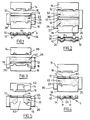
- Figure 1 is a diagrammatic view showing a cross-section of the apparatus used in the first illustrative method of manufacturing a sheet and also shows diagrammatically the sheet manufactured by the first illustrative method;
- Figures 2 to 5 are similar to Figure 1 but illustrate the second to fifth illustrative methods, Figures 2 and 4 also showing the gasket manufactured;
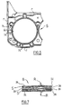
- Figure 6 is a plan view of a portion of a sheet manufactured by the first illustrative method; and
- Figure 7 is a diagrammatic cross-sectional view of a gasket incorporating the sheet shown in Figures 1 and 6.
- The first to the fifth illustrative methods are all methods of manufacturing an embossed steel sheet S at least partially coated with expanded graphite. The sheet S having at least one hole H there-through, the hole H having an embossed ridge R surrounding it. In each of the illustrative methods, a substantially
planar steel sheet 10 is first cut to the outline shape required for the finished gasket G and a layer ofadhesive 12 is applied to a surface of thesheet 10. It is not, however, necessary to apply the adhesive after cutting thesheet 10 to its outline shape and the cutting to outline shape can be left until the end of the illustrative method. Thesheet 10 can be cut out by any of the usual methods and theadhesive 12 can also be applied by any of the usual methods. The adhesive may be, for example, a nitrile-phenolic adhesive which is applied as a solution and, after the expanded graphite has been applied thereto, requires heating to cross-link the adhesive. - The apparatuses used in each of the five illustrative methods are similar in many respects and like parts in the five apparatuses are given the same reference numerals in the drawings and are only described in detail in relation to the first illustrative method.
- The apparatus shown in Figure 1 is used in the first illustrative method. This apparatus comprises an
upper embossing die 14 which is mounted on the upper platen of a press (not shown). The die 14 has aprotuberance 16 extending downwardly therefrom which is arranged to emboss the ridge R into thesheet 10 so that, in the finished sheet S, the ridge R extends around the hole H. In this case, the hole H is circular so that theprotuberance 16 is also circular having a greater diameter than the hole H. Theprotuberance 16 is itself of approximately semi-circular cross-section so that it provides a ridge also of approximately semi-circular cross-section. However, as shown in Figure 7, the ridge R may be of V-shaped cross-section. The apparatus also comprises alower embossing die 18 which is mounted on a lower platen of the afore-mentioned press (not shown) in opposed relationship with the die 14. The lower embossing die 18 has arecess 20 therein which is complementary to theprotuberance 16 and is arranged to receive the ridge embossed in to thesheet 10. - The first illustrative method comprises positioning the
upper embossing die 14, and thelower embossing die 18 on the press in opposed relationship, positioning the metallic,planar sheet 10 between thedies particles 22 of expanded graphite between thelower die 18 and the layer ofadhesive 12 on thesheet 10. The method also comprises pressing thedies layer 22, so that they coalesce and form acoating 24 adhered to theadhesive layer 12, and simultaneously embossing the ridge R into thesheet 10 and thecoating 24. - In order to position the layer of
particles 22, the apparatus used in the first illustrative method also comprises a particle-retaining wall 26. Thewall 26 forms an enclosed rectangle, open at the top and at the bottom so that it can surround thelower embossing die 18 and project upwardly therefrom to a substantially equal extent around the periphery of thewall 26. Theupper embossing die 14 can fit into thewall 26 as can thesheet 10. - In order to position the layer of
particles 22, in the first illustrative method, the space defined by thewall 26 above thelower die 18 is filled with the particles of expanded graphite and theparticle layer 22 is skimmed off level with the top of thewall 26. This ensures a substantially uniform layer of particles on thelower die 18 which is confined at its edges by thewall 26. Thewall 26 is then raised relative to thelower die 18 and the reinforcingsheet 10 is positioned within thewall 26 on top of thelayer 22 with theadhesive layer 12 facing downwardly and in contact with the layer 22 (this condition is shown in Figure 1). Thedies layer 22, so that they coalesce and form thecoating 24 adhered to theadhesive layer 12. In this process theupper embossing die 14 is moved downwardly into thewall 26 and engages thesheet 10 pressing it downwardly towards thelower die 18 so that thelayer 22 is compressed between thesheet 10 and thedie 18. The pressing process which is carried out by operation of the afore-mentioned press also embosses the ridge R into thesheet 10 and thecoating 24. - In the first illustrative method, the hole H is punched through the gasket G after the expanded
graphite coating 24 has been adhered to thesheet 10. This can be achieved by a punching operation of conventional type. - Figure 6 illustrates that the sheet S may have further ridges r and holes h which can be formed in the same operations as the ridge R and the hole H.
- Figure 7 shows that the sheet S can be used in a stack-type gasket G. In this case, the opposite surface of the sheet S is coated with nitrile rubber, by a conventional method, to give a
coating 28. Thecoating 28 engages aplanar steel sheet 29 of the stack. The stack is completed by an inverted version of the sheet S whosecoating 28 also engages thesheet 29. - Figure 2 illustrates the apparatus used in the second illustrative method. In the second illustrative method, a further layer of adhesive 30 is applied to an opposite surface of the reinforcing
sheet 10 to theadhesive layer 12 and a further layer ofparticles 32 is assembled between the layer of adhesive 30 and theupper die 14. The second illustrative method is otherwise identical to the first illustrative method described above. In the pressing operation, the die 14 compresses thelayer 32 to form afurther coating 34 adhered to thelayer 30 of adhesive. The further layer ofparticles 32 is positioned by filling the space defined by thewall 26 above the reinforcingsheet 10 after the latter has been positioned within thewall 26 on thelayer 22 and thewall 26 has been raised for a second time. Thefurther layer 32 is also skimmed level with the top of thewall 26 before the pressing operation begins. The sheet S produced by the second illustrative method is suitable for use as a gasket itself. - Figure 3 illustrates the third illustrative method, which is similar to the first illustrative method except that the
sheet 10 is positioned on thelower die 18 within thewall 26 with thelayer 12 uppermost without previously forming a layer of particles on top of thedie 18. Also, theprotuberance 16 is provided on thelower die 18 and therecess 20 is in theupper die 14. The third illustrative method continues by filling the space defined by thewall 26 above thesheet 10 with particles of expanded graphite to form alayer 40 and skimming theparticle layer 40 level with the top of thewall 26. The third illustrative method then continues in similar fashion to the first illustrative method with the pressing operation forming acoating 24 adhered to theadhesive layer 12. - In the first, second and third illustrative methods, the hole H is cut out from the gasket after the expanded graphite has been applied to the
sheet 10. In the fourth illustrative method, however, illustrated by Figure 4, the hole H is cut out from the sheet in two stages. In a first stage, performed before the expanded graphite is applied to thesheet 10, asmaller hole 50 is punched out of thesheet 10 and thecoating 24 is applied and the ridge R is embossed as in the first illustrative method. In a second, hole trimming, stage performed on the embossed sheet S, thehole 50 is enlarged by punching out a ring around it of the metal and of graphite adhered thereto. - In the fifth illustrative method shown in Figure 5, the hole H is cut through the
sheet 10 before thesheet 10 is positioned between the dies 14 and 18. In this case, thelower die 18 has afurther protuberance 60 which is generally cylindrical and enters the hole H in thesheet 10 and acorresponding recess 62 in thedie 14. Theprotuberance 60 acts to blank off the hole H in thesheet 10 so that expanded graphite is not required in the area which will form the hole H. - It will be apparent that various combinations of the five illustrative methods can be used. For example, a protuberance similar to the
protuberance 60 can be utilised in a method similar to the first illustrative method.
Claims (10)
- A method of manufacturing an embossed metallic sheet (S) coated at least partially with expanded graphite and suitable for use as a gasket (G) or as a component layer of a gasket, the method comprising positioning a substantially planar metallic sheet (10) between an upper embossing die (14) and a lower embossing die (18) with a layer (22) of particles of expanded graphite between one of said dies and a surface of the sheet, one of said dies having at least one protuberance (16) arranged to emboss a ridge (R) into the sheet (10) and the other of said dies having a corresponding recess (20) complementary to the protuberance, the method also comprising pressing said dies together thereby compressing the particles of expanded graphite, so that they coalesce and form a coating (24) attached to said sheet, and simultaneously embossing the ridge into the sheet and the coating.
- A method according to Claim 1, characterised in that said layer (22) of particles is positioned by providing a particle retaining wall (26) surrounding the lower embossing die (18) and projecting upwardly therefrom to a substantially equal extent around the periphery of the wall, filling the space defined by the wall above the lower die with particles of expanded graphite, and skimming the particle layer level with the top of said wall, the planar metallic sheet (10) then being positioned on top of the layer of particles.
- A method according to either one of Claims 1 and 2, characterised in that a further layer of particles (32) is positioned between said planar sheet (10) and the other of said dies (14,18), and the two layers are pressed into coatings (24,34) simultaneously.
- A method according to Claim 3 when dependent on Claim 2, characterised in that the further layer (32) of particles is positioned by raising said wall (26) relative to the lower die (18) after positioning the planar sheet (10), filling the space defined by said wall above the planar sheet with particles, and skimming the further particle layer level with the top of said wall.
- A method according to Claim 1, characterised in that the method comprises providing a particle retaining wall (26) surrounding the lower embossing die (18) and projecting upwardly therefrom to a substantially equal extent around the periphery of the wall, positioning the planar sheet (10) on the lower die (18) within said wall (26), filling the space defined by the wall above the planar sheet with particles of expanded graphite, and skimming the particle layer level with the top of the wall.
- A method according to any one of Claims 1 to 5, characterised in that at least one hole (H) is cut out from the sheet in two stages, a first stage in which a smaller hole (50) is punched out, the first stage being performed before the expanded graphite is applied to the planar sheet (10), and a second, hole trimming, stage in which the hole (50) is enlarged by punching out a ring around it, the second stage being performed on the embossed sheet (S).
- A method according to any one of Claims 1 to 5, characterised in that during the application of expanded graphite to said planar sheet (10), a hole (H) therein is blanked off by a further protuberance (60) from one of said dies (14,18) which enters a corresponding recess (62) in the other die.
- A method according to any one of Claims 1 to 7, characterised in that the method also comprises applying a layer of adhesive (12) to one or both surfaces of the planar sheet (10) before it is positioned between the dies.
- A method according to any one of Claims 1 to 8, characterised in that the particles have their mean dimensions in the range 0.2 to 2mm.
- A method according to any one of Claims 1 to 10, characterised in that the particle layer (22) has a thickness of between 2 and 5mm.
Applications Claiming Priority (3)
| Application Number | Priority Date | Filing Date | Title |
|---|---|---|---|
| GB929216604A GB9216604D0 (en) | 1992-08-05 | 1992-08-05 | Gasket manufacture |
| GB9216604 | 1992-08-05 | ||
| PCT/GB1993/001480 WO1994003742A1 (en) | 1992-08-05 | 1993-07-14 | Gasket manufacture |
Publications (2)
| Publication Number | Publication Date |
|---|---|
| EP0654130A1 EP0654130A1 (en) | 1995-05-24 |
| EP0654130B1 true EP0654130B1 (en) | 1997-09-03 |
Family
ID=10719847
Family Applications (1)
| Application Number | Title | Priority Date | Filing Date |
|---|---|---|---|
| EP93916073A Expired - Lifetime EP0654130B1 (en) | 1992-08-05 | 1993-07-14 | Gasket manufacture |
Country Status (9)
| Country | Link |
|---|---|
| US (1) | US5570501A (en) |
| EP (1) | EP0654130B1 (en) |
| JP (1) | JPH07509770A (en) |
| AT (1) | ATE157755T1 (en) |
| AU (1) | AU662072B2 (en) |
| DE (1) | DE69313648T2 (en) |
| GB (1) | GB9216604D0 (en) |
| WO (1) | WO1994003742A1 (en) |
| ZA (1) | ZA935473B (en) |
Families Citing this family (12)
| Publication number | Priority date | Publication date | Assignee | Title |
|---|---|---|---|---|
| US7482085B2 (en) * | 1996-06-07 | 2009-01-27 | Bdf Ip Holdings Ltd. | Apparatus for improving the cold starting capability of an electrochemical fuel cell |
| US6540852B1 (en) | 1998-07-21 | 2003-04-01 | Acadia Elastomers Corporation | Apparatus and method for manufacturing gaskets |
| CH710862B1 (en) | 1999-11-26 | 2016-09-15 | Imerys Graphite & Carbon Switzerland Sa | Process for the production of graphite powders with increased bulk density. |
| US6797091B2 (en) * | 2000-05-10 | 2004-09-28 | Ballard Power Systems Inc. | Method for embossing expanded graphite sheet material under reduced pressure |
| US20030051797A1 (en) * | 2000-05-10 | 2003-03-20 | Lines Donald A. | Method for embossing expanded graphite sheet material under reduced pressure |
| US6716381B2 (en) | 2001-04-04 | 2004-04-06 | Advanced Energy Technology Inc. | Process for preparing embossed flexible graphite article |
| US7341781B2 (en) | 2001-04-04 | 2008-03-11 | Graftech International Holdings Inc. | Material useful for preparing embossed flexible graphite article |
| JP2007503316A (en) * | 2003-08-26 | 2007-02-22 | パーカー−ハニフイン・コーポレーシヨン | Structure of gasket with holder |
| CN107002877B (en) * | 2014-11-13 | 2018-06-01 | Nok株式会社 | The sealing structure of babinet |
| DE102015107032A1 (en) * | 2015-05-06 | 2016-11-10 | Ccl Design Gmbh | Method for producing a stamped component |
| KR102069175B1 (en) * | 2017-01-06 | 2020-01-22 | 주식회사 엘지화학 | Cap Assembly for Cylindrical Secondary Battery Comprising Current Interrupt Device Coated with Insulating Material on Outer Circumference Surface |
| CN111720542B (en) * | 2020-06-01 | 2022-05-31 | 无锡宝亿沣密封材料有限公司 | Forming process method of metal graphite symbiotic high-temperature fluid sealing element |
Family Cites Families (13)
| Publication number | Priority date | Publication date | Assignee | Title |
|---|---|---|---|---|
| US2444394A (en) * | 1943-03-11 | 1948-06-29 | Lane Wells Co | Method of molding diaphragms |
| US3028667A (en) * | 1958-04-07 | 1962-04-10 | Arvin Ind Inc | Method of forming laminated articles |
| EP0052484B1 (en) * | 1980-11-15 | 1985-05-02 | T&N Materials Research Limited | Improvements in and relating to gasket manufacture |
| GB2128271B (en) * | 1982-10-01 | 1986-02-05 | T & N Materials Res Ltd | Mature graphite gaskets |
| GB2145960B (en) * | 1983-09-03 | 1986-12-31 | Payen Int Ltd | Moulding graphitized sealing gasket |
| GB2146712B (en) * | 1983-09-16 | 1986-07-30 | Payen Int Ltd | Making gaskets |
| GB2156012B (en) * | 1984-03-24 | 1987-03-18 | T & N Materials Res Ltd | Making gaskets from expanded graphite |
| JP2518653B2 (en) * | 1987-07-29 | 1996-07-24 | 日本カ−ボン株式会社 | Gasket for internal combustion engine |
| US4876876A (en) * | 1987-10-27 | 1989-10-31 | Mazda Motor Corporation | Dies for forging gear-shaped part made of sheet metal |
| JPH01187349A (en) * | 1988-01-20 | 1989-07-26 | Hitachi Chem Co Ltd | Graphite head gasket |
| US4830698A (en) * | 1988-04-20 | 1989-05-16 | Fel-Pro Incorporated | Method of forming a gasket with enhanced sealing characteristics |
| WO1993008420A1 (en) * | 1991-10-21 | 1993-04-29 | Mccord Payen Incorporated | Embossed composite gasket |
| US5226662A (en) * | 1992-07-07 | 1993-07-13 | Fel-Pro Incorporated | Expanded graphite and metal core automotive head gasket |
-
1992
- 1992-08-05 GB GB929216604A patent/GB9216604D0/en active Pending
-
1993
- 1993-07-14 AT AT93916073T patent/ATE157755T1/en not_active IP Right Cessation
- 1993-07-14 EP EP93916073A patent/EP0654130B1/en not_active Expired - Lifetime
- 1993-07-14 WO PCT/GB1993/001480 patent/WO1994003742A1/en not_active Ceased
- 1993-07-14 AU AU45776/93A patent/AU662072B2/en not_active Ceased
- 1993-07-14 US US08/351,277 patent/US5570501A/en not_active Expired - Fee Related
- 1993-07-14 JP JP6505078A patent/JPH07509770A/en active Pending
- 1993-07-14 DE DE69313648T patent/DE69313648T2/en not_active Expired - Fee Related
- 1993-07-29 ZA ZA935473A patent/ZA935473B/en unknown
Also Published As
| Publication number | Publication date |
|---|---|
| GB9216604D0 (en) | 1992-09-16 |
| US5570501A (en) | 1996-11-05 |
| EP0654130A1 (en) | 1995-05-24 |
| AU662072B2 (en) | 1995-08-17 |
| WO1994003742A1 (en) | 1994-02-17 |
| JPH07509770A (en) | 1995-10-26 |
| DE69313648D1 (en) | 1997-10-09 |
| DE69313648T2 (en) | 1998-03-19 |
| AU4577693A (en) | 1994-03-03 |
| ZA935473B (en) | 1994-02-23 |
| ATE157755T1 (en) | 1997-09-15 |
Similar Documents
| Publication | Publication Date | Title |
|---|---|---|
| US5570501A (en) | Gasket manufacture | |
| CN1031982C (en) | Apparatus and method for cutting blanks | |
| JPS617027A (en) | Method and device for combining metallic sheet | |
| US4810454A (en) | Method of manufacturing a gasket having multiple regions of different densities and thicknesses | |
| EP0052484A1 (en) | Improvements in and relating to gasket manufacture | |
| US20060147732A1 (en) | Metal plate, method for making same and method for folding same | |
| JP2000117344A (en) | Pressing method of metallic product and progressive working method | |
| GB2269332A (en) | Gasket manufacture | |
| US5340525A (en) | Method of forming a sealing bead on a gasket | |
| JPH0368770B2 (en) | ||
| EP0134712B1 (en) | Method of making a gasket | |
| JP2964409B2 (en) | Gasket manufacturing method | |
| WO1985000865A1 (en) | Cam shaft and method of manufacturing thereof | |
| JP3804838B2 (en) | Manufacturing method of laminate | |
| JPH04167933A (en) | Cutting/forming machine of panel | |
| JPH08132156A (en) | Metallic laminated plate and its manufacture | |
| JPS6114027A (en) | Blanking method of composite plate and blanking die | |
| AU772674B2 (en) | Core plug formation | |
| JPS62214834A (en) | Punching method for clad plate | |
| JPH058079Y2 (en) | ||
| JP3845785B2 (en) | Drilling method | |
| JPH03221217A (en) | Forming method for plate material | |
| JPS59195805A (en) | Laminated core | |
| JPH0623615U (en) | Parts positioning protrusion die | |
| GB2206656A (en) | Gasket and method of manufacture |
Legal Events
| Date | Code | Title | Description |
|---|---|---|---|
| PUAI | Public reference made under article 153(3) epc to a published international application that has entered the european phase |
Free format text: ORIGINAL CODE: 0009012 |
|
| 17P | Request for examination filed |
Effective date: 19941021 |
|
| AK | Designated contracting states |
Kind code of ref document: A1 Designated state(s): AT BE DE ES FR GB IT NL PT SE |
|
| 17Q | First examination report despatched |
Effective date: 19960415 |
|
| GRAG | Despatch of communication of intention to grant |
Free format text: ORIGINAL CODE: EPIDOS AGRA |
|
| GRAH | Despatch of communication of intention to grant a patent |
Free format text: ORIGINAL CODE: EPIDOS IGRA |
|
| GRAH | Despatch of communication of intention to grant a patent |
Free format text: ORIGINAL CODE: EPIDOS IGRA |
|
| GRAA | (expected) grant |
Free format text: ORIGINAL CODE: 0009210 |
|
| AK | Designated contracting states |
Kind code of ref document: B1 Designated state(s): AT BE DE ES FR GB IT NL PT SE |
|
| PG25 | Lapsed in a contracting state [announced via postgrant information from national office to epo] |
Ref country code: NL Free format text: LAPSE BECAUSE OF FAILURE TO SUBMIT A TRANSLATION OF THE DESCRIPTION OR TO PAY THE FEE WITHIN THE PRESCRIBED TIME-LIMIT Effective date: 19970903 Ref country code: IT Free format text: LAPSE BECAUSE OF FAILURE TO SUBMIT A TRANSLATION OF THE DESCRIPTION OR TO PAY THE FEE WITHIN THE PRE;WARNING: LAPSES OF ITALIAN PATENTS WITH EFFECTIVE DATE BEFORE 2007 MAY HAVE OCCURRED AT ANY TIME BEFORE 2007. THE CORRECT EFFECTIVE DATE MAY BE DIFFERENT FROM THE ONE RECORDED.SCRIBED TIME-LIMIT Effective date: 19970903 Ref country code: ES Free format text: THE PATENT HAS BEEN ANNULLED BY A DECISION OF A NATIONAL AUTHORITY Effective date: 19970903 Ref country code: BE Effective date: 19970903 Ref country code: AT Effective date: 19970903 |
|
| REF | Corresponds to: |
Ref document number: 157755 Country of ref document: AT Date of ref document: 19970915 Kind code of ref document: T |
|
| REF | Corresponds to: |
Ref document number: 69313648 Country of ref document: DE Date of ref document: 19971009 |
|
| ET | Fr: translation filed | ||
| PG25 | Lapsed in a contracting state [announced via postgrant information from national office to epo] |
Ref country code: SE Effective date: 19971203 Ref country code: PT Effective date: 19971203 |
|
| NLV1 | Nl: lapsed or annulled due to failure to fulfill the requirements of art. 29p and 29m of the patents act | ||
| PLBE | No opposition filed within time limit |
Free format text: ORIGINAL CODE: 0009261 |
|
| STAA | Information on the status of an ep patent application or granted ep patent |
Free format text: STATUS: NO OPPOSITION FILED WITHIN TIME LIMIT |
|
| 26N | No opposition filed | ||
| PGFP | Annual fee paid to national office [announced via postgrant information from national office to epo] |
Ref country code: FR Payment date: 19990615 Year of fee payment: 7 |
|
| PGFP | Annual fee paid to national office [announced via postgrant information from national office to epo] |
Ref country code: GB Payment date: 19990618 Year of fee payment: 7 |
|
| PGFP | Annual fee paid to national office [announced via postgrant information from national office to epo] |
Ref country code: DE Payment date: 19990628 Year of fee payment: 7 |
|
| PG25 | Lapsed in a contracting state [announced via postgrant information from national office to epo] |
Ref country code: GB Free format text: LAPSE BECAUSE OF NON-PAYMENT OF DUE FEES Effective date: 20000714 |
|
| GBPC | Gb: european patent ceased through non-payment of renewal fee |
Effective date: 20000714 |
|
| PG25 | Lapsed in a contracting state [announced via postgrant information from national office to epo] |
Ref country code: FR Free format text: LAPSE BECAUSE OF NON-PAYMENT OF DUE FEES Effective date: 20010330 |
|
| REG | Reference to a national code |
Ref country code: FR Ref legal event code: ST |
|
| PG25 | Lapsed in a contracting state [announced via postgrant information from national office to epo] |
Ref country code: DE Free format text: LAPSE BECAUSE OF NON-PAYMENT OF DUE FEES Effective date: 20010501 |