EP0653573A1 - Ball joint - Google Patents
Ball joint Download PDFInfo
- Publication number
- EP0653573A1 EP0653573A1 EP94117642A EP94117642A EP0653573A1 EP 0653573 A1 EP0653573 A1 EP 0653573A1 EP 94117642 A EP94117642 A EP 94117642A EP 94117642 A EP94117642 A EP 94117642A EP 0653573 A1 EP0653573 A1 EP 0653573A1
- Authority
- EP
- European Patent Office
- Prior art keywords
- bearing shell
- ball
- joint
- joint housing
- ball joint
- Prior art date
- Legal status (The legal status is an assumption and is not a legal conclusion. Google has not performed a legal analysis and makes no representation as to the accuracy of the status listed.)
- Granted
Links
Images


Classifications
-
- F—MECHANICAL ENGINEERING; LIGHTING; HEATING; WEAPONS; BLASTING
- F16—ENGINEERING ELEMENTS AND UNITS; GENERAL MEASURES FOR PRODUCING AND MAINTAINING EFFECTIVE FUNCTIONING OF MACHINES OR INSTALLATIONS; THERMAL INSULATION IN GENERAL
- F16C—SHAFTS; FLEXIBLE SHAFTS; ELEMENTS OR CRANKSHAFT MECHANISMS; ROTARY BODIES OTHER THAN GEARING ELEMENTS; BEARINGS
- F16C11/00—Pivots; Pivotal connections
- F16C11/04—Pivotal connections
- F16C11/06—Ball-joints; Other joints having more than one degree of angular freedom, i.e. universal joints
- F16C11/0619—Ball-joints; Other joints having more than one degree of angular freedom, i.e. universal joints the female part comprising a blind socket receiving the male part
- F16C11/0623—Construction or details of the socket member
- F16C11/0628—Construction or details of the socket member with linings
- F16C11/0633—Construction or details of the socket member with linings the linings being made of plastics
- F16C11/0638—Construction or details of the socket member with linings the linings being made of plastics characterised by geometrical details
-
- B—PERFORMING OPERATIONS; TRANSPORTING
- B62—LAND VEHICLES FOR TRAVELLING OTHERWISE THAN ON RAILS
- B62D—MOTOR VEHICLES; TRAILERS
- B62D7/00—Steering linkage; Stub axles or their mountings
- B62D7/16—Arrangement of linkage connections
-
- F—MECHANICAL ENGINEERING; LIGHTING; HEATING; WEAPONS; BLASTING
- F16—ENGINEERING ELEMENTS AND UNITS; GENERAL MEASURES FOR PRODUCING AND MAINTAINING EFFECTIVE FUNCTIONING OF MACHINES OR INSTALLATIONS; THERMAL INSULATION IN GENERAL
- F16C—SHAFTS; FLEXIBLE SHAFTS; ELEMENTS OR CRANKSHAFT MECHANISMS; ROTARY BODIES OTHER THAN GEARING ELEMENTS; BEARINGS
- F16C11/00—Pivots; Pivotal connections
- F16C11/04—Pivotal connections
- F16C11/06—Ball-joints; Other joints having more than one degree of angular freedom, i.e. universal joints
- F16C11/0619—Ball-joints; Other joints having more than one degree of angular freedom, i.e. universal joints the female part comprising a blind socket receiving the male part
- F16C11/0623—Construction or details of the socket member
- F16C11/0642—Special features of the plug or cover on the blind end of the socket
-
- F—MECHANICAL ENGINEERING; LIGHTING; HEATING; WEAPONS; BLASTING
- F16—ENGINEERING ELEMENTS AND UNITS; GENERAL MEASURES FOR PRODUCING AND MAINTAINING EFFECTIVE FUNCTIONING OF MACHINES OR INSTALLATIONS; THERMAL INSULATION IN GENERAL
- F16C—SHAFTS; FLEXIBLE SHAFTS; ELEMENTS OR CRANKSHAFT MECHANISMS; ROTARY BODIES OTHER THAN GEARING ELEMENTS; BEARINGS
- F16C11/00—Pivots; Pivotal connections
- F16C11/04—Pivotal connections
- F16C11/06—Ball-joints; Other joints having more than one degree of angular freedom, i.e. universal joints
- F16C11/068—Special features relating to lubrication
-
- F—MECHANICAL ENGINEERING; LIGHTING; HEATING; WEAPONS; BLASTING
- F16—ENGINEERING ELEMENTS AND UNITS; GENERAL MEASURES FOR PRODUCING AND MAINTAINING EFFECTIVE FUNCTIONING OF MACHINES OR INSTALLATIONS; THERMAL INSULATION IN GENERAL
- F16C—SHAFTS; FLEXIBLE SHAFTS; ELEMENTS OR CRANKSHAFT MECHANISMS; ROTARY BODIES OTHER THAN GEARING ELEMENTS; BEARINGS
- F16C11/00—Pivots; Pivotal connections
- F16C11/04—Pivotal connections
- F16C11/06—Ball-joints; Other joints having more than one degree of angular freedom, i.e. universal joints
- F16C11/0685—Manufacture of ball-joints and parts thereof, e.g. assembly of ball-joints
- F16C11/069—Manufacture of ball-joints and parts thereof, e.g. assembly of ball-joints with at least one separate part to retain the ball member in the socket; Quick-release systems
-
- F—MECHANICAL ENGINEERING; LIGHTING; HEATING; WEAPONS; BLASTING
- F16—ENGINEERING ELEMENTS AND UNITS; GENERAL MEASURES FOR PRODUCING AND MAINTAINING EFFECTIVE FUNCTIONING OF MACHINES OR INSTALLATIONS; THERMAL INSULATION IN GENERAL
- F16C—SHAFTS; FLEXIBLE SHAFTS; ELEMENTS OR CRANKSHAFT MECHANISMS; ROTARY BODIES OTHER THAN GEARING ELEMENTS; BEARINGS
- F16C33/00—Parts of bearings; Special methods for making bearings or parts thereof
- F16C33/02—Parts of sliding-contact bearings
- F16C33/04—Brasses; Bushes; Linings
- F16C33/06—Sliding surface mainly made of metal
- F16C33/10—Construction relative to lubrication
- F16C33/102—Construction relative to lubrication with grease as lubricant
-
- F—MECHANICAL ENGINEERING; LIGHTING; HEATING; WEAPONS; BLASTING
- F16—ENGINEERING ELEMENTS AND UNITS; GENERAL MEASURES FOR PRODUCING AND MAINTAINING EFFECTIVE FUNCTIONING OF MACHINES OR INSTALLATIONS; THERMAL INSULATION IN GENERAL
- F16C—SHAFTS; FLEXIBLE SHAFTS; ELEMENTS OR CRANKSHAFT MECHANISMS; ROTARY BODIES OTHER THAN GEARING ELEMENTS; BEARINGS
- F16C2326/00—Articles relating to transporting
- F16C2326/20—Land vehicles
- F16C2326/24—Steering systems, e.g. steering rods or columns
-
- Y—GENERAL TAGGING OF NEW TECHNOLOGICAL DEVELOPMENTS; GENERAL TAGGING OF CROSS-SECTIONAL TECHNOLOGIES SPANNING OVER SEVERAL SECTIONS OF THE IPC; TECHNICAL SUBJECTS COVERED BY FORMER USPC CROSS-REFERENCE ART COLLECTIONS [XRACs] AND DIGESTS
- Y10—TECHNICAL SUBJECTS COVERED BY FORMER USPC
- Y10T—TECHNICAL SUBJECTS COVERED BY FORMER US CLASSIFICATION
- Y10T403/00—Joints and connections
- Y10T403/32—Articulated members
- Y10T403/32606—Pivoted
- Y10T403/32631—Universal ball and socket
- Y10T403/32721—Elastomeric seat
-
- Y—GENERAL TAGGING OF NEW TECHNOLOGICAL DEVELOPMENTS; GENERAL TAGGING OF CROSS-SECTIONAL TECHNOLOGIES SPANNING OVER SEVERAL SECTIONS OF THE IPC; TECHNICAL SUBJECTS COVERED BY FORMER USPC CROSS-REFERENCE ART COLLECTIONS [XRACs] AND DIGESTS
- Y10—TECHNICAL SUBJECTS COVERED BY FORMER USPC
- Y10T—TECHNICAL SUBJECTS COVERED BY FORMER US CLASSIFICATION
- Y10T403/00—Joints and connections
- Y10T403/32—Articulated members
- Y10T403/32606—Pivoted
- Y10T403/32631—Universal ball and socket
- Y10T403/32737—Universal ball and socket including liner, shim, or discrete seat
- Y10T403/32778—Completely spacing the members
Definitions
- the invention relates to a ball joint for motor vehicles with a bearing shell made of an elastic plastic inserted between a joint housing and a ball head of a rotatable or tiltable ball pin, which is supported with its outer surface in the joint housing, under the influence of a joint preload or load on the inside the bearing shell lubrication pockets are formed.
- Such ball joints are known. They allow both a twisting and a tilting movement of the components connected to one another via the joint. In particular, when several ball joints interact, e.g. in the suspension of steerable front wheels, the friction generated between the bearing shell and the ball head is kept as low as possible.
- the lubrication pockets formed by the ribs have a relatively large area, so that on the one hand an undesirable elasticity of the joint arises and on the other hand a relatively large loosening torque is necessary due to the ribs in order to generate a relative movement between the ball head and the bearing shell.
- This high loosening torque is particularly undesirable in the case of a plurality of interacting ball joints, for example in multi-link axles of motor vehicles.
- the amount of the loosening torque and the resulting friction is dependent on the direction of movement of the ball head relative to the ribs formed on the bearing shell due to the elongated extension of the ribs.
- the known ribs have the disadvantage that their effect is only achieved with narrow manufacturing tolerances, in particular of the joint housing.
- the object of the invention is to develop a ball joint of the type described in the introduction in such a way that there is a low loosening torque with improved lubrication and thus a longer service life.
- the bearing shell on its surface adjacent to the joint housing is provided with a plurality of flats or elevations evenly distributed on the surface and, when the ball joint is mounted, the outer surface of the bearing shell due to the grease filling and the elasticity of the plastic material of the bearing shell Bearing shell also bears in the area of the flattened areas or outside the area of the elevations on the joint housing and thereby form lubrication pockets on the inside of the bearing shell facing the smooth ball head.
- the majority of the flattened portions or elevations form smaller lubrication pockets of a defined shape, so that the size of the loosening torque is reduced and undesirable elasticity of the joints is avoided.
- the lubricant flows from one lubrication pocket to the next, so that a kind of hydrodynamic lubrication results and the components slide almost frictionlessly. Due to the even distribution of the lubrication pockets formed by the flats, not only is full-surface lubrication necessary ensures a low overall lubricant requirement, but there is also a low loosening torque that is independent of the direction of movement.
- the flats or elevations can be arranged in several rows on the degrees of longitude and latitude of the spherical surface. With such a distribution, depending on the design and size of the lubrication pockets, either the same or deliberately different frictional forces and / or loosening moments in the direction of rotation and tilting can be achieved.
- a protruding collar is arranged on the outside of the bearing shell, with which the bearing shell is non-positively fixed to the joint housing by clamping.
- the clamping is achieved by a locking ring, through which the bearing shell is held non-rotatably in the joint housing.
- the fixed bearing shell also lies in a form-fitting manner on the joint housing, which enables a direct transmission of the forces through the joint and creates a joint connection without play.
- the ball joint can be easily mounted by clamping the bearing shell using the locking ring.
- the bearing shell is preferably extended to enlarge the bearing surface over the collar in the direction of the ball stud, and in order to improve the lubrication, the extension can also be provided with flats or elevations forming lubrication pockets.
- FIG. 1 shows a ball joint with a ball pin 1, the ball head 2 of which is inserted into a joint housing 40 with the interposition of a bearing shell 30.
- the joint housing 40 receives the bearing shell 30 in a hemispherical recess 41.
- a locking ring 50 is inserted into the joint housing 40, through the spherical ring-shaped inner surface 51 of which the recess 41 is extended to form a spherical cap with an opening 52 for the ball pin 1.
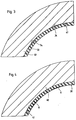
- a first exemplary embodiment of the bearing shell 30 inserted between the joint housing 40 and the ball head 2 is shown in a side view in FIG. 2.
- the bearing shell 30 comprises an approximately hemispherical upper part 31, a collar 32 adjoining the upper part 31 and a cylindrical extension 33 adjoining the collar.
- Flats 34 are provided on the surface of the upper part 31 and the extension 33 of the bearing shell 30.
- the flats 34 are formed in the manner of the base of spherical caps as planes formed tangentially on the outer surface of the bearing shell 30. As can be clearly seen in FIG. 2, the edge of each flat 34 has a circular shape. Overall, the flats 34 are in several rows on the length and Latitudes of the spherical surface of the bearing shell 30 are arranged. A series of flats 34 is also formed on the extension 33.
- the bearing shell 30 inserted into the joint housing 40 is supported on the latter.
- the spherical head 2 is enclosed by the bearing shell 30 at an angle of more than 180 °, since, as can be seen in FIG. 1, the elastic plastic material of the extension 33 is formed by the inner surface 51 of the locking ring 50 to form a ring segment of a spherical shell .
- This shape of the locking ring 50 not only increases the contact area between the ball head 2 and the bearing shell 30; the ball head 2 is also captively received in the joint housing 40.
- the bearing shell 30 is non-positively fixed by clamping in the joint housing 40, since the collar 32 is enclosed between the joint housing 40 and the locking ring 50.
- the extension 33 is dimensioned such that it is flush with the opening 52.
- the bearing shell 30 inserted into the joint housing 40 lies against the recess 41 with its outer surface. Only in the area of the flats 34 does the bearing shell 30 run at a distance from the recess 41. Under the influence of a joint prestress or stress on the inside of the bearing shell 30, the fat filling introduced into the ball joint is compressed, so that the elastic plastic material of the bearing shell 30 is deformed in this way is that the outer surface of the bearing shell 30 also abuts the recess 41 in the area of the flats 34, so that on the inside of the bearing shell 30 both in the area of the upper part 31 and the extension 33 due to the flats 34 lubrication pockets 6, which form with Are filled with fat. These lubrication pockets 6 are identified by hatching in FIG. 5.
- elevations 35 are formed on the surface of the bearing shell 30 instead of flattened portions, which in turn are circular or oval.
Abstract
Description
Die Erfindung betrifft ein Kugelgelenk für Kraftfahrzeuge mit einer zwischen einem Gelenkgehäuse und einem Kugelkopf eines dreh- bzw. kippbeweglichen Kugelzapfens eingesetzten Lagerschale aus einem elastischen Kunststoff, die mit ihrer Außenfläche im Gelenkgehäuse abgestützt ist, wobei unter dem Einfluß einer Gelenkvorspannung oder -belastung auf der Innenseite der Lagerschale Schmiertaschen ausgebildet sind.The invention relates to a ball joint for motor vehicles with a bearing shell made of an elastic plastic inserted between a joint housing and a ball head of a rotatable or tiltable ball pin, which is supported with its outer surface in the joint housing, under the influence of a joint preload or load on the inside the bearing shell lubrication pockets are formed.
Derartige Kugelgelenke sind bekannt. Sie erlauben sowohl eine Verdreh-als auch eine Kippbewegung der über das Gelenk miteinander verbundenen Bauteile. Dabei muß insbesondere beim Zusammenwirken mehrerer Kugelgelenke, z.B. bei der Radaufhängung von lenkbaren Vorderrädern, die zwischen der Lagerschale und dem Kugelkopf erzeugte Reibung so gering wie möglich gehalten werden.Such ball joints are known. They allow both a twisting and a tilting movement of the components connected to one another via the joint. In particular, when several ball joints interact, e.g. in the suspension of steerable front wheels, the friction generated between the bearing shell and the ball head is kept as low as possible.
Aus der DE 33 26 960 C3 ist bereits ein Kugelgelenk bekannt, bei dem die Lagerschale aus elastischem Kunststoff mit ihrer Außenfläche über Rippen an dem Gelenkgehäuse abgestützt ist. Unter dem Einfluß einer Gelenkvorspannung oder -belastung bilden sich auf der Innenseite der Lagerschale in den zwischen den Rippen liegenden Bereichen Schmiertaschen aus, die zu einer verbesserten Schmierung des Kugelgelenks und damit zu einer Verringerung der Reibung führen. Auch die DE 38 23 777 C1 zeigt ein derartiges Kugelgelenk, bei dem die auf der Innenseite der Lagerschale auszubildenden Schmiertaschen durch auf der Lagerschalen-Außenseite angeordnete Rippen gebildet werden, die zur Schaffung eines gleichmäßigen Kipp- und Drehmomentes bezüglich der Gelenkachse schräg verlaufend ausgebildet sind.From DE 33 26 960 C3 a ball joint is already known, in which the bearing shell made of elastic plastic is supported with its outer surface via ribs on the joint housing. Under the influence of a joint preload or load, lubrication pockets form on the inside of the bearing shell in the areas lying between the ribs, which lead to improved lubrication of the ball joint and thus to a reduction in friction. DE 38 23 777 C1 also shows such a ball-and-socket joint, in which the lubrication pockets to be formed on the inside of the bearing shell are formed by ribs arranged on the outside of the bearing shell, which ribs are designed to be oblique with respect to the joint axis in order to create a uniform tilting and torque.
Die durch die Rippen gebildeten Schmiertaschen sind verhältnismäßig großflächig, so daß einerseits eine unerwünschte Gelenkelastizität entsteht und andererseits durch die Rippen ein relativ großes Lösemoment notwendig ist, um eine Relativbewegung zwischen dem Kugelkopf und der Lagerschale zu er-zeugen. Dieses hohe Lösemoment ist insbesondere bei einer Mehrzahl zusammenwirkender Kugelgelenke, beispielsweise bei Mehrlenkerachsen von Kraftfahrzeugen, unerwünscht. Darüber hinaus ist die Höhe des Lösemomentes und die entstehende Reibung aufgrund der länglichen Ausdehnung der Rippen von der Bewegungsrichtung des Kugelkopfes relativ zu den auf der Lagerschale ausgebildeten Rippen abhängig. Außerdem haben die bekannten Rippen den Nachteil, daß ihre Wirkung nur bei engen Fertigungstoleranzen, insbesondere des Gelenkgehäuses erzielt wird.The lubrication pockets formed by the ribs have a relatively large area, so that on the one hand an undesirable elasticity of the joint arises and on the other hand a relatively large loosening torque is necessary due to the ribs in order to generate a relative movement between the ball head and the bearing shell. This high loosening torque is particularly undesirable in the case of a plurality of interacting ball joints, for example in multi-link axles of motor vehicles. In addition, the amount of the loosening torque and the resulting friction is dependent on the direction of movement of the ball head relative to the ribs formed on the bearing shell due to the elongated extension of the ribs. In addition, the known ribs have the disadvantage that their effect is only achieved with narrow manufacturing tolerances, in particular of the joint housing.
Davon ausgehend liegt der Erfindung die Aufgabe zugrunde, ein Kugelgelenk der eingangs beschriebenen Art derart weiterzubilden, daß sich ein geringes Lösemoment bei verbesserter Schmierung und damit Lebensdauer ergibt.Proceeding from this, the object of the invention is to develop a ball joint of the type described in the introduction in such a way that there is a low loosening torque with improved lubrication and thus a longer service life.
Die Lösung dieser Aufgabenstellung ist durch die Erfindung dadurch gekennzeichnet, daß die Lagerschale auf ihrer am Gelenkgehäuse anliegenden Oberfläche mit einer Mehrzahl gleichmäßig auf der Oberfläche verteilter Abflachungen oder Erhebungen versehen ist und bei montiertem Kugelgelenk infolge der Fettfüllung und der Elastizität des Kunststoffmaterials der Lagerschale die Außenfläche der Lagerschale auch im Bereich der Abflachungen bzw. außerhalb des Bereiches der Erhebungen am Gelenkgehäuse anliegt und sich dadurch auf der dem glatten Kugelkopf zugewandten Innenseite der Lagerschale Schmiertaschen bilden.The solution to this problem is characterized by the invention in that the bearing shell on its surface adjacent to the joint housing is provided with a plurality of flats or elevations evenly distributed on the surface and, when the ball joint is mounted, the outer surface of the bearing shell due to the grease filling and the elasticity of the plastic material of the bearing shell Bearing shell also bears in the area of the flattened areas or outside the area of the elevations on the joint housing and thereby form lubrication pockets on the inside of the bearing shell facing the smooth ball head.
Durch die Mehrzahl der ausgebildeten Abflachungen oder Erhebungen werden kleinere Schmiertaschen definierter Form gebildet, so daß die Größe des Lösemomentes verringert und eine unerwünschte Gelenkelastizität vermieden wird. Bei einer Bewegung des Kugelkopfes relativ zu der Lagerschale fließt der Schmierstoff von einer Schmiertasche zu der nächsten, so daß sich eine Art hydrodynamische Schmierung ergibt und die Bauteile nahezu reibungsfrei gleiten. Aufgrund der gleichmäßigen Verteilung der durch die Abflachungen gebildeten Schmiertaschen ist nicht nur eine vollflächige Schmierung bei einem insgesamt geringen Schmierstoffbedarf sichergestellt, sondern es ergibt sich auch ein geringes und von der Bewegungsrichtung unabhängiges Lösemoment.The majority of the flattened portions or elevations form smaller lubrication pockets of a defined shape, so that the size of the loosening torque is reduced and undesirable elasticity of the joints is avoided. When the ball head moves relative to the bearing shell, the lubricant flows from one lubrication pocket to the next, so that a kind of hydrodynamic lubrication results and the components slide almost frictionlessly. Due to the even distribution of the lubrication pockets formed by the flats, not only is full-surface lubrication necessary ensures a low overall lubricant requirement, but there is also a low loosening torque that is independent of the direction of movement.
Gemäß einem weiteren Merkmal der Erfindung können die Abflachungen bzw. Erhebungen in mehreren Reihen auf den Längen- und Breitengraden der kugelförmigen Oberfläche angeordnet sein. Durch eine derartige Verteilung können je nach Ausbildung und Größe der Schmiertaschen entweder gleiche oder gewollt unterschiedliche Reibkräfte und/oder Lösemomente in Verdreh- und Kipprichtung erzielt werden.According to a further feature of the invention, the flats or elevations can be arranged in several rows on the degrees of longitude and latitude of the spherical surface. With such a distribution, depending on the design and size of the lubrication pockets, either the same or deliberately different frictional forces and / or loosening moments in the direction of rotation and tilting can be achieved.
Bei einer vorteilhaften Ausgestaltung der Erfindung ist auf der Außenseite der Lagerschale ein hervorstehender Bund angeordnet, mit dem die Lagerschale durch Klemmung kraftschlüssig an dem Gelenkgehäuse festgelegt ist. Die Klemmung wird durch einen Verschlußring erzielt, durch den die Lagerschale unverdrehbar in dem Gelenkgehäuse gehalten wird. Die festgelegte Lagerschale liegt darüber hinaus formschlüssig an dem Gelenkgehäuse an, wodurch eine direkte Übertragung der Kräfte durch das Gelenk möglich ist und eine Gelenkverbindung ohne Spiel geschaffen wird. Durch das Klemmen der Lagerschale mittels des Verschlußringes ist eine einfache Montage des Kugelgelenkes möglich.In an advantageous embodiment of the invention, a protruding collar is arranged on the outside of the bearing shell, with which the bearing shell is non-positively fixed to the joint housing by clamping. The clamping is achieved by a locking ring, through which the bearing shell is held non-rotatably in the joint housing. The fixed bearing shell also lies in a form-fitting manner on the joint housing, which enables a direct transmission of the forces through the joint and creates a joint connection without play. The ball joint can be easily mounted by clamping the bearing shell using the locking ring.
Vorzugsweise ist die Lagerschale zur Vergrößerung der Lagerfläche über den Bund hinweg in Richtung auf den Kugelzapfen verlängert, wobei zur Verbesserung der Schmierung auch die Verlängerung mit Schmiertaschen bildenden Abflachungen bzw. Erhebungen versehen sein kann.The bearing shell is preferably extended to enlarge the bearing surface over the collar in the direction of the ball stud, and in order to improve the lubrication, the extension can also be provided with flats or elevations forming lubrication pockets.
Auf der Zeichnung sind zwei Ausführungsbeispiele eines erfindungsgemäßen Kugelgelenkes dargestellt, und zwar zeigen:
- Fig. 1
- einen Längsschnitt durch ein erstes Ausführungsbeispiel eines Kugelgelenks,
- Fig. 2
- eine Seitenansicht der Lagerschale des Kugelgelenks nach Fig. 1,
- Fig. 3
- einen vergrößerten Teilschnitt durch die in ein Gehäuse eingesetzte, unbelastete Lagerschale gemäß der Einzelheit III in Fig. 1,
- Fig. 4
- einen vergrößerten Teilschnitt durch das belastete Kugelgelenk gemäß der Einzelheit IV in Fig. 1, und
- Fig. 5
- einen Blick in die belastete Lagerschale gemäß Fig. 4 mit Kennzeichnung der Lagertaschen;
- Fig. 6
- eine Seitenansicht eines zweiten Ausführungsbeispiels einer Lagerschale entsprechend der Darstellung in Fig. 2,
- Fig. 7
- einen Blick in die belastete Lagerschale nach Fig. 6 gemäß der Darstellung in Fig. 5.
- Fig. 1
- 2 shows a longitudinal section through a first exemplary embodiment of a ball joint,
- Fig. 2
- 2 shows a side view of the bearing shell of the ball joint according to FIG. 1,
- Fig. 3
- 2 shows an enlarged partial section through the unloaded bearing shell inserted into a housing according to detail III in FIG. 1,
- Fig. 4
- an enlarged partial section through the loaded ball joint according to detail IV in Fig. 1, and
- Fig. 5
- a look into the loaded bearing shell according to FIG 4 with identification of the bearing pockets.
- Fig. 6
- 2 shows a side view of a second exemplary embodiment of a bearing shell as shown in FIG. 2,
- Fig. 7
- a view of the loaded bearing shell according to FIG. 6 as shown in FIG. 5.
Die Fig. 1 zeigt ein Kugelgelenk mit einem Kugelzapfen 1, dessen Kugelkopf 2 unter Zwischenlage einer Lagerschale 30 in ein Gelenkgehäuse 40 eingesetzt ist. Das Gelenkgehäuse 40 nimmt die Lagerschale 30 in einer halbkugelförmigen Ausnehmung 41 auf. In das Gelenkgehäuse 40 ist ein Verschlußring 50 eingesetzt, durch dessen kugelringförmige Innenfläche 51 die Ausnehmung 41 zu einer Kugelkappe mit einer Öffnung 52 für den Kugelzapfen 1 verlängert wird.1 shows a ball joint with a ball pin 1, the
Ein erstes Ausführungsbeispiel der zwischen dem Gelenkgehäuse 40 und dem Kugelkopf 2 eingesetzten Lagerschale 30 ist in Fig. 2 in einer Seitenansicht dargestellt. Die Lagerschale 30 umfaßt ein etwa halbkugelförmiges Oberteil 31, einen sich an das Oberteil 31 anschließenden Bund 32 sowie eine sich an den Bund anschließende zylinderförmige Verlängerung 33. Auf der Oberfläche des Oberteils 31 sowie der Verlängerung 33 der Lagerschale 30 sind Abflachungen 34 vorgesehen.A first exemplary embodiment of the
Wie in Fig. 3 deutlicher zu erkennen ist, sind die Abflachungen 34 in der Art der Grundfläche von Kugelkalotten als tangential auf der äußeren Oberfläche der Lagerschale 30 ausgeformte Ebenen gebildet. Der Rand jeder Abflachung 34 weist, wie in Fig. 2 deutlich zu erkennen ist, eine kreisförmige Form auf. Insgesamt sind die Abflachungen 34 in mehreren Reihen auf den Längen- und Breitengraden der kugelförmigen Oberfläche der Lagerschale 30 angeordnet. Ebenso ist auf der Verlängerung 33 ein Reihe von Abflachungen 34 ausgebildet.As can be seen more clearly in FIG. 3, the
Nach dem Zusammenbau ist die in das Gelenkgehäuse 40 eingesetzte Lagerschale 30 an diesem abgestützt. Der Kugelkopf 2 wird von der Lagerschale 30 über einen Winkel von mehr als 180° umschlossen, da auch, wie in Fig. 1 zu erkennen ist, das elastische Kunststoffmaterial der Verlängerung 33 durch die Innenfläche 51 des Verschlußringes 50 zu einem Ringsegment einer Kugelschale umgeformt wird. Durch diese Ausformung des Verschlußringes 50 wird aber nicht nur die Kontaktfläche zwischen dem Kugelkopf 2 und der Lagerschale 30 vergrößert; der Kugelkopf 2 wird auch unverlierbar in dem Gelenkgehäuse 40 aufgenommen. Die Lagerschale 30 ist kraftschlüssig durch Klemmung im Gelenkgehäuse 40 festgelegt, da der Bund 32 zwischen dem Gelenkgehäuse 40 und dem Verschlußring 50 eingeschlossen ist. Die Verlängerung 33 ist derart bemessen, daß sie bündig mit der Öffnung 52 abschließt.After assembly, the
Die in das Gelenkgehäuse 40 eingesetzte Lagerschale 30 liegt, wie in Fig. 3 dargestellt ist, mit ihrer Außenfläche an der Ausnehmung 41 an. Lediglich im Bereich der Abflachungen 34 verläuft die Lagerschale 30 im Abstand zu der Ausnehmung 41. Unter dem Einfluß einer Gelenkvorspannung oder -belastung auf der Innenseite der Lagerschale 30 wird die in das Kugelgelenk eingebrachte Fettfüllung komprimiert, so daß das elastische Kunststoffmaterial der Lagerschale 30 derart verformt wird, daß die Außenfläche der Lagerschale 30 auch im Bereich der Abflachungen 34 an der Ausnehmung 41 anliegt, so daß sich auf der Innenseite der Lagerschale 30 sowohl im Bereich des Oberteils 31 als auch der Verlängerung 33 aufgrund der Abflachungen 34 Schmiertaschen 6 ausbilden, die mit Fett gefüllt sind. Diese Schmiertaschen 6 sind in Fig. 5 durch Schraffur gekennzeichnet.As shown in FIG. 3, the bearing
Bei einer Bewegung des Kugelkopfes 2 relativ zur Lagerschale 30 wird das Fett jeder Schmiertasche 6 vom Kugelkopf 2 mitgenommen und fließt von dieser zur nächsten Schmiertasche 6. Dieses Prinzip der Schmierung bewirkt ein nahezu reibungsfreies Gleiten des Kugelkopfes 2 in der Lagerschale 30. Aufgrund der gleichmäßigen Verteilung der Abflachungen 34 sind auch die Schmiertaschen 6 gleichmäßig verteilt an der Lagerschale 30 ausgebildet, so daß sowohl eine vom Kugelzapfen 1 ausgeführte Drehbewegung als auch eine Kippbewegung bzw. eine Überlagerung der beiden Bewegungen eine gleichmäßige und zuverlässige Schmierung zur Folge hat. Während die Drehbewegung des Kugelzapfens 1 vollkommen frei ist, wird die Kippbewegung des Kugelzapfens 1 in herkömmlicher Weise durch die Größe der Öffnung 52 begrenzt.When the
Bei der zweiten Ausführungsform der Erfindung gemaß den Fig. 6 und 7 sind anstelle von Abflachungen Erhebungen 35 auf der Oberfläche der Lagerschale 30 ausgebildet, die wiederum kreisförmig oder oval sind. Nach dem Einbau der Lagerschale 30 in das Gelenkgehäuse 40 und Einführen des Kugelkopfes 2 entstehen bei einer Belastung des mit einer Fettfüllung versehenen Kugelgelenkes auf der Innenseite der Lagerschale 30 Schmiertaschen 7, die zwischen den auf der Außenseite der Lagerschale 30 ausgebildeten Erhebungen 35 verlaufen. Auf diese Weise ergibt sich ein großflächiger Bereich von Schmiermittel zwischen Kugelkopf 2 und Lagerschale 30, der von definierten Lagerstellen unterbrochen ist, die ihrerseits durch die Größe und Lage der Erhebungen 35 gebildet werden, wie dies Fig. 7 zeigt.In the second embodiment of the invention according to FIGS. 6 and 7,
- 11
- KugelzapfenBall stud
- 22nd
- KugelkopfBall head
- 3030th
- LagerschaleBearing shell
- 3131
- OberteilTop
- 3232
- BundFederation
- 3333
- Verlängerungrenewal
- 3434
- AbflachungFlattening
- 3535
- ErhebungSurvey
- 4040
- GelenkgehäuseJoint housing
- 4141
- AusnehmungRecess
- 5050
- VerschlußringLock ring
- 5151
- InnenflächeInner surface
- 5252
- Öffnungopening
- 66
- SchmiertascheLubrication pocket
- 77
- SchmiertascheLubrication pocket
Claims (5)
dadurch gekennzeichnet,
daß die Lagerschale (30) auf ihrer am Gelenkgehäuse (40) anliegenden Oberfläche mit einer Mehrzahl gleichmäßig auf der Oberfläche verteilter Abflachungen (34) oder Erhebungen (35) versehen ist und bei montiertem Kugelgelenk infolge der Fettfüllung und der Elastizität des Kunststoffmaterials der Lagerschale (30) die Außenfläche der Lagerschale (30) auch im Bereich der Abflachungen (34) bzw. außerhalb des Bereiches der Erhebungen (35) am Gelenkgehäuse (40) anliegt und sich dadurch auf der dem glatten Kugelkopf (2) zugewandten Innenseite der Lagerschale (30) Schmiertaschen (6 bzw. 7) bilden.Ball joint for motor vehicles with a bearing shell (30) made of an elastic plastic inserted between a joint housing (40) and a ball head (2) of a rotatable or tiltable ball pin (1), the outer surface of which is supported in the joint housing (40), wherein lubrication pockets (6) are formed on the inside of the bearing shell (30) under the influence of a joint preload or load
characterized,
that the bearing shell (30) on its surface adjacent to the joint housing (40) is provided with a plurality of flats (34) or elevations (35) distributed uniformly on the surface and, when the ball joint is mounted, due to the grease filling and the elasticity of the plastic material of the bearing shell (30 ) the outer surface of the bearing shell (30) also bears in the area of the flattened areas (34) or outside the area of the elevations (35) on the joint housing (40) and thereby lies on the inside of the bearing shell (30) facing the smooth ball head (2) Form lubrication pockets (6 or 7).
Applications Claiming Priority (2)
| Application Number | Priority Date | Filing Date | Title |
|---|---|---|---|
| DE4338916A DE4338916C1 (en) | 1993-11-15 | 1993-11-15 | Ball joint |
| DE4338916 | 1993-11-15 |
Publications (3)
| Publication Number | Publication Date |
|---|---|
| EP0653573A1 true EP0653573A1 (en) | 1995-05-17 |
| EP0653573B1 EP0653573B1 (en) | 1998-09-09 |
| EP0653573B2 EP0653573B2 (en) | 2004-03-31 |
Family
ID=6502598
Family Applications (1)
| Application Number | Title | Priority Date | Filing Date |
|---|---|---|---|
| EP94117642A Expired - Lifetime EP0653573B2 (en) | 1993-11-15 | 1994-11-09 | Ball joint |
Country Status (8)
| Country | Link |
|---|---|
| US (1) | US5782574A (en) |
| EP (1) | EP0653573B2 (en) |
| JP (1) | JPH07259842A (en) |
| KR (1) | KR100199536B1 (en) |
| BR (1) | BR9404448A (en) |
| CZ (2) | CZ284943B6 (en) |
| DE (2) | DE4338916C1 (en) |
| ES (1) | ES2123084T3 (en) |
Cited By (1)
| Publication number | Priority date | Publication date | Assignee | Title |
|---|---|---|---|---|
| WO2000046092A1 (en) | 1999-02-04 | 2000-08-10 | Societe Mecanique De Villeurbanne | Ball joint, in particular steering or suspension ball joint for motor vehicles and, method for making a bearing for same |
Families Citing this family (31)
| Publication number | Priority date | Publication date | Assignee | Title |
|---|---|---|---|---|
| DE19542071C2 (en) * | 1995-11-11 | 2000-03-30 | Trw Fahrwerksyst Gmbh & Co | Ball joint |
| DE19636420A1 (en) * | 1996-09-07 | 1997-02-20 | Schwerdt Hans Werner | Ball joint |
| US5904436A (en) * | 1997-07-02 | 1999-05-18 | Dana Corporation | Dry wedge ball and socket joint |
| US6152826A (en) * | 1998-04-29 | 2000-11-28 | Hand Tool Design Corporation | Impact universal joint |
| DE19841410C1 (en) * | 1998-09-10 | 2000-07-20 | Trw Fahrwerksyst Gmbh & Co | Ball joint |
| DE19842198C2 (en) * | 1998-09-15 | 2002-06-13 | Zf Lemfoerder Metallwaren Ag | Ball joint with increased tear resistance |
| DE10016677A1 (en) * | 2000-04-04 | 2001-10-18 | Daimler Chrysler Ag | Arrangement of a roller on a coupling pin of a movable shaft coupling |
| DE10141427A1 (en) * | 2001-08-23 | 2003-03-13 | Daimler Chrysler Ag | tripod |
| US6641324B2 (en) | 2001-10-12 | 2003-11-04 | The Torrington Company | Joint assembly and joint socket sleeve |
| JP4097118B2 (en) * | 2001-10-29 | 2008-06-11 | 武蔵精密工業株式会社 | Ball joint |
| US20030086756A1 (en) * | 2001-11-07 | 2003-05-08 | Trotter Jason K | Modular linkage system |
| US6875388B2 (en) * | 2001-11-07 | 2005-04-05 | Illinois Tool Works Inc. | Method for making a ball and socket joint |
| US6929271B2 (en) | 2001-11-09 | 2005-08-16 | Illinois Tool Works Inc. | Hydraulically compensated stabilizer system |
| DE10201022A1 (en) * | 2002-01-11 | 2003-07-24 | Zf Lemfoerder Metallwaren Ag | ball joint |
| US7028699B2 (en) * | 2004-09-09 | 2006-04-18 | Youth Lee | Tilting umbrella with adjustable cover |
| JP4968890B2 (en) * | 2006-08-31 | 2012-07-04 | 武蔵精密工業株式会社 | Ball joint |
| DE102006052254B4 (en) * | 2006-11-03 | 2012-12-20 | Zf Friedrichshafen Ag | ball joint |
| US20080181783A1 (en) * | 2007-01-31 | 2008-07-31 | Hunter Fan Company | Mounting system for supporting a ceiling fan assembly |
| US7862250B2 (en) * | 2008-03-13 | 2011-01-04 | Disa Automotive, Inc. | Dust boot assemblies and apparatus for providing grease relief for a dust boot |
| DE102008002207A1 (en) * | 2008-06-04 | 2009-12-10 | Zf Friedrichshafen Ag | ball joint |
| US8171600B2 (en) * | 2009-05-19 | 2012-05-08 | Gyrobag, Llc | Omni-directional handle |
| US9212656B2 (en) | 2011-02-21 | 2015-12-15 | Honeywell International Inc. | Piston-to-shoe interface lubrication method |
| CN103174742A (en) * | 2011-12-20 | 2013-06-26 | 西安奥奈特固体润滑工程学研究有限公司 | Joint bearing system of automobile damper |
| JP5970726B2 (en) * | 2012-01-24 | 2016-08-17 | 武蔵精密工業株式会社 | Ball joint |
| WO2013143582A1 (en) * | 2012-03-28 | 2013-10-03 | Schaublin Sa | Support for a spherical bearing |
| US10557496B2 (en) * | 2016-04-08 | 2020-02-11 | RB Distribution, Inc. | Ball joint |
| EP3669092B1 (en) | 2017-08-16 | 2022-06-22 | Multimatic, Inc. | Ball joint with injection molded bearing |
| USD895046S1 (en) * | 2019-08-12 | 2020-09-01 | Charles Houston Easley | Vertical forward grip |
| US11215221B1 (en) * | 2020-08-27 | 2022-01-04 | Musashi Auto Parts Canada Inc. | Ball joint assembly and method of assembly and ball joint compression ring |
| CN112077872A (en) * | 2020-09-04 | 2020-12-15 | 王明雁 | Fixed-point self-maintenance robot for joints |
| CN113134847A (en) * | 2021-01-21 | 2021-07-20 | 朱少强 | Differential oil-supplementing type self-lubricating carrying robot |
Citations (7)
| Publication number | Priority date | Publication date | Assignee | Title |
|---|---|---|---|---|
| FR2216853A5 (en) * | 1973-02-06 | 1974-08-30 | Ishikawa Tekko Kk | |
| DE3326960A1 (en) * | 1983-07-27 | 1985-02-14 | TRW Ehrenreich GmbH & Co KG, 4000 Düsseldorf | BALL JOINT |
| DE3823777C1 (en) * | 1988-07-14 | 1989-11-23 | Trw Ehrenreich Gmbh & Co Kg, 4000 Duesseldorf, De | |
| EP0355537A2 (en) * | 1988-08-24 | 1990-02-28 | Lemfoerder Metallwaren Ag. | Ball-joint for motor vehicles |
| DE9112053U1 (en) * | 1991-04-09 | 1992-01-09 | Wunderlich, Erhard, Dr.-Ing., 7760 Radolfzell, De | |
| DE4212346A1 (en) * | 1991-04-12 | 1992-11-19 | Trw Steering & Ind Prod Japan | BALL JOINT |
| EP0541488A2 (en) * | 1991-11-08 | 1993-05-12 | Mac Lean-Fogg Company | Ball joint assembly and method of construction |
Family Cites Families (11)
| Publication number | Priority date | Publication date | Assignee | Title |
|---|---|---|---|---|
| BE621418A (en) * | 1957-06-11 | |||
| DE1953396A1 (en) † | 1969-10-23 | 1971-04-29 | Ehrenreich & Cie A | Ball joint, especially for motor vehicles |
| US3574368A (en) * | 1970-01-16 | 1971-04-13 | Perfect Equip Corp | Preloaded ball joint |
| DE7424445U (en) † | 1974-07-18 | 1976-06-16 | A. Ehrenreich & Cie, 4000 Duesseldorf | Ball socket for ball joints |
| JPS5266879A (en) * | 1975-12-02 | 1977-06-02 | Toshiba Corp | Equipment for separation of gas |
| JPS5610A (en) * | 1979-06-12 | 1981-01-06 | Saburo Ishihara | Audio multiplex record plate |
| JPS58146714A (en) * | 1982-02-19 | 1983-09-01 | Musashi Seimitsu Kogyo Kk | Manufacture of ball joint |
| JPS63168318A (en) * | 1986-12-29 | 1988-07-12 | Inoue Mtp Co Ltd | Mixing device of multi-component synthetic resin |
| JPH01172610A (en) * | 1987-12-25 | 1989-07-07 | Ishikawa Tekko Kk | Ball joint and manufacture thereof |
| JP2598449Y2 (en) * | 1993-08-06 | 1999-08-09 | 株式会社ソミック石川 | Ball joint |
| US5549700A (en) * | 1993-09-07 | 1996-08-27 | Ortho Development Corporation | Segmented prosthetic articulation |
-
1993
- 1993-11-15 DE DE4338916A patent/DE4338916C1/en not_active Expired - Fee Related
-
1994
- 1994-11-09 ES ES94117642T patent/ES2123084T3/en not_active Expired - Lifetime
- 1994-11-09 DE DE59406877T patent/DE59406877D1/en not_active Expired - Lifetime
- 1994-11-09 EP EP94117642A patent/EP0653573B2/en not_active Expired - Lifetime
- 1994-11-14 BR BR9404448A patent/BR9404448A/en not_active IP Right Cessation
- 1994-11-14 JP JP6279382A patent/JPH07259842A/en active Pending
- 1994-11-14 CZ CZ981975A patent/CZ284943B6/en not_active IP Right Cessation
- 1994-11-14 CZ CZ942791A patent/CZ284968B6/en not_active IP Right Cessation
- 1994-11-15 KR KR1019940029876A patent/KR100199536B1/en not_active IP Right Cessation
-
1996
- 1996-09-23 US US08/724,037 patent/US5782574A/en not_active Expired - Fee Related
Patent Citations (7)
| Publication number | Priority date | Publication date | Assignee | Title |
|---|---|---|---|---|
| FR2216853A5 (en) * | 1973-02-06 | 1974-08-30 | Ishikawa Tekko Kk | |
| DE3326960A1 (en) * | 1983-07-27 | 1985-02-14 | TRW Ehrenreich GmbH & Co KG, 4000 Düsseldorf | BALL JOINT |
| DE3823777C1 (en) * | 1988-07-14 | 1989-11-23 | Trw Ehrenreich Gmbh & Co Kg, 4000 Duesseldorf, De | |
| EP0355537A2 (en) * | 1988-08-24 | 1990-02-28 | Lemfoerder Metallwaren Ag. | Ball-joint for motor vehicles |
| DE9112053U1 (en) * | 1991-04-09 | 1992-01-09 | Wunderlich, Erhard, Dr.-Ing., 7760 Radolfzell, De | |
| DE4212346A1 (en) * | 1991-04-12 | 1992-11-19 | Trw Steering & Ind Prod Japan | BALL JOINT |
| EP0541488A2 (en) * | 1991-11-08 | 1993-05-12 | Mac Lean-Fogg Company | Ball joint assembly and method of construction |
Cited By (2)
| Publication number | Priority date | Publication date | Assignee | Title |
|---|---|---|---|---|
| WO2000046092A1 (en) | 1999-02-04 | 2000-08-10 | Societe Mecanique De Villeurbanne | Ball joint, in particular steering or suspension ball joint for motor vehicles and, method for making a bearing for same |
| FR2789359A1 (en) | 1999-02-04 | 2000-08-11 | Mecanique De Villeurbanne Soc | BALL JOINT, PARTICULARLY A STEERING BALL OR SUSPENSION BALL FOR MOTOR VEHICLES, AND METHOD FOR MANUFACTURING A PAD FOR SUCH A BALL JOINT |
Also Published As
| Publication number | Publication date |
|---|---|
| KR950014616A (en) | 1995-06-16 |
| JPH07259842A (en) | 1995-10-09 |
| CZ279194A3 (en) | 1995-06-14 |
| EP0653573B2 (en) | 2004-03-31 |
| KR100199536B1 (en) | 1999-06-15 |
| DE59406877D1 (en) | 1998-10-15 |
| BR9404448A (en) | 1995-05-30 |
| DE4338916C1 (en) | 1995-05-04 |
| ES2123084T3 (en) | 1999-01-01 |
| CZ284943B6 (en) | 1999-04-14 |
| CZ197598A3 (en) | 1999-01-13 |
| EP0653573B1 (en) | 1998-09-09 |
| CZ284968B6 (en) | 1999-04-14 |
| US5782574A (en) | 1998-07-21 |
Similar Documents
| Publication | Publication Date | Title |
|---|---|---|
| EP0653573B2 (en) | Ball joint | |
| DE3542055C2 (en) | Ball bearing cage | |
| DE3700057C2 (en) | ||
| DE10023602C2 (en) | Ball sleeve joint | |
| DE4209835B4 (en) | ball joint | |
| DE2326018B2 (en) | BALL JOINT | |
| DE3209572A1 (en) | SPHERICAL BEARING | |
| DE1525103A1 (en) | Linkage, preferably for wiper linkage | |
| EP0276420A2 (en) | Ball joint | |
| EP0132598B1 (en) | Ball joint | |
| DE3210954C2 (en) | Ball joint | |
| EP0342351B1 (en) | Ball joint | |
| DE60109245T2 (en) | Ball joint and mounting method for this | |
| DE60111322T2 (en) | Locking arrangement for spherical bearings and Verrieglungsverfahren thereof | |
| EP0611892B1 (en) | Collar pivot joint | |
| EP0662899B1 (en) | Centring device, in particular a centring device for steering valves | |
| EP0714644A1 (en) | Inner cup for artificial hip acetabulum | |
| DE4419954C2 (en) | Pivot joint | |
| EP1569829B1 (en) | Ball pin and ball joint comprising one such ball pin | |
| DE69931693T2 (en) | Holder for a constant velocity joint | |
| DE10083269B4 (en) | A ball bearing retainer | |
| DE2750054A1 (en) | DEVICE FOR CONVERTING A ROTATING MOTION INTO A LONGITUDINAL MOTION AND REVERSE | |
| DE1575102A1 (en) | Arrangement for reducing bulging of a slotted lock washer retainer | |
| DE69918079T2 (en) | Rolling bearing cage, and rolling bearing with this cage | |
| DE3207013C2 (en) | Ball joint |
Legal Events
| Date | Code | Title | Description |
|---|---|---|---|
| PUAI | Public reference made under article 153(3) epc to a published international application that has entered the european phase |
Free format text: ORIGINAL CODE: 0009012 |
|
| AK | Designated contracting states |
Kind code of ref document: A1 Designated state(s): DE ES FR GB IT SE |
|
| 17P | Request for examination filed |
Effective date: 19950713 |
|
| 17Q | First examination report despatched |
Effective date: 19960122 |
|
| GRAG | Despatch of communication of intention to grant |
Free format text: ORIGINAL CODE: EPIDOS AGRA |
|
| GRAG | Despatch of communication of intention to grant |
Free format text: ORIGINAL CODE: EPIDOS AGRA |
|
| GRAH | Despatch of communication of intention to grant a patent |
Free format text: ORIGINAL CODE: EPIDOS IGRA |
|
| GRAH | Despatch of communication of intention to grant a patent |
Free format text: ORIGINAL CODE: EPIDOS IGRA |
|
| GRAA | (expected) grant |
Free format text: ORIGINAL CODE: 0009210 |
|
| AK | Designated contracting states |
Kind code of ref document: B1 Designated state(s): DE ES FR GB IT SE |
|
| PG25 | Lapsed in a contracting state [announced via postgrant information from national office to epo] |
Ref country code: IT Free format text: LAPSE BECAUSE OF FAILURE TO SUBMIT A TRANSLATION OF THE DESCRIPTION OR TO PAY THE FEE WITHIN THE PRE;WARNING: LAPSES OF ITALIAN PATENTS WITH EFFECTIVE DATE BEFORE 2007 MAY HAVE OCCURRED AT ANY TIME BEFORE 2007. THE CORRECT EFFECTIVE DATE MAY BE DIFFERENT FROM THE ONE RECORDED.SCRIBED TIME-LIMIT Effective date: 19980909 Ref country code: FR Free format text: LAPSE BECAUSE OF NON-PAYMENT OF DUE FEES Effective date: 19980909 |
|
| GBT | Gb: translation of ep patent filed (gb section 77(6)(a)/1977) |
Effective date: 19980910 |
|
| REF | Corresponds to: |
Ref document number: 59406877 Country of ref document: DE Date of ref document: 19981015 |
|
| PG25 | Lapsed in a contracting state [announced via postgrant information from national office to epo] |
Ref country code: ES Free format text: LAPSE BECAUSE OF NON-PAYMENT OF DUE FEES Effective date: 19981110 |
|
| ET | Fr: translation filed | ||
| PG25 | Lapsed in a contracting state [announced via postgrant information from national office to epo] |
Ref country code: SE Free format text: LAPSE BECAUSE OF FAILURE TO SUBMIT A TRANSLATION OF THE DESCRIPTION OR TO PAY THE FEE WITHIN THE PRESCRIBED TIME-LIMIT Effective date: 19981209 Ref country code: GB Free format text: LAPSE BECAUSE OF NON-PAYMENT OF DUE FEES Effective date: 19981209 |
|
| REG | Reference to a national code |
Ref country code: ES Ref legal event code: FG2A Ref document number: 2123084 Country of ref document: ES Kind code of ref document: T3 |
|
| PLBI | Opposition filed |
Free format text: ORIGINAL CODE: 0009260 |
|
| PLBF | Reply of patent proprietor to notice(s) of opposition |
Free format text: ORIGINAL CODE: EPIDOS OBSO |
|
| 26 | Opposition filed |
Opponent name: LEMFOERDER METALLWAREN AG Effective date: 19990604 |
|
| GBPC | Gb: european patent ceased through non-payment of renewal fee |
Effective date: 19981209 |
|
| REG | Reference to a national code |
Ref country code: FR Ref legal event code: ST |
|
| PLBF | Reply of patent proprietor to notice(s) of opposition |
Free format text: ORIGINAL CODE: EPIDOS OBSO |
|
| PLBF | Reply of patent proprietor to notice(s) of opposition |
Free format text: ORIGINAL CODE: EPIDOS OBSO |
|
| PLAW | Interlocutory decision in opposition |
Free format text: ORIGINAL CODE: EPIDOS IDOP |
|
| APAC | Appeal dossier modified |
Free format text: ORIGINAL CODE: EPIDOS NOAPO |
|
| APAE | Appeal reference modified |
Free format text: ORIGINAL CODE: EPIDOS REFNO |
|
| PLAB | Opposition data, opponent's data or that of the opponent's representative modified |
Free format text: ORIGINAL CODE: 0009299OPPO |
|
| R26 | Opposition filed (corrected) |
Opponent name: ZF LEMFOERDER METALLWAREN AG Effective date: 19990604 |
|
| APAC | Appeal dossier modified |
Free format text: ORIGINAL CODE: EPIDOS NOAPO |
|
| APCC | Communication from the board of appeal sent |
Free format text: ORIGINAL CODE: EPIDOS OBAPO |
|
| APCC | Communication from the board of appeal sent |
Free format text: ORIGINAL CODE: EPIDOS OBAPO |
|
| APBU | Appeal procedure closed |
Free format text: ORIGINAL CODE: EPIDOSNNOA9O |
|
| PUAH | Patent maintained in amended form |
Free format text: ORIGINAL CODE: 0009272 |
|
| STAA | Information on the status of an ep patent application or granted ep patent |
Free format text: STATUS: PATENT MAINTAINED AS AMENDED |
|
| 27A | Patent maintained in amended form |
Effective date: 20040331 |
|
| AK | Designated contracting states |
Kind code of ref document: B2 Designated state(s): DE ES FR GB IT SE |
|
| REG | Reference to a national code |
Ref country code: ES Ref legal event code: FD2A Effective date: 19991214 |
|
| EN | Fr: translation not filed | ||
| APAH | Appeal reference modified |
Free format text: ORIGINAL CODE: EPIDOSCREFNO |
|
| PGFP | Annual fee paid to national office [announced via postgrant information from national office to epo] |
Ref country code: DE Payment date: 20131127 Year of fee payment: 20 |
|
| REG | Reference to a national code |
Ref country code: DE Ref legal event code: R071 Ref document number: 59406877 Country of ref document: DE |