EP0653569A1 - Mounting for connecting abutting structural members - Google Patents
Mounting for connecting abutting structural members Download PDFInfo
- Publication number
- EP0653569A1 EP0653569A1 EP94115247A EP94115247A EP0653569A1 EP 0653569 A1 EP0653569 A1 EP 0653569A1 EP 94115247 A EP94115247 A EP 94115247A EP 94115247 A EP94115247 A EP 94115247A EP 0653569 A1 EP0653569 A1 EP 0653569A1
- Authority
- EP
- European Patent Office
- Prior art keywords
- base
- housing
- latching
- locking
- furniture
- Prior art date
- Legal status (The legal status is an assumption and is not a legal conclusion. Google has not performed a legal analysis and makes no representation as to the accuracy of the status listed.)
- Withdrawn
Links
- 238000010276 construction Methods 0.000 claims description 4
- 239000002184 metal Substances 0.000 claims description 3
- 210000000078 claw Anatomy 0.000 description 3
- 239000000463 material Substances 0.000 description 3
- 229910001220 stainless steel Inorganic materials 0.000 description 3
- 239000010935 stainless steel Substances 0.000 description 3
- 238000009434 installation Methods 0.000 description 2
- 238000004519 manufacturing process Methods 0.000 description 2
- 238000000926 separation method Methods 0.000 description 2
- 229910000639 Spring steel Inorganic materials 0.000 description 1
- 238000006073 displacement reaction Methods 0.000 description 1
- 230000000694 effects Effects 0.000 description 1
- 238000005516 engineering process Methods 0.000 description 1
- 238000001746 injection moulding Methods 0.000 description 1
- 239000007769 metal material Substances 0.000 description 1
- 230000002093 peripheral effect Effects 0.000 description 1
Images

Classifications
-
- F—MECHANICAL ENGINEERING; LIGHTING; HEATING; WEAPONS; BLASTING
- F16—ENGINEERING ELEMENTS AND UNITS; GENERAL MEASURES FOR PRODUCING AND MAINTAINING EFFECTIVE FUNCTIONING OF MACHINES OR INSTALLATIONS; THERMAL INSULATION IN GENERAL
- F16B—DEVICES FOR FASTENING OR SECURING CONSTRUCTIONAL ELEMENTS OR MACHINE PARTS TOGETHER, e.g. NAILS, BOLTS, CIRCLIPS, CLAMPS, CLIPS OR WEDGES; JOINTS OR JOINTING
- F16B12/00—Jointing of furniture or the like, e.g. hidden from exterior
- F16B12/10—Jointing of furniture or the like, e.g. hidden from exterior using pegs, bolts, tenons, clamps, clips, or the like
- F16B12/12—Jointing of furniture or the like, e.g. hidden from exterior using pegs, bolts, tenons, clamps, clips, or the like for non-metal furniture parts, e.g. made of wood, of plastics
- F16B12/14—Jointing of furniture or the like, e.g. hidden from exterior using pegs, bolts, tenons, clamps, clips, or the like for non-metal furniture parts, e.g. made of wood, of plastics using threaded bolts or screws
-
- A—HUMAN NECESSITIES
- A47—FURNITURE; DOMESTIC ARTICLES OR APPLIANCES; COFFEE MILLS; SPICE MILLS; SUCTION CLEANERS IN GENERAL
- A47B—TABLES; DESKS; OFFICE FURNITURE; CABINETS; DRAWERS; GENERAL DETAILS OF FURNITURE
- A47B2230/00—Furniture jointing; Furniture with such jointing
- A47B2230/02—Assembly systems with separate fixing devices on each corner wall and a common corner joining element
Definitions
- the invention relates to a fitting for connecting abutting construction elements, in particular plate-shaped or beam-shaped elements for furniture, with at least one base and at least one housing, the base being connected to one element and the housing to the other element, and wherein the base and the housing can be locked together.
- furniture edge fittings are used for this purpose, which are composed of a base and a housing.
- the base is first connected to one and the housing to the other of the furniture elements to be connected. Then the two furniture elements are put together according to the desired mounting position.
- the housing of the fitting attached to one furniture element is placed over the base attached to the other furniture element.
- Corresponding catches and counter-catches of the fitting parts create a temporary connection between the housing and the base and thus enable the respective associated furniture elements to be temporarily fixed and aligned.
- the housing is finally screwed to the base.
- the base must firstly be able to absorb the loads acting on the connection of the furniture elements via the connection to the housing and to introduce them into the furniture element assigned to it.
- the locking elements of the base must be sufficiently elastic in order to be able to ensure an effective positive connection of the fitting parts after the housing has been slipped on with its counter-locking.
- stainless steel bases in particular spring steel, are therefore used.
- Stainless steel is a high-quality material, the processing of which requires a relatively large amount of effort.
- the production of bases for furniture edge fittings is correspondingly high associated costs. Especially against the background that furniture edge fittings, for example in the case of shelving systems, are required in large numbers, stainless steel bases represent a noteworthy cost factor.
- the invention is based on the object of creating a fitting which allows a stable connection of the relevant furniture elements and can be produced with little effort.
- the base has at least one holding part and at least one locking part which can be connected to it, and the base is connected to the associated element by means of the holding part and can be locked to the housing by means of the locking part.
- the two-part design divides the base into two functional elements that can be designed according to the tasks assigned to them.
- the holding part thus serves to transmit the loads acting on the connection of the relevant furniture elements.
- the associated requirements can be met, for example, by the choice of the material and / or by the shape of the holding part.
- the requirements for the locking part which must be elastically deformable, can be taken into account.
- the component separation of functions on the base opens up the possibility of using high-quality and therefore expensive materials on the fitting part only where they are actually required due to their function.
- the locking part is advantageously made of plastic. Locking parts made of plastic can be manufactured, for example, by injection molding in large quantities with little manufacturing technology and with little financial outlay. With a corresponding choice of plastic, the latching part also has sufficient elastic properties that enable it to create an effective connection with the counter-latches of the slipped-on housing.
- the holding part of the base expediently consists of metal. In its assembly position, the holding part is primarily subject to tensile and compressive loads. However, relatively low-value and therefore inexpensive metallic materials are suitable for their inclusion. The holding part does not require spring-elastic properties.
- the latching part has a base body and at least one latching element, the latching part on the base body being connectable to the holding part and being latchable by means of the latching element with at least one counter-latching of the housing.
- the base body on which the connection of the latching part to the holding part is produced, can be designed to be stronger in order to absorb the connecting forces.
- the basic body does not require elastic behavior.
- the locking elements of the locking part can be designed constructively so that they have the elastic properties required for locking with the housing.
- the latching part has two latching arms as latching elements and, with these in the installed position, projects laterally beyond the holding part on opposite sides.
- the locking elements are designed to be permanently elastic.
- the holding part is designed as a profile with a substantially U-shaped cross section and engages around the locking part in the installed position on three sides on corresponding counter surfaces.
- the holding part and the locking part can be locked together.
- the holding part and the latching part can be screwed together.
- the locking part connected to the holding part is supported on the holding part with play parallel to the surface of the assigned element.
- the housing can expediently be connected to the base by means of a screw connection on the latching part which is displaceable relative to the holding part.
- a fitting 1 which consists of a housing 2 and a base 3.
- the base 3 is composed of a holding profile 4 serving as a holding part and a locking part 5.
- the housing 2 of the fitting 1 shown, like the locking part 5, is made of plastic; the holding profile 4 is made of sheet metal.
- the housing 2 is open on two sides and has threaded sleeves 6, 7, 8 on its inner walls. Locking webs 9, 10 are formed on the flanks of the housing 2.
- the holding profile 4 of the base 3 has a U-shaped cross section.
- locking openings 11 are provided, of which in FIGS. 1a to 1c due to the selected perspective, only a latching opening can be seen.
- the web surface of the holding profile 4 connecting the leg surfaces has mounting bores 12, 13, 14.
- Two claws are formed on the sides of the leg surfaces facing away from the web surface, one of which is shown in FIGS. 1a to 1c three claws 15, 16, 17 are shown.
- the locking part 5 of the base 3 has a base body 21 and locking arms 22, 23 arranged laterally thereon.
- the base body 21 of the locking part 5 also has a U-shaped cross section.
- a locking lug 24 is formed on each of the trapezoidal leg surfaces of the base body 21.
- the land surface of the base body 21 has three mounting holes 25, 26, 27.
- the mounting profile 4 is first pushed onto the locking part 5 during assembly.
- the latching part 5 snaps with its latching lugs 24 into the latching openings 11 of the holding profile 4 provided for this purpose.
- the holding profile 4 engages around the latching part 5 on the leg surfaces and on the web surface.
- the mounting holes 12, 13, 14 of the holding profile 4 are aligned in this position with the respectively assigned mounting holes 25, 26, 27 of the locking part 5.
- the locking arms 22, 23 of the locking part 5 protrude laterally from the holding profile 4.
- the entire base 3 is placed on the furniture plate, not shown, assigned to it, aligned and screwed to the furniture plate through the mounting holes 12, 25 and 13, 27.
- the fastening screws are tightened, the base 3 digs into the furniture plate with the claws 15, 16, 17 and is thus secured against displacement parallel to the surface of the furniture plate.
- the fastening screws connecting the base 3 to the furniture plate serve at the same time as additional connecting elements between the locking part 5 and the holding profile 4.
- the housing 2 is screwed via the threaded sleeves 6, 7, 8 to the associated furniture plate, also not shown.
- the two furniture panels to be joined together are then attached to one another in accordance with the desired installation position.
- the housing 2 is placed over the base 3.
- the housing 2 is slipped on, it initially runs with its locking webs 9, 10 onto the locking arms 22, 23 of the base 3.
- the latching arms 22, 23 yield under the action of the suspensive pressure force and are pivoted in the direction of the furniture plate assigned to the base 3.
- the locking webs 9, 10 can pass through the locking arms 22, 23.
- the latching webs 9, 10 have been pushed past the latching arms 22, 23, they pivot back in the direction due to their elasticity their original location back.
- the housing 2 act on the inner wall of the housing 2 on its flanks and thereby ensure that the housing 2 is centered relative to the base 3.
- the latching arms 22, 23 engage behind the latching webs 9, 10 of the housing 2 and thus create a provisional positive connection between the housing 2 and the base 3 in a direction perpendicular to the furniture plate assigned to the base 3. In this direction, the housing 2 can only be pulled off the base 3 against the resistance of the latching arms 22, 23.
- a fastening screw 28 which is screwed through the threaded sleeve 8 of the housing 2 into the mounting holes 14, 26 of the base 3 and thereby creates a firm but detachable connection between the relevant furniture panels.
- the figures 2a to 2c show a fitting 31 which, with regard to its structure, is fitted with fitting 1 of FIGS. 2a to 2c basically coincides.
- the fitting 31 also serves to connect furniture panels, not shown, which abut one another at right angles.
- One furniture plate is assigned to a housing 32, the other furniture plate to a base 33.
- FIGS. 1a to 1c An essential difference to the fitting 1 of the FIGS. 1a to 1c results from the fitting 31 in FIGS. 2a to 2c with regard to the structural design of the base 33.
- the functional elements of the base 33, a holding profile 34 serving as a holding part and a latching part 35 which can be locked therewith can namely be displaced relative to one another in the latched position.
- This relative mobility of the holding profile 34 and the locking part 35 is achieved by appropriate dimensioning of locking openings 41 arranged in the leg surfaces of the holding profile 34 and of locking lugs 54 engaging in the locking openings 41.
- the latching openings 41 do not enclose the latching lugs 54 in the latching position of the holding profile 34 and latching part 35 in a form-fitting manner, but rather with play parallel to the surface of the furniture plate assigned to the base 33.
- elongated holes 55, 57 are provided in the web surface of the latching part 35 adjacent to a mounting hole 56.
- the web surface of the holding profile 34 has an elongated hole 44 between mounting bores 42, 43.
- the holding profile 34 is first pushed onto the locking part 35.
- the locking lugs 54 of the locking part 35 snap into the locking openings 41 of the holding profile 34 and are held in this position with play in the longitudinal direction of the locking openings 41.
- the base 33 is placed on the furniture panel assigned to it, aligned and screwed through the mounting holes 42, 43 of the holding profile 34 to the furniture panel.
- the fastening screws by means of which the base 33 is held on the relevant furniture panel, also penetrate the elongated holes 55, 57 of the latching part 35, but are not in engagement with the walls thereof.
- the latching part 35 can also be displaced relative to the holding profile 34 in the longitudinal direction of the latching openings 41 even after the base 33 has been screwed to the associated furniture panel.
- the housing 32 is screwed to the associated furniture plate via threaded sleeves 36, 37.
- the two fitting halves are firmly connected to the assigned furniture panels, they are attached to one another according to the mounting position.
- the housing 32 is pushed onto the base 33 and with it, as described above for the fitting 1 in FIGS. 1a to 1c described, locked.
- the base 33 is supported on the flanks of the inner wall of the housing 32 by means of locking arms 52, 53. Since the housing 32 covers the holding profile 34 in the mounting position with play and since the latching part 35 is held with play on the holding profile 34 by means of an elongated hole guide, there is mobility of the housing 32 relative to the holding profile 34 firmly connected to the relevant furniture panel the locking of the housing 32 with the base 33 furniture panels temporarily connected to each other can consequently be shifted against each other. In this way, the furniture panels can be arranged so that their edges are flush with each other.
- a fastening screw 58 is used, which is screwed into the mounting bore 56 of the locking part 35 by a threaded sleeve 38 on the housing 32.
- the fastening screw is tightened 58 effective fastening force in the longitudinal direction of the screw, the locking part 35 is pressed against the underside of the web surface of the holding profile 34 and held there by friction.
- the geometry of the elongated hole 44 allows the housing 32 to be displaced with the latching part 35 connected thereto via the fastening screw 58 relative to the holding profile 34 firmly connected to the associated furniture panel.
Landscapes
- Engineering & Computer Science (AREA)
- General Engineering & Computer Science (AREA)
- Mechanical Engineering (AREA)
- Furniture Connections (AREA)
- Connection Of Plates (AREA)
Abstract
Description
Die Erfindung betrifft einen Beschlag zur Verbindung aneinanderstoßender Konstruktionselemente, insbesondere von platten- oder balkenförmigen Elementen für Möbel, mit wenigstens einem Sockel sowie wenigstens einem Gehäuse, wobei der Sockel mit dem einen Element und das Gehäuse mit dem anderen Element verbunden ist und wobei der Sockel und das Gehäuse miteinander verrastbar sind.The invention relates to a fitting for connecting abutting construction elements, in particular plate-shaped or beam-shaped elements for furniture, with at least one base and at least one housing, the base being connected to one element and the housing to the other element, and wherein the base and the housing can be locked together.
Insbesondere im Möbelbau sind häufig aneinanderstoßende Konstruktionselemente, beispielsweise senkrecht stehende Wandelemente und waagerechte Boden-, Decken- oder Zwischenplatten miteinander zu verbinden. Zu diesem Zweck werden bekanntermaßen Möbelkantenbeschläge verwendet, die sich aus einem Sockel sowie aus einem Gehäuse zusammensetzen. Zur Montage wird zunächst der Sockel mit dem einen und das Gehäuse mit dem anderen der zu verbindenden Möbelelemente verbunden. Anschließend werden die beiden Möbelelemente entsprechend der gewünschten Montagelage aneinander gesetzt. Dabei wird das an dem einen Möbelelement angebrachte Gehäuse des Beschlages über den an dem anderen Möbelelement angebrachten Sockel gestülpt. Entsprechende Rasten und Gegenrasten der Beschlagteile schaffen eine vorläufige Verbindung zwischen dem Gehäuse und dem Sockel und ermöglichen so eine vorläufige Fixierung und Ausrichtung der jeweils zugehörigen Möbelelemente. Zur endgültigen Verbindung der Möbelelemente wird das Gehäuse abschließend mit dem Sockel verschraubt.In furniture construction in particular, there are often abutting construction elements, for example vertical wall elements and to connect horizontal floor, ceiling or intermediate panels. As is known, furniture edge fittings are used for this purpose, which are composed of a base and a housing. For assembly, the base is first connected to one and the housing to the other of the furniture elements to be connected. Then the two furniture elements are put together according to the desired mounting position. The housing of the fitting attached to one furniture element is placed over the base attached to the other furniture element. Corresponding catches and counter-catches of the fitting parts create a temporary connection between the housing and the base and thus enable the respective associated furniture elements to be temporarily fixed and aligned. For the final connection of the furniture elements, the housing is finally screwed to the base.
Dementsprechend muß der Sockel zum einen in der Lage sein, die auf die Verbindung der Möbelelemente wirkenden Belastungen über die Verbindung mit dem Gehäuse aufzunehmen und in das ihm zugeordnete Möbelelement einzuleiten. Gleichzeitig müssen die Rastelemente des Sockels hinreichend elastisch sein, um nach dem Aufstülpen des Gehäuses mit dessen Gegenrasten eine wirksame formschlüssige Verbindung der Beschlagteile gewährleisten zu können. Bei den bekannten Beschlägen werden daher Sockel aus Edelstahl, insbesondere aus Federstahl, verwendet. Bei Edelstahl aber handelt es sich um einen hochwertigen Werkstoff, dessen Bearbeitung einen verhältnismäßig großen Aufwand erfordert. Dementsprechend hoch sind die mit der Herstellung von Sockeln für Möbelkantenbeschläge verbundenen Kosten. Insbesondere vor dem Hintergrund, daß Möbelkantenbeschläge, etwa im Falle von Regalsystemen, in großen Stückzahlen benötigt werden, stellen Sockel aus Edelstahl einen beachtenswerten Kostenfaktor dar.Accordingly, the base must firstly be able to absorb the loads acting on the connection of the furniture elements via the connection to the housing and to introduce them into the furniture element assigned to it. At the same time, the locking elements of the base must be sufficiently elastic in order to be able to ensure an effective positive connection of the fitting parts after the housing has been slipped on with its counter-locking. In the known fittings, stainless steel bases, in particular spring steel, are therefore used. Stainless steel, however, is a high-quality material, the processing of which requires a relatively large amount of effort. The production of bases for furniture edge fittings is correspondingly high associated costs. Especially against the background that furniture edge fittings, for example in the case of shelving systems, are required in large numbers, stainless steel bases represent a noteworthy cost factor.
Der Erfindung liegt nun die Aufgabe zugrunde, einen Beschlag zu schaffen, der eine stabile Verbindung der betreffenden Möbelelemente erlaubt und sich mit geringem Aufwand herstellen läßt.The invention is based on the object of creating a fitting which allows a stable connection of the relevant furniture elements and can be produced with little effort.
Diese Aufgabe wird erfindungsgemäß dadurch gelöst, daß bei Beschlägen der eingangs genannten Art der Sockel wenigstens ein Halteteil sowie wenigstens ein damit verbindbares Rastteil aufweist und der Sockel mittels des Halteteils mit dem zugeordneten Element verbunden und mittels des Rastteils mit dem Gehäuse verrastbar ist. Durch die zweiteilige Ausbildung wird der Sockel in zwei Funktionselemente zerlegt, die entsprechend den ihnen zugeordneten Aufgaben ausgelegt werden können. So dient das Halteteil zur Übertragung der auf die Verbindung der betreffenden Möbelelemente wirkenden Belastungen. Den damit verbundenen Anforderungen kann beispielsweise durch die Wahl des Werkstoffes und/oder durch die Formgebung für das Halteteil entsprochen werden. In analoger Weise kann den Anforderungen an das Rastteil, das elastisch verformbar sein muß, Rechnung getragen werden. Durch die bauteilmäßige Funktionstrennung an dem Sockel wird die Möglichkeit eröffnet, hochwertige und somit kostspielige Werkstoffe an dem Beschlagteil nur dort zu verwenden, wo sie funktionsbedingt tatsächlich benötigt werden.This object is achieved in that, in the case of fittings of the type mentioned at the outset, the base has at least one holding part and at least one locking part which can be connected to it, and the base is connected to the associated element by means of the holding part and can be locked to the housing by means of the locking part. The two-part design divides the base into two functional elements that can be designed according to the tasks assigned to them. The holding part thus serves to transmit the loads acting on the connection of the relevant furniture elements. The associated requirements can be met, for example, by the choice of the material and / or by the shape of the holding part. In an analogous manner, the requirements for the locking part, which must be elastically deformable, can be taken into account. The component separation of functions on the base opens up the possibility of using high-quality and therefore expensive materials on the fitting part only where they are actually required due to their function.
Vorteilhafterweise besteht das Rastteil aus Kunststoff. Rastteile aus Kunststoff lassen sich nämlich beispielsweise im Spritzgußverfahren in großen Stückzahlen mit geringem fertigungstechnischem sowie mit geringem finanziellem Aufwand herstellen. Bei entsprechender Wahl des Kunststoffes besitzt das Rastteil darüber hinaus hinreichende elastische Eigenschaften, die es in die Lage versetzen, eine wirksame Verbindung mit den Gegenrasten des aufgestülpten Gehäuses zu schaffen.The locking part is advantageously made of plastic. Locking parts made of plastic can be manufactured, for example, by injection molding in large quantities with little manufacturing technology and with little financial outlay. With a corresponding choice of plastic, the latching part also has sufficient elastic properties that enable it to create an effective connection with the counter-latches of the slipped-on housing.
Das Halteteil des Sockels besteht zweckmäßigerweise aus Metall. In seiner Montagelage unterliegt das Halteteil in erster Linie Zug- und Druckbelastungen. Zu deren Aufnahme aber eignen sich bereits relativ geringwertige und somit kostengünstige metallische Werkstoffe. Federelastischer Eigenschaften bedarf das Halteteil nicht.The holding part of the base expediently consists of metal. In its assembly position, the holding part is primarily subject to tensile and compressive loads. However, relatively low-value and therefore inexpensive metallic materials are suitable for their inclusion. The holding part does not require spring-elastic properties.
In vorteilhafter Ausgestaltung der Erfindung ist vorgesehen, daß das Rastteil einen Grundkörper sowie wenigstens ein Rastelement aufweist, wobei das Rastteil an dem Grundkörper mit dem Halteteil verbindbar und mittels des Rastelements mit wenigstens einer Gegenrast des Gehäuses verrastbar ist. Auf diese Art und Weise wird auch an dem Rastteil eine konstruktive Funktionstrennung vorgenommen. So kann der Grundkörper, an dem die Verbindung des Rastteils mit dem Halteteil hergestellt wird, zur Aufnahme der Verbindungskräfte verstärkt ausgebildet werden. Ein elastisches Verhalten wird von dem Grundkörper nicht gefordert. Die Rastelemente des Rastteils hingegen können konstruktiv so ausgelegt werden, daß sie die zum Verrasten mit dem Gehäuse erforderlichen elastischen Eigenschaften aufweisen.In an advantageous embodiment of the invention it is provided that the latching part has a base body and at least one latching element, the latching part on the base body being connectable to the holding part and being latchable by means of the latching element with at least one counter-latching of the housing. In this way, a structural separation of functions is also carried out on the locking part. The base body, on which the connection of the latching part to the holding part is produced, can be designed to be stronger in order to absorb the connecting forces. The basic body does not require elastic behavior. The locking elements of the locking part, however, can be designed constructively so that they have the elastic properties required for locking with the housing.
Damit das Gehäuse einfach auf den Sockel aufgeschoben und gegenüber diesem zentriert werden kann ist zweckmäßigerweise vorgesehen, daß das Rastteil als Rastelemente zwei Rastarme aufweist und mit diesen in Einbaulage das Halteteil an gegenüberliegenden Seiten seitlich überragt.So that the housing can simply be pushed onto the base and centered relative to it, it is expediently provided that the latching part has two latching arms as latching elements and, with these in the installed position, projects laterally beyond the holding part on opposite sides.
Beim Bau von Möbeln muß berücksichtigt werden, daß die betreffenden Möbelstücke während ihrer Lebensdauer beispielsweise umzugsbedingt mehrfach auf- und wieder abgebaut werden. Um die Funktionstüchtigkeit auch nach wiederholter Demontage zu gewährleisten, ist bei dem erfindungsgemäßen Beschlag vorteilhafterweise vorgesehen, daß die Rastelemente dauerelastisch ausgebildet sind.When building furniture, it must be taken into account that the furniture in question is assembled and dismantled several times during its life, for example due to the move. In order to ensure the functionality even after repeated dismantling, it is advantageously provided in the fitting according to the invention that the locking elements are designed to be permanently elastic.
In bevorzugter Ausgestaltung der Erfindung ist das Halteteil als Profil mit im wesentlichen U-förmigem Querschnitt ausgebildet und umgreift das Rastteil in Einbaulage an drei Seiten an entsprechenden Gegenflächen. Bei einem derart ausgebildetem Beschlag ist zum einen sichergestellt, daß sich der Sockel über das Halteteil auf einer verhältnismäßig großen Fläche an dem zugehörigen Möbelelement abstützt. Infolgedessen ergibt sich eine stabile Verbindung zwischen dem Sockel und dem zugehörigen Möbelelement, die in der Lage ist, die auf die Verbindung der Möbelelemente wirkenden Belastungen zu übertragen. Gleichzeitig wird eine stabile Verbindung zwischen dem Halteteil und dem Rastteil erreicht, da sich das Rastteil an drei seiner Umfangsflächen an dem versteiften Halteteil abstützen kann.In a preferred embodiment of the invention, the holding part is designed as a profile with a substantially U-shaped cross section and engages around the locking part in the installed position on three sides on corresponding counter surfaces. With a fitting designed in this way it is ensured, on the one hand, that the base is supported on the holding part over a relatively large area on the associated furniture element. As a result, there is a stable connection between the base and the associated furniture element, which is able to transmit the loads acting on the connection of the furniture elements. At the same time, a stable connection reached between the holding part and the locking part, since the locking part can be supported on three of its peripheral surfaces on the stiffened holding part.
Um eine schnelle und problemlose Verbindung von Halteteil und Rastteil zu ermöglichen, ist vorteilhafterweise vorgesehen, daß das Halteteil und das Rastteil miteinander verrastbar sind. Alternativ oder zusätzlich zu der Rastverbindung zwischen Halteteil und Rastteil kann zweckmäßigerweise vorgesehen sein, daß das Halteteil und das Rastteil miteinander verschraubbar sind.In order to enable a quick and easy connection of the holding part and the locking part, it is advantageously provided that the holding part and the locking part can be locked together. As an alternative or in addition to the latching connection between the holding part and the latching part, it can advantageously be provided that the holding part and the latching part can be screwed together.
Um die Möglichkeit zu schaffen, Montagetoleranzen zwischen Gehäuse und Sockel des Beschlages auszugleichen, ist in weiterer bevorzugter Ausgestaltung der Erfindung vorgesehen, daß sich das mit dem Halteteil verbundene Rastteil mit Spiel parallel zu der Oberfläche des zugeordneten Elements an dem Halteteil abstützt. Nach der vorläufigen Fixierung der Möbelelemente durch Verrasten des Gehäuses mit dem Sockel des Beschlages besteht nunmehr nämlich die Möglichkeit, das Gehäuse und den Sockel und somit auch die diesen Beschlagteilen zugeordneten Möbelelemente in ihrer vorläufigen Einbaulage relativ zueinander zu verschieben. Auf diese Art und Weise lassen sich die miteinander zu verbindenden Möbelelemente vor ihrer endgültigen Verbindung feinjustieren und an ihren Kanten bündig aneinander anschließen.In order to make it possible to compensate for assembly tolerances between the housing and the base of the fitting, it is provided in a further preferred embodiment of the invention that the locking part connected to the holding part is supported on the holding part with play parallel to the surface of the assigned element. After the provisional fixation of the furniture elements by latching the housing with the base of the fitting, there is now the possibility of displacing the housing and the base and thus also the furniture elements associated with these fitting parts in their preliminary installation position relative to one another. In this way, the furniture elements to be joined together can be finely adjusted before their final connection and connected flush with one another at their edges.
Zweckmäßigerweise ist dabei das Gehäuse mittels einer Schraubverbindung an dem relativ zu dem Halteteil verschiebbaren Rastteil mit dem Sockel verbindbar.The housing can expediently be connected to the base by means of a screw connection on the latching part which is displaceable relative to the holding part.
Die Erfindung wird nachfolgend anhand schematischer Darstellungen von Ausführungsbeispielen näher erläutert. Es zeigen:
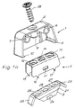
- Fig. 1a
- die Explosionsdarstellung einer ersten Ausführungsform eines Möbelkantenbeschlages mit zweiteiligem Sockel,
- Fig. 1b
- den Möbelkantenbeschlag gemäß Fig. 1a mit verbundenen Sockelteilen,
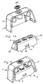
- Fig. 1c
- den Möbelkantenbeschlag gemäß Fig. 1a in Montagelage,
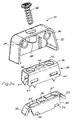
- Fig. 2a
- die Explosionsdarstellung einer zweiten Ausführungsform eines Möbelkantenbeschlages mit zweiteiligem Sockel,
- Fig. 2b
- den Möbelkantenbeschlag gemäß Fig. 2a mit verbundenen Sockelteilen und
- Fig. 2c
- den Möbelkantenbeschlag gemäß Fig. 2a in Montagelage.
- Fig. 1a
- the exploded view of a first embodiment of a furniture edge fitting with a two-part base,
- Fig. 1b
- the furniture edge fitting according to FIG. 1a with connected base parts,
- Fig. 1c
- the furniture edge fitting according to FIG. 1a in the assembly position,
- Fig. 2a
- the exploded view of a second embodiment of a furniture edge fitting with a two-part base,
- Fig. 2b
- the furniture edge fitting according to FIG. 2a with connected base parts and
- Fig. 2c
- the furniture edge fitting according to Fig. 2a in the assembly position.
In den Fign. 1a bis 1c ist ein Beschlag 1 dargestellt, der aus einem Gehäuse 2 sowie einem Sockel 3 besteht. Der Sockel 3 setzt sich zusammen aus einem als Halteteil dienenden Halteprofil 4 sowie einem Rastteil 5. Das Gehäuse 2 des dargestellten Beschlages 1 besteht ebenso wie das Rastteil 5 aus Kunststoff; das Halteprofil 4 ist aus Blech gefertigt.In Figs. 1a to 1c, a fitting 1 is shown, which consists of a
Das Gehäuse 2 ist nach zwei Seiten offen und trägt an seinen Innenwandungen Gewindehülsen 6, 7, 8. An die Flanken des Gehäuses 2 sind Raststege 9, 10 angeformt.The
Das Halteprofil 4 des Sockels 3 besitzt einen U-förmigen Querschnitt. An den Schenkelflächen des Halteprofils 4 sind Rastöffnungen 11 vorgesehen, von denen in den Fign. 1a bis 1c aufgrund der gewählten Perspektive lediglich eine Rastöffnung erkennbar ist. Die die Schenkelflächen verbindende Stegfläche des Halteprofils 4 weist Montagebohrungen 12, 13, 14 auf. An die der Stegfläche abgewandten Seiten der Schenkelflächen sind jeweils zwei Klauen angeformt, von denen in den Fign. 1a bis 1c drei Klauen 15, 16, 17 gezeigt sind.The holding
Das Rastteil 5 des Sockels 3 besitzt einen Grundkörper 21 sowie daran seitlich angeordnete Rastarme 22, 23. Auch der Grundkörper 21 des Rastteils 5 besitzt einen U-förmigen Querschnitt. An die trapezförmigen Schenkelflächen des Grundkörpers 21 ist jeweils eine Rastnase 24 angeformt. Die Stegfläche des Grundkörpers 21 weist drei Montagebohrungen 25, 26, 27 auf.The locking
Wie die Fign. 1a bis 1c zeigen, wird bei der Montage zunächst das Halteprofil 4 auf das Rastteil 5 aufgeschoben. Dabei rastet das Rastteil 5 mit seinen Rastnasen 24 in die dafür vorgesehenen Rastöffnungen 11 des Halteprofils 4 ein. In Einrastlage umgreift das Halteprofil 4 das Rastteil 5 an den Schenkelflächen sowie an der Stegfläche. Die Montagebohrungen 12, 13, 14 des Halteprofils 4 sind in dieser Lage fluchtend mit den jeweils zugeordneten Montagebohrungen 25, 26, 27 des Rastteils 5 angeordnet. Die Rastarme 22, 23 des Rastteils 5 überragen das Halteprofil 4 seitlich.As the fig. 1a to 1c show, the mounting
Nach dem Verrasten von Halteprofil 4 und Rastteil 5 wird der gesamte Sockel 3 auf die diesem zugeordnete, nicht dargestellte Möbelplatte aufgesetzt, ausgerichtet und durch die Montagebohrungen 12, 25 und 13, 27 mit der Möbelplatte verschraubt. Beim Festdrehen der Befestigungsschrauben gräbt sich der Sockel 3 mit den Klauen 15, 16, 17 in die Möbelplatte ein und wird so gegen Verschieben parallel zur Oberfläche der Möbelplatte gesichert. Die den Sockel 3 mit der Möbelplatte verbindenden Befestigungsschrauben dienen gleichzeitig als zusätzliche Verbindungselemente zwischen dem Rastteil 5 und dem Halteprofil 4.After the holding
Das Gehäuse 2 wird über die Gewindehülsen 6, 7, 8 mit der ihm zugeordneten, ebenfalls nicht dargestellten Möbelplatte verschraubt. Anschließend werden die beiden miteinander zu verbindenden Möbelplatten entsprechend der gewünschten Einbaulage aneinander angesetzt. Dabei wird das Gehäuse 2 über den Sockel 3 gestülpt. Beim Aufstülpen des Gehäuses 2 läuft dieses zunächst mit seinen Raststegen 9, 10 auf die Rastarme 22, 23 des Sockels 3 auf. Die Rastarme 22, 23 geben unter der Wirkung der aufschiebenden Druckkraft nach und werden in Richtung auf die dem Sockel 3 zugeordnete Möbelplatte verschwenkt. Infolgedessen können die Raststege 9, 10 die Rastarme 22, 23 passieren. Sobald die Raststege 9, 10 an den Rastarmen 22, 23 vorbeigeschoben worden sind, schwenken diese aufgrund ihrer Elastizität wieder in Richtung auf ihre ursprüngliche Lage zurück. Dabei beaufschlagen sie die Innenwandung des Gehäuses 2 an dessen Flanken und sorgen dadurch für eine Zentrierung des Gehäuses 2 gegenüber dem Sockel 3. Gleichzeitig hintergreifen die Rastarme 22, 23 die Raststege 9, 10 des Gehäuses 2 und schaffen somit eine vorläufige formschlüssige Verbindung zwischen dem Gehäuse 2 und dem Sockel 3 in einer Richtung senkrecht zu der dem Sockel 3 zugeordneten Möbelplatte. In dieser Richtung kann das Gehäuse 2 nur noch gegen den Widerstand der Rastarme 22, 23 von dem Sockel 3 abgezogen werden. Zur endgültigen Verbindung des Gehäuses 2 mit dem Sockel 3 dient eine Befestigungsschraube 28, die durch die Gewindehülse 8 des Gehäuses 2 in die Montagebohrungen 14, 26 des Sockels 3 eingedreht wird und dabei eine feste, aber lösbare Verbindung zwischen den betreffenden Möbelplatten herstellt.The
Die Fign. 2a bis 2c zeigen einen Beschlag 31, der hinsichtlich seines Aufbaus mit dem Beschlag 1 der Fign. 2a bis 2c grundsätzlich übereinstimmt. Auch der Beschlag 31 dient der Verbindung nicht dargestellter, rechtwinklig aneinanderstoßender Möbelplatten. Dabei ist eine Möbelplatte einem Gehäuse 32, die andere Möbelplatte einem Sockel 33 zugeordnet.The figures 2a to 2c show a fitting 31 which, with regard to its structure, is fitted with fitting 1 of FIGS. 2a to 2c basically coincides. The fitting 31 also serves to connect furniture panels, not shown, which abut one another at right angles. One furniture plate is assigned to a
Ein wesentlicher Unterschied zu dem Beschlag 1 der Fign. 1a bis 1c ergibt sich bei dem Beschlag 31 der Fign. 2a bis 2c im Hinblick auf die konstruktive Gestaltung des Sockels 33. Die Funktionselemente des Sockels 33, ein als Halteteil dienendes Halteprofil 34 sowie ein damit verrastbares Rastteil 35 sind nämlich in Verraststellung relativ zueinander verschiebbar. Diese Relativbeweglichkeit des Halteprofils 34 und des Rastteils 35 wird durch entsprechende Dimensionierung von in den Schenkelflächen des Halteprofils 34 angeordneten Rastöffnungen 41 und von in die Rastöffnungen 41 eingreifenden Rastnasen 54 erreicht. Wie insbesondere Fig. 2b zu entnehmen ist, umschließen die Rastöffnungen 41 die Rastnasen 54 in Verraststellung von Halteprofil 34 und Rastteil 35 nicht formschlüssig sondern vielmehr mit Spiel parallel zu der Oberfläche der dem Sockel 33 zugeordneten Möbelplatte. Gleichzeitig sind in der Stegfläche des Rastteils 35 benachbart zu einer Montagebohrung 56 Langlöcher 55, 57 vorgesehen. Die Stegfläche des Halteprofils 34 weist zwischen Montagebohrungen 42, 43 ein Langloch 44 auf.An essential difference to the fitting 1 of the FIGS. 1a to 1c results from the fitting 31 in FIGS. 2a to 2c with regard to the structural design of the
Zur Verbindung der aneinanderstoßenden Möbelplatten wird zunächst das Halteprofil 34 auf das Rastteil 35 aufgeschoben. Dabei rasten die Rastnasen 54 des Rastteils 35 in den Rastöffnungen 41 des Halteprofils 34 ein und werden in dieser Lage mit Spiel in Längsrichtung der Rastöffnungen 41 gehalten. Anschließend wird der Sockel 33 auf die diesem zugeordnete Möbelplatte aufgesetzt, ausgerichtet und durch die Montagebohrungen 42, 43 des Halteprofils 34 mit der Möbelplatte verschraubt. Die Befestigungsschrauben, mittels derer der Sockel 33 an der betreffenden Möbelplatte gehalten wird, durchdringen auch die Langlöcher 55, 57 des Rastteils 35, ohne sich jedoch mit deren Wandungen im Eingriff zu befinden. Infolgedessen läßt sich das Rastteil 35 auch nach Verschrauben des Sockels 33 mit der zugeordneten Möbelplatte in Längsrichtung der Rastöffnungen 41 relativ zu dem Halteprofil 34 verschieben.To connect the abutting furniture panels, the holding
Das Gehäuse 32 wird über Gewindehülsen 36, 37 mit der zugeordneten Möbelplatte verschraubt.The
Nachdem nun die beiden Beschlaghälften mit den zugeordneten Möbelplatten fest verbunden sind, werden diese der Montagelage entsprechend aneinander angesetzt. Dabei wird das Gehäuse 32 auf den Sockel 33 aufgeschoben und mit diesem, wie vorstehend für den Beschlag 1 der Fign. 1a bis 1c beschrieben, verrastet. In der Verraststellung des Gehäuses 32 und des Sockels 33 stützt sich der Sockel 33 über Rastarme 52, 53 an den Flanken der Innenwandung des Gehäuses 32 ab. Da das Gehäuse 32 das Halteprofil 34 in Montagelage mit Spiel überdeckt und da das Rastteil 35 mittels einer Langlochführung mit Spiel an dem Halteprofil 34 gehalten wird, ergibt sich eine Beweglichkeit des Gehäuses 32 relativ zu dem mit der betreffenden Möbelplatte fest verbundenen Halteprofil 34. Die durch das Verrasten des Gehäuses 32 mit dem Sockel 33 vorläufig miteinander verbundenen Möbelplatten können infolgedessen gegeneinander verschoben werden. Auf diese Art und Weise lassen sich die Möbelplatten so anordnen, daß ihre Kanten bündig miteinander abschließen.Now that the two fitting halves are firmly connected to the assigned furniture panels, they are attached to one another according to the mounting position. The
Zur endgültigen Verbindung der beiden Möbelplatten dient eine Befestigungsschraube 58, die durch eine Gewindehülse 38 an dem Gehäuse 32 in die Montagebohrung 56 des Rastteils 35 eingedreht wird. Unter der Wirkung der bei festgedrehter Befestigungsschraube 58 wirksamen Befestigungskraft in Schraubenlängsrichtung wird das Rastteil 35 an die Unterseite der Stegfläche des Halteprofils 34 gepreßt und an dieser reibschlüssig gehalten. Die Geometrie des Langloches 44 erlaubt vor der endgültigen Fixierung ein Verschieben des Gehäuses 32 mit dem über die Befestigungsschraube 58 damit verbundenen Rastteil 35 relativ zu dem fest mit der zugeordneten Möbelplatte verbundenen Halteprofil 34.For the final connection of the two furniture panels, a
Claims (11)
Applications Claiming Priority (2)
| Application Number | Priority Date | Filing Date | Title |
|---|---|---|---|
| DE9316140U | 1993-10-22 | ||
| DE9316140U DE9316140U1 (en) | 1993-10-22 | 1993-10-22 | Fitting for connecting abutting construction elements |
Publications (1)
| Publication Number | Publication Date |
|---|---|
| EP0653569A1 true EP0653569A1 (en) | 1995-05-17 |
Family
ID=6899752
Family Applications (1)
| Application Number | Title | Priority Date | Filing Date |
|---|---|---|---|
| EP94115247A Withdrawn EP0653569A1 (en) | 1993-10-22 | 1994-09-28 | Mounting for connecting abutting structural members |
Country Status (2)
| Country | Link |
|---|---|
| EP (1) | EP0653569A1 (en) |
| DE (1) | DE9316140U1 (en) |
Cited By (1)
| Publication number | Priority date | Publication date | Assignee | Title |
|---|---|---|---|---|
| EP2020513A1 (en) * | 2007-08-02 | 2009-02-04 | Hettich-Heinze GmbH & Co. KG | Fitting for connecting two furniture boards |
Citations (2)
| Publication number | Priority date | Publication date | Assignee | Title |
|---|---|---|---|---|
| FR1299833A (en) * | 1961-07-25 | 1962-07-27 | Assembly fitting with progressive locking by sliding elements for furniture or other uses | |
| DE9105568U1 (en) * | 1991-05-04 | 1991-06-13 | Haefele Kg, 7270 Nagold, De |
-
1993
- 1993-10-22 DE DE9316140U patent/DE9316140U1/en not_active Expired - Lifetime
-
1994
- 1994-09-28 EP EP94115247A patent/EP0653569A1/en not_active Withdrawn
Patent Citations (2)
| Publication number | Priority date | Publication date | Assignee | Title |
|---|---|---|---|---|
| FR1299833A (en) * | 1961-07-25 | 1962-07-27 | Assembly fitting with progressive locking by sliding elements for furniture or other uses | |
| DE9105568U1 (en) * | 1991-05-04 | 1991-06-13 | Haefele Kg, 7270 Nagold, De |
Cited By (1)
| Publication number | Priority date | Publication date | Assignee | Title |
|---|---|---|---|---|
| EP2020513A1 (en) * | 2007-08-02 | 2009-02-04 | Hettich-Heinze GmbH & Co. KG | Fitting for connecting two furniture boards |
Also Published As
| Publication number | Publication date |
|---|---|
| DE9316140U1 (en) | 1994-01-05 |
Similar Documents
| Publication | Publication Date | Title |
|---|---|---|
| DE102017117002A1 (en) | Device for fastening a component to a carrier component | |
| EP0735283A2 (en) | Fastener | |
| DE3039499C2 (en) | ||
| DE3912135C2 (en) | ||
| DE3214528C2 (en) | Device for fixing instrument housings in a carrier plate | |
| WO2007087829A1 (en) | System for separating off regions of a room | |
| DE19837367C2 (en) | Frame profile for a control cabinet | |
| EP0127030A2 (en) | Corner joint | |
| WO2015127924A1 (en) | Switch cabinet | |
| EP3692611B1 (en) | Arrangement for positioning a flat part on an electrical cabinet frame and related method | |
| EP0223106B1 (en) | Frame construction | |
| EP0067970B1 (en) | Fastening device for facing elements on outer wall | |
| EP2105065A1 (en) | Furniture body | |
| CH652269A5 (en) | Quick mounting base made of plastic, for fixing an electrical device or printed-circuit board | |
| DE202018106711U1 (en) | Profile system | |
| EP0459987B1 (en) | Twin-shell housing for appliances | |
| EP0653569A1 (en) | Mounting for connecting abutting structural members | |
| EP3797226B1 (en) | Fastening arrangement | |
| DE102013100308A1 (en) | Bar fitting for a window or a door | |
| DE19614942B4 (en) | Profile connection for mitred profiles | |
| DE3500258A1 (en) | Grid ceiling, in particular clean-room grid ceiling | |
| DE4409155A1 (en) | Connecting element for connecting panel-like wall elements | |
| EP0903063B1 (en) | Housing | |
| DE102005013086B4 (en) | System consisting of a plinth panel and a cover | |
| DE102004059419B4 (en) | device housing |
Legal Events
| Date | Code | Title | Description |
|---|---|---|---|
| PUAI | Public reference made under article 153(3) epc to a published international application that has entered the european phase |
Free format text: ORIGINAL CODE: 0009012 |
|
| AK | Designated contracting states |
Kind code of ref document: A1 Designated state(s): AT BE CH DE DK ES FR GB GR IE IT LI LU MC NL PT SE |
|
| 17P | Request for examination filed |
Effective date: 19950331 |
|
| GRAG | Despatch of communication of intention to grant |
Free format text: ORIGINAL CODE: EPIDOS AGRA |
|
| 17Q | First examination report despatched |
Effective date: 19960507 |
|
| GRAH | Despatch of communication of intention to grant a patent |
Free format text: ORIGINAL CODE: EPIDOS IGRA |
|
| STAA | Information on the status of an ep patent application or granted ep patent |
Free format text: STATUS: THE APPLICATION IS DEEMED TO BE WITHDRAWN |
|
| 18D | Application deemed to be withdrawn |
Effective date: 19961009 |