EP0653340A1 - Procedure for controlling braking in vehicles - Google Patents
Procedure for controlling braking in vehicles Download PDFInfo
- Publication number
- EP0653340A1 EP0653340A1 EP94117304A EP94117304A EP0653340A1 EP 0653340 A1 EP0653340 A1 EP 0653340A1 EP 94117304 A EP94117304 A EP 94117304A EP 94117304 A EP94117304 A EP 94117304A EP 0653340 A1 EP0653340 A1 EP 0653340A1
- Authority
- EP
- European Patent Office
- Prior art keywords
- braking
- braking process
- wheel speed
- threshold value
- axle
- Prior art date
- Legal status (The legal status is an assumption and is not a legal conclusion. Google has not performed a legal analysis and makes no representation as to the accuracy of the status listed.)
- Granted
Links
- 238000000034 method Methods 0.000 title claims abstract description 41
- 238000011156 evaluation Methods 0.000 claims abstract description 7
- 230000001419 dependent effect Effects 0.000 claims abstract description 6
- 230000001105 regulatory effect Effects 0.000 claims abstract 5
- 230000001276 controlling effect Effects 0.000 claims abstract 2
- 238000005096 rolling process Methods 0.000 claims description 3
- 230000005484 gravity Effects 0.000 claims 1
- 238000011161 development Methods 0.000 description 3
- 230000018109 developmental process Effects 0.000 description 3
- 230000008878 coupling Effects 0.000 description 1
- 238000010168 coupling process Methods 0.000 description 1
- 238000005859 coupling reaction Methods 0.000 description 1
- 238000006073 displacement reaction Methods 0.000 description 1
- 230000001771 impaired effect Effects 0.000 description 1
- 238000005259 measurement Methods 0.000 description 1
- 210000002023 somite Anatomy 0.000 description 1
- 230000002123 temporal effect Effects 0.000 description 1
Images
Classifications
-
- B—PERFORMING OPERATIONS; TRANSPORTING
- B60—VEHICLES IN GENERAL
- B60T—VEHICLE BRAKE CONTROL SYSTEMS OR PARTS THEREOF; BRAKE CONTROL SYSTEMS OR PARTS THEREOF, IN GENERAL; ARRANGEMENT OF BRAKING ELEMENTS ON VEHICLES IN GENERAL; PORTABLE DEVICES FOR PREVENTING UNWANTED MOVEMENT OF VEHICLES; VEHICLE MODIFICATIONS TO FACILITATE COOLING OF BRAKES
- B60T8/00—Arrangements for adjusting wheel-braking force to meet varying vehicular or ground-surface conditions, e.g. limiting or varying distribution of braking force
- B60T8/17—Using electrical or electronic regulation means to control braking
- B60T8/1701—Braking or traction control means specially adapted for particular types of vehicles
- B60T8/1708—Braking or traction control means specially adapted for particular types of vehicles for lorries or tractor-trailer combinations
Definitions
- the dynamic axle load on the axles of a motor vehicle is an important parameter for assessing the braking process - particularly when the vehicle is loaded differently: the optimal braking force distribution between the different axles depends on it, and thus the maximum achievable braking force.
- motor vehicles especially those with a short wheelbase and high center of mass (for example, tractors on semi-trailer tractors or cars with roof loads) - major changes in the dynamic axle load occur during braking.
- the invention has for its object to provide a simple method for controlling the braking process of motor vehicles, in particular taking into account dynamic axle load changes.
- the method is explained in more detail below, for example a semi-trailer with tractor and trailer being assumed as the motor vehicle.
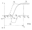
- the figure shows the time profile of the brake pressure p (towing vehicle p Z, semi-trailer p A ) and the time profile of the slip difference SD (between the front and rear axles of the towing vehicle).
- the start of braking of the trailer and the strength of the braking should be selected so that the towing vehicle or its front axle is relieved.
- the dynamic axle load change is determined by evaluating the temporal slip difference curve SD (the horizontal coupling force between the towing vehicle and the trailer generates a moment about the transverse axis of the towing vehicle, which results in a brief dynamic axle load change on the towing vehicle axles; this also changes the adhesion coefficient and according to the adhesion load Slip curve also the slip or the slip difference SD).
- At least one wheel on the tractor's axles is equipped with speed sensors to determine the wheel speeds n V (front axle) and n H (rear axle), the brake pressures p Z on the wheels of the tractor and the brake pressure p A for the trailer can be controlled electrically .
- a threshold value SW is specified for the slip difference SD between the front and rear axles of the towing vehicle (the slip difference SD depends on the wheel speed difference n V - n H ); this threshold value SW is significantly larger (for example a 3 to 4% change in the slip difference SD based on the rolling slip value before the braking process) than the slip difference which normally occurs during the braking process (for example a 2% change).
- the time difference between the start of the braking force development on the towing vehicle and the trailer can be determined and, depending on this, an improved braking of the semitrailer can be achieved by deliberately changing the braking force development: when determining the time t2 (reaching the threshold value SW) and the Time t D during which the threshold SD is exceeded (time interval between t2 and t4), the brake pressure on the towing vehicle and trailer (time of the start of braking t1, t3 and size of the brake pressures p Z , p A or the braking force distribution) varies accordingly and thereby the braking process can be optimized in terms of safety and braking distance.
Landscapes
- Engineering & Computer Science (AREA)
- Transportation (AREA)
- Mechanical Engineering (AREA)
- Regulating Braking Force (AREA)
Abstract
Description
Die dynamische Achslast auf die Achsen eines Kraftfahrzeugs ist für die Beurteilung des Bremsvorgangs - insbesondere bei unterschiedlichen Beladungszuständen des Kraftfahrzeugs - eine wichtige Größe: von ihr hängt die optimale Bremskraftverteilung zwischen den verschiedenen Achsen ab und damit auch die maximal erreichbare Bremskraft. Bei manchen Kraftfahrzeugen - insbesondere bei solchen mit kurzem Rad stand und hohen Masseschwerpunkten (beispielsweise Zugmaschinen von Sattelschlepperzügen oder PKWs mit Dachlast) - treten beim Bremsvorgang größere Änderungen der dynamischen Achslast auf. Dies hat zur Folge, daß sich der Schlupf der Räder während des Bremsvorgangs verändert, wodurch einerseits die Bremskrafteinstellung bzw. die Bremskraftverteilung und demzufolge auch der Bremsvorgang selbst nicht optimal ist (längerer Bremsweg), und andererseits die Gefahr des Blockierens einzelner Räder besteht, was die Sicherheit bzw. Fahrstabilität des Kraftfahrzeugs massiv beeinträchtigt.The dynamic axle load on the axles of a motor vehicle is an important parameter for assessing the braking process - particularly when the vehicle is loaded differently: the optimal braking force distribution between the different axles depends on it, and thus the maximum achievable braking force. In some motor vehicles - especially those with a short wheelbase and high center of mass (for example, tractors on semi-trailer tractors or cars with roof loads) - major changes in the dynamic axle load occur during braking. This has the consequence that the slip of the wheels changes during the braking process, whereby on the one hand the braking force setting or the braking force distribution and consequently the braking process itself is not optimal (longer braking distance), and on the other hand there is a risk of individual wheels locking, which is what Safety or driving stability of the motor vehicle massively impaired.
Der Erfindung liegt die Aufgabe zugrunde, ein einfaches Verfahren zur Regelung des Bremsvorgangs von Kraftfahrzeugen, insbesondere unter Berücksichtigung dynamischer Achslaständerungen anzugeben.The invention has for its object to provide a simple method for controlling the braking process of motor vehicles, in particular taking into account dynamic axle load changes.
Diese Aufgabe wird erfindungsgemäß durch die Merkmale im Kennzeichen des Patentanspruchs 1 gelöst. Vorteilhafte Weiterbildungen des Verfahrens ergeben sich aus den Unteransprüchen.This object is achieved by the features in the characterizing part of patent claim 1. Advantageous further developments of the method result from the subclaims.
Zur Regelung des Bremsvorgangs werden die Kraftfahrzeuge in verschiedene Klassen hinsichtlich des Verhaltens bzgl. dynamischer Achslaständerungen eingruppiert und abhängig von dieser Klassifizierung unterschiedliche Strategien zur Beeinflussung des Bremsvorgangs gewählt. Hierzu sind folgende Größen von Interesse:
- die Raddrehzahl nV mindestens eines Rades der Vorderachse; die Raddrehzahl nV wird über einen (meist bereits vorhandenen) Raddrehzahl-Sensor bestimmt,
- optional die Raddrehzahl nH mindestens eines Rades der Hinterachse als Referenzwert (Messung über Raddrehzahl-Sensor); hieraus kann die Schlupfdifferenz SD zwischen Vorderachse und Hinterachse bestimmt werden,
- der Zeitpunkt t₀ des Bremsbeginns; dieser wird entweder durch einen Bremsdrucksensor oder über einen Wegsensor am Bremspedal festgelegt,
- der Zeitablauf des Bremsvorgangs; hieraus kann die Zeitabhängigkeit der Raddrehzahlen nV(tB) bzw. nH(tB) während des Bremsvorgangs ermittelt werden,
- der Bremsdruck p an jeder Achse des Fahrzeugs, um den Bremsvorgang durch Vorgabe des Bremsdrucks steuern zu können.
- the wheel speed n V of at least one wheel of the front axle; the wheel speed n V is determined by a (usually already existing) wheel speed sensor,
- optionally the wheel speed n H of at least one wheel of the rear axle as a reference value (measurement via wheel speed sensor); from this the slip difference SD between the front axle and the rear axle can be determined,
- the time t₀ of the start of braking; this is determined either by a brake pressure sensor or via a displacement sensor on the brake pedal,
- the timing of the braking process; the time dependence of the wheel speeds n V (t B ) or n H (t B ) during the braking process can be determined from this,
- the brake pressure p on each axle of the vehicle in order to be able to control the braking process by specifying the brake pressure.
Der ermittelte zeitliche Verlauf der Raddrehzahl an der Vorderachse (oder - bei Kenntnis der Raddrehzahl der Hinterachse - der ermittelte zeitliche Verlauf der Schlupfdifferenz) wird ausgewertet und abhängig von dieser Auswertung die Klassifizierung der Kraftfahrzeuge vorgenommen. Insbesondere wird auf ein Auftreten signifikanter dynamischer Achslaständerungen dann geschlossen, wenn sich die Raddrehzahl (oder die Schlupfdifferenz) kurzzeitig (signifikant) ändert. Dieser Auswertung wird ein Zeitkriterium und ein Größenkriterium zugrundegelegt:
- Zeitkriterium: die Änderung der Raddrehzahl bzw. der Schlupfdifferenz muß innerhalb eines bestimmten Zeitfensters während des Bremsvorgangs auftreten (insbesondere zu Beginn des Bremsvorgangs, beispielsweise innerhalb 0,3 s nach Bremsbeginn); dieses Zeitfenster wird unabhängig von der Fahrzeuggeschwindigkeit oder von der Art des Bremsvorgangs vorgegeben.
- Größenkriterium: die Änderung der Raddrehzahl bzw. der Schlupfdifferenz muß einen bestimmten drehzahlabhängigen bzw. schlupfabhängigen Schwellwert überschreiten; dieser Schwellwert wird signifikant größer als die beim Bremsvorgang üblicherweise auftretenden Änderungswerte für den Schlupfwert (typischerweise 2 % Änderung) vorgegeben - der Rollschlupfwert vor dem Bremsvorgang dient hierbei als Ausgangsgröße. Durch die Vorgabe und Auswertung mehrerer unterschiedlicher Schwellwerte können genauere und detailliertere Aussagen gewonnen werden.
- Time criterion: the change in the wheel speed or the slip difference must occur within a certain time window during the braking process (in particular at the beginning of the braking process, for example within 0.3 s after the start of braking); this time window is specified regardless of the vehicle speed or the type of braking.
- Size criterion: the change in the wheel speed or the slip difference must exceed a certain speed-dependent or slip-dependent threshold value; this threshold value is set significantly greater than the change values for the slip value (typically 2% change) that usually occur during the braking operation - the rolling slip value before the braking operation serves as an output variable. By specifying and evaluating several different threshold values, more precise and detailed statements can be obtained.
Das vorgestellte Verfahren vereinigt mehrere Vorteile in sich:
- Es werden keine zusätzlichen Sensoren benötigt, so daß eine kostengünstige Realisierung möglich ist.
- Es ist sehr einfach und kann auf beliebigen Fahrzeugen mit elektrisch ansteuerbaren oder regelbaren Bremssystemen implementiert werden.
- Es liefert eine Entscheidung über die zu wählende Bremsstrategie: treten keine (signifikanten) dynamischen Achslaständerungen beim Bremsvorgang auf, ist von dieser Seite aus keine Änderung des Bremsverhaltens erforderlich; treten dagegen signifikante dynamische Achslaständerungen auf, kann durch Beeinflussung des Bremsvorgangs - beispielsweise durch Steuerung der Bremskraftverteilung (Vorderachse/Hinterachse bei einem Anhänger- oder Aufliegerfahrzeug) oder/und des Zeitpunkts des Bremsbeginns an der jeweiligen Achse (Vorderachse/Hinterachse) - der Bremsvorgang verbessert werden.
- Bei Kenntnis des Fahrzeugverhaltens bzgl. dynamischer Achslaständerungen kann der Bremsvorgang verbessert werden: die maximal einsetzbare Bremskraft kann vergrößert werden, es ist ein kürzerer Bremsweg erreichbar, es besteht keine Gefahr des Blockierens einzelner Räder - der Bremsprozeß wird somit insgesamt sicherer.
- No additional sensors are required, so that cost-effective implementation is possible.
- It is very simple and can be implemented on any vehicle with electrically controllable or adjustable braking systems.
- It provides a decision on the braking strategy to be selected: if there are no (significant) dynamic axle load changes during the braking process, no change in the braking behavior is required from this side; if, on the other hand, significant dynamic axle load changes occur, the braking process can be improved by influencing the braking process - for example, by controlling the braking force distribution (front axle / rear axle in a trailer or semi-trailer vehicle) and / or the time at which braking begins on the respective axle (front axle / rear axle) .
- If the vehicle behavior regarding dynamic axle load changes is known, the braking process can be improved: the maximum braking force that can be used can be increased, a shorter braking distance can be achieved, there is no risk of individual wheels locking - the braking process is thus generally safer.
Das Verfahren wird im folgenden näher erläutert, wobei als Kraftfahrzeug beispielsweise ein Sattelschlepper mit Zugmaschine und Auflieger angenommen wird. In der Figur ist hierzu der zeitliche Verlauf des Bremsdrucks p (Zugfahrzeug pZ, Auflieger pA) und der zeitliche Verlauf der Schlupfdifferenz SD (zwischen Vorderachse und Hinterachse des Zugfahrzeugs) dargestellt.The method is explained in more detail below, for example a semi-trailer with tractor and trailer being assumed as the motor vehicle. The figure shows the time profile of the brake pressure p (towing vehicle p Z, semi-trailer p A ) and the time profile of the slip difference SD (between the front and rear axles of the towing vehicle).
Anhand der zeitlichen Bremsdruckkurven p ist zu erkennen, daß beim Bremsvorgang Probleme auftreten: Bei der Abbremsung des Sattelschleppers (Bremsbeginn zum Zeitpunkt t₀) wird zunächst das Zugfahrzeug (Zugmaschine) abgebremst (Zeitpunkt t₁, Bremsdruck pZ), die Achslast auf die Vorderachse des Zugfahrzeugs durch das eingeleitete Moment des Aufliegers vergrößert und die Achslast auf die Hinterachse verkleinert; aufgrund des kurzen Radstands des Zugfahrzeugs wird die Vorderachse des Zugfahrzeugs dadurch sehr stark belastet. Sobald der Auflieger abgebremst wird (Zeitpunkt t₃, Bremsdruck pA), wird die Vorderachse zwar entlastet, der Sattelschlepper kann aber instabil werden. Zur Verbesserung des Bremsverhaltens sollten demnach Bremsbeginn des Aufliegers und Stärke der Abbremsung so gewählt werden, daß das Zugfahrzeug bzw. dessen Vorderachse entlastet wird.
Hierzu wird die dynamische Achslaständerung durch Auswertung der zeitlichen Schlupfdifferenzkurve SD ermittelt (die horizontale Koppelkraft zwischen Zugfahrzeug und Auflieger erzeugt ein Moment um die Querachse des Zugfahrzeugs, woraus eine kurze dynamische Achslaständerung an den Zugfahrzeugachsen resultiert; hierdurch ändert sich auch der Kraftschlußbeiwert und gemäß der Kraftschlußbeanspruchungs-Schlupf-Kurve auch der Schlupf bzw. die Schlupfdifferenz SD). Beim Sattelzug ist mindestens ein Rad an den Achsen der Zugmaschine zur Bestimmung der Raddrehzahlen nV (Vorderachse) und nH (Hinterachse) mit Drehzahlsensoren bestückt, die Bremsdrücke pZ an den Rädern der Zugmaschine und der Bremsdruck pA für den Auflieger sind elektrisch ansteuerbar. Der Zeitpunkt t₀ des Bremsbeginns wird beispielsweise durch eine in einem der Bremszylinder angebrachte Druckdose ermittelt; zwischen t₀ = 0 s und t₆ = 0,6 s wird ein Zeitfenster tF vorgegeben, während dem eine Auswertung vorgenommen wird (Zeitkriterium). Zur Auswertung wird ein Schwellwert SW für die Schlupfdifferenz SD zwischen Vorderachse und Hinterachse des Zugfahrzeugs vorgegeben (die Schlupfdifferenz SD ist abhängig von der Raddrehzahldifferenz nV - nH); dieser Schwellwert SW ist signifikant größer (beispielsweise 3 bis 4 % Änderung der Schlupfdifferenz SD bezogen auf den Rollschlupfwert vor dem Bremsvorgang) als die normalerweise während des Bremsvorgangs auftretende Schlupfdifferenz (beispielsweise 2 % Änderung).
Durch die Auswertung der zeitlichen Schlupfdifferenzkurve kann zunächst ermittelt werden, ob beim Bremsvorgang des Sattelschleppers eine signifikante Änderung der dynamischen Achslast auftritt (Erreichen bzw. Überschreiten des Schwellwerts SW). Ist dies der Fall, kann die Zeitdifferenz zwischen dem Beginn der Bremskraftentfaltung am Zugfahrzeug und am Auflieger bestimmt werden und abhängig davon durch gezielte Veränderung der zeitlichen Bremskraftentfaltung eine verbesserte Abbremsung des Sattelzugs erreicht werden: bei Ermittlung des Zeitpunkts t₂ (Erreichen des Schwellwerts SW) und der Zeitdauer tD während der der Schwellwert SD überschritten wird (Zeitintervall zwischen t₂ und t₄), kann der Bremsdruck an Zugfahrzeug und Auflieger (Zeitpunkt der Bremsbeginne t₁, t₃ und Größe der Bremsdrücke pZ, pA bzw. der Bremskraftverteilung) entsprechend variiert und dadurch der Bremsvorgang im Hinblick auf Sicherheit und Bremsweg optimiert werden.On the basis of the time brake pressure curves p it can be seen that problems occur when braking: When braking the semitrailer (start of braking at time t₀), the towing vehicle (tractor) is first braked (time t₁, braking pressure p Z ), the axle load on the front axle of the towing vehicle increased by the moment of the trailer initiated and the axle load reduced to the rear axle; Due to the short wheelbase of the towing vehicle, the front axle of the towing vehicle is very heavily loaded. As soon as the trailer is braked (time t₃, brake pressure p A ), the front axle is relieved, but the tractor can become unstable. To improve the braking behavior, the start of braking of the trailer and the strength of the braking should be selected so that the towing vehicle or its front axle is relieved.
For this purpose, the dynamic axle load change is determined by evaluating the temporal slip difference curve SD (the horizontal coupling force between the towing vehicle and the trailer generates a moment about the transverse axis of the towing vehicle, which results in a brief dynamic axle load change on the towing vehicle axles; this also changes the adhesion coefficient and according to the adhesion load Slip curve also the slip or the slip difference SD). At least one wheel on the tractor's axles is equipped with speed sensors to determine the wheel speeds n V (front axle) and n H (rear axle), the brake pressures p Z on the wheels of the tractor and the brake pressure p A for the trailer can be controlled electrically . The point in time t Brems of the beginning of braking is determined, for example, by a pressure cell fitted in one of the brake cylinders; Between t₀ = 0 s and t₆ = 0.6 s, a time window t F is specified during which an evaluation is carried out (time criterion). For Evaluation, a threshold value SW is specified for the slip difference SD between the front and rear axles of the towing vehicle (the slip difference SD depends on the wheel speed difference n V - n H ); this threshold value SW is significantly larger (for example a 3 to 4% change in the slip difference SD based on the rolling slip value before the braking process) than the slip difference which normally occurs during the braking process (for example a 2% change).
By evaluating the slip difference curve over time, it can first be determined whether a significant change in the dynamic axle load occurs when the semi-trailer truck brakes (reaching or exceeding the threshold value SW). If this is the case, the time difference between the start of the braking force development on the towing vehicle and the trailer can be determined and, depending on this, an improved braking of the semitrailer can be achieved by deliberately changing the braking force development: when determining the time t₂ (reaching the threshold value SW) and the Time t D during which the threshold SD is exceeded (time interval between t₂ and t₄), the brake pressure on the towing vehicle and trailer (time of the start of braking t₁, t₃ and size of the brake pressures p Z , p A or the braking force distribution) varies accordingly and thereby the braking process can be optimized in terms of safety and braking distance.
Claims (7)
Applications Claiming Priority (2)
| Application Number | Priority Date | Filing Date | Title |
|---|---|---|---|
| DE4338542 | 1993-11-11 | ||
| DE4338542A DE4338542C2 (en) | 1993-11-11 | 1993-11-11 | Method for controlling the braking process of motor vehicles |
Publications (2)
| Publication Number | Publication Date |
|---|---|
| EP0653340A1 true EP0653340A1 (en) | 1995-05-17 |
| EP0653340B1 EP0653340B1 (en) | 1997-03-12 |
Family
ID=6502372
Family Applications (1)
| Application Number | Title | Priority Date | Filing Date |
|---|---|---|---|
| EP94117304A Expired - Lifetime EP0653340B1 (en) | 1993-11-11 | 1994-11-03 | Procedure for controlling braking in vehicles |
Country Status (2)
| Country | Link |
|---|---|
| EP (1) | EP0653340B1 (en) |
| DE (2) | DE4338542C2 (en) |
Cited By (2)
| Publication number | Priority date | Publication date | Assignee | Title |
|---|---|---|---|---|
| WO2007008150A1 (en) | 2005-07-11 | 2007-01-18 | Volvo Lastvagnar Ab | A system and a method for stabilising a vehicle combination |
| GB2462864A (en) * | 2008-08-23 | 2010-02-24 | Haldex Brake Products Ltd | Method of and Apparatus for Monitoring the Performance of a Vehicle Braking System |
Families Citing this family (4)
| Publication number | Priority date | Publication date | Assignee | Title |
|---|---|---|---|---|
| DE19530735A1 (en) * | 1995-08-22 | 1997-02-27 | Bosch Gmbh Robert | Method and device for controlling the brake system of a vehicle |
| DE19536058A1 (en) * | 1995-09-28 | 1997-04-03 | Teves Gmbh Alfred | Improvement of the control behavior of an anti-lock brake system |
| JP4440459B2 (en) | 1997-11-20 | 2010-03-24 | コンティネンタル・テーベス・アクチエンゲゼルシヤフト・ウント・コンパニー・オッフェネ・ハンデルスゲゼルシヤフト | Method and apparatus for controlling or adjusting braking force distribution |
| DE19953413A1 (en) * | 1999-11-06 | 2001-02-08 | Daimler Chrysler Ag | Driving a towing vehicle and a single-axle trailer uses a steering wheel sensor to operate the trailer wheel brakes according to the direction of steering movements for improved driving conditions and safety |
Citations (5)
| Publication number | Priority date | Publication date | Assignee | Title |
|---|---|---|---|---|
| WO1985002590A1 (en) * | 1983-12-16 | 1985-06-20 | Robert Bosch Gmbh | Process for detecting the desired braking moment for the different wheels of a vehicle |
| EP0173954A2 (en) * | 1984-09-07 | 1986-03-12 | Robert Bosch Gmbh | Brake pressure regulation process |
| DE3840564A1 (en) * | 1988-12-01 | 1990-03-08 | Daimler Benz Ag | Method for controlling the brake pressure in a motor vehicle as a function of the load |
| EP0445575A2 (en) * | 1990-03-08 | 1991-09-11 | Mercedes-Benz Ag | Brake pressure distribution procedure between the axes of an automobile vehicle, provided with anti-skid pressurized fluid brake |
| WO1993007037A1 (en) * | 1991-10-04 | 1993-04-15 | Caterpillar Inc. | Method and apparatus for controlling differentially driven wheel slip for an articulated vehicle |
Family Cites Families (2)
| Publication number | Priority date | Publication date | Assignee | Title |
|---|---|---|---|---|
| DE4130848C1 (en) * | 1991-09-17 | 1993-03-18 | Mercedes-Benz Aktiengesellschaft, 7000 Stuttgart, De | |
| DE4200440A1 (en) * | 1992-01-10 | 1993-07-15 | Bayerische Motoren Werke Ag | METHOD FOR THE BRAKING CONTROL OF MOTOR SPRINGS |
-
1993
- 1993-11-11 DE DE4338542A patent/DE4338542C2/en not_active Expired - Lifetime
-
1994
- 1994-11-03 DE DE59402048T patent/DE59402048D1/en not_active Expired - Fee Related
- 1994-11-03 EP EP94117304A patent/EP0653340B1/en not_active Expired - Lifetime
Patent Citations (5)
| Publication number | Priority date | Publication date | Assignee | Title |
|---|---|---|---|---|
| WO1985002590A1 (en) * | 1983-12-16 | 1985-06-20 | Robert Bosch Gmbh | Process for detecting the desired braking moment for the different wheels of a vehicle |
| EP0173954A2 (en) * | 1984-09-07 | 1986-03-12 | Robert Bosch Gmbh | Brake pressure regulation process |
| DE3840564A1 (en) * | 1988-12-01 | 1990-03-08 | Daimler Benz Ag | Method for controlling the brake pressure in a motor vehicle as a function of the load |
| EP0445575A2 (en) * | 1990-03-08 | 1991-09-11 | Mercedes-Benz Ag | Brake pressure distribution procedure between the axes of an automobile vehicle, provided with anti-skid pressurized fluid brake |
| WO1993007037A1 (en) * | 1991-10-04 | 1993-04-15 | Caterpillar Inc. | Method and apparatus for controlling differentially driven wheel slip for an articulated vehicle |
Cited By (7)
| Publication number | Priority date | Publication date | Assignee | Title |
|---|---|---|---|---|
| WO2007008150A1 (en) | 2005-07-11 | 2007-01-18 | Volvo Lastvagnar Ab | A system and a method for stabilising a vehicle combination |
| EP1904351A1 (en) * | 2005-07-11 | 2008-04-02 | Volvo Lastvagnar Ab | A system and a method for stabilising a vehicle combination |
| EP1904351A4 (en) * | 2005-07-11 | 2010-09-15 | Volvo Lastvagnar Ab | A system and a method for stabilising a vehicle combination |
| EP1904351B1 (en) | 2005-07-11 | 2016-03-30 | Volvo Lastvagnar Ab | A system and a method for stabilising a vehicle combination |
| GB2462864A (en) * | 2008-08-23 | 2010-02-24 | Haldex Brake Products Ltd | Method of and Apparatus for Monitoring the Performance of a Vehicle Braking System |
| WO2010023426A3 (en) * | 2008-08-23 | 2010-09-02 | Haldex Brake Products Limited | Method of and apparatus for monitoring the performance of a vehicle braking system |
| GB2462864B (en) * | 2008-08-23 | 2012-05-23 | Haldex Brake Products Ltd | Method of and apparatus for monitoring the performance of a vehicle braking system |
Also Published As
| Publication number | Publication date |
|---|---|
| DE59402048D1 (en) | 1997-04-17 |
| EP0653340B1 (en) | 1997-03-12 |
| DE4338542C2 (en) | 1997-07-24 |
| DE4338542A1 (en) | 1995-05-18 |
Similar Documents
| Publication | Publication Date | Title |
|---|---|---|
| EP1107893B1 (en) | Method and device for stabilizing a vehicle | |
| EP0832017B1 (en) | Method of control for improving the behaviour of an anti-lock system | |
| DE4438252C2 (en) | Method and device for electronically controlling the brake system of a vehicle | |
| EP0697314B1 (en) | Method for load dependant brake pressure control of a tractor-trailer combination | |
| EP1414684B1 (en) | Braking system for trailers of utility vehicles | |
| DE19744066A1 (en) | Recognition procedure for trailer operation for cars | |
| EP0954460A1 (en) | Method and device for detecting motor vehicle tilt | |
| DE19619381A1 (en) | Yaw moment mitigation method in an anti-lock braking system | |
| DE10149190A1 (en) | Rolling movement control apparatus for motor vehicle, has brake force controller to control braking force of each wheel based on calculated controlling variables for attaining target rolling angle of vehicle | |
| DE102010026411A1 (en) | Method and device for carrying out a brake test on trailer and / or semitrailer vehicles | |
| DE19751839A1 (en) | Tilt tendency detection in vehicle | |
| DE19859953A1 (en) | Device and method for stabilizing a vehicle combination consisting of a towing vehicle and a trailer or semitrailer | |
| EP0844155B1 (en) | Yaw rate reduction procedure in a vehicle with an anti-lock bracking system | |
| DE4136571C1 (en) | ||
| DE19719466B4 (en) | Brake force control system for a motor vehicle | |
| DE19545001B4 (en) | Method for yaw moment attenuation in an anti-lock braking system | |
| EP1439103B1 (en) | Vehicle dynamics control method for a tractor-trailer combination | |
| EP2049372B1 (en) | Method for brake pressure distribution between the axles of a vehicle | |
| DE102013017407A1 (en) | Method for checking a loading state of a semitrailer or trailer of a utility vehicle | |
| DE19739825B4 (en) | Method and device for controlling the brake system of a vehicle | |
| EP0653340B1 (en) | Procedure for controlling braking in vehicles | |
| EP0844954B1 (en) | Method and device for controlling a vehicle brake system | |
| DE19633834B4 (en) | Method and device for controlling the brake system of a vehicle | |
| DE19944333B4 (en) | Device for controlling a yawing moment | |
| DE19618624C1 (en) | Device for evaluation of signals from sensor |
Legal Events
| Date | Code | Title | Description |
|---|---|---|---|
| PUAI | Public reference made under article 153(3) epc to a published international application that has entered the european phase |
Free format text: ORIGINAL CODE: 0009012 |
|
| AK | Designated contracting states |
Kind code of ref document: A1 Designated state(s): DE FR GB IT SE |
|
| 17P | Request for examination filed |
Effective date: 19950512 |
|
| 17Q | First examination report despatched |
Effective date: 19960522 |
|
| GRAG | Despatch of communication of intention to grant |
Free format text: ORIGINAL CODE: EPIDOS AGRA |
|
| GRAH | Despatch of communication of intention to grant a patent |
Free format text: ORIGINAL CODE: EPIDOS IGRA |
|
| GRAH | Despatch of communication of intention to grant a patent |
Free format text: ORIGINAL CODE: EPIDOS IGRA |
|
| GRAA | (expected) grant |
Free format text: ORIGINAL CODE: 0009210 |
|
| ITF | It: translation for a ep patent filed | ||
| AK | Designated contracting states |
Kind code of ref document: B1 Designated state(s): DE FR GB IT SE |
|
| GBT | Gb: translation of ep patent filed (gb section 77(6)(a)/1977) |
Effective date: 19970313 |
|
| REF | Corresponds to: |
Ref document number: 59402048 Country of ref document: DE Date of ref document: 19970417 |
|
| ET | Fr: translation filed | ||
| RAP2 | Party data changed (patent owner data changed or rights of a patent transferred) |
Owner name: DAIMLER-BENZ AKTIENGESELLSCHAFT Owner name: TEMIC TELEFUNKEN MICROELECTRONIC GMBH |
|
| PLBE | No opposition filed within time limit |
Free format text: ORIGINAL CODE: 0009261 |
|
| STAA | Information on the status of an ep patent application or granted ep patent |
Free format text: STATUS: NO OPPOSITION FILED WITHIN TIME LIMIT |
|
| 26N | No opposition filed | ||
| REG | Reference to a national code |
Ref country code: GB Ref legal event code: 732E |
|
| REG | Reference to a national code |
Ref country code: GB Ref legal event code: 732E |
|
| PGFP | Annual fee paid to national office [announced via postgrant information from national office to epo] |
Ref country code: GB Payment date: 19991027 Year of fee payment: 6 |
|
| PGFP | Annual fee paid to national office [announced via postgrant information from national office to epo] |
Ref country code: FR Payment date: 19991123 Year of fee payment: 6 |
|
| PGFP | Annual fee paid to national office [announced via postgrant information from national office to epo] |
Ref country code: SE Payment date: 19991124 Year of fee payment: 6 |
|
| PGFP | Annual fee paid to national office [announced via postgrant information from national office to epo] |
Ref country code: DE Payment date: 20000202 Year of fee payment: 6 |
|
| PG25 | Lapsed in a contracting state [announced via postgrant information from national office to epo] |
Ref country code: GB Free format text: LAPSE BECAUSE OF NON-PAYMENT OF DUE FEES Effective date: 20001103 |
|
| PG25 | Lapsed in a contracting state [announced via postgrant information from national office to epo] |
Ref country code: SE Free format text: THE PATENT HAS BEEN ANNULLED BY A DECISION OF A NATIONAL AUTHORITY Effective date: 20001129 |
|
| GBPC | Gb: european patent ceased through non-payment of renewal fee |
Effective date: 20001103 |
|
| EUG | Se: european patent has lapsed |
Ref document number: 94117304.9 |
|
| PG25 | Lapsed in a contracting state [announced via postgrant information from national office to epo] |
Ref country code: FR Free format text: LAPSE BECAUSE OF NON-PAYMENT OF DUE FEES Effective date: 20010731 |
|
| PG25 | Lapsed in a contracting state [announced via postgrant information from national office to epo] |
Ref country code: DE Free format text: LAPSE BECAUSE OF NON-PAYMENT OF DUE FEES Effective date: 20010801 |
|
| REG | Reference to a national code |
Ref country code: FR Ref legal event code: ST |
|
| PG25 | Lapsed in a contracting state [announced via postgrant information from national office to epo] |
Ref country code: IT Free format text: LAPSE BECAUSE OF NON-PAYMENT OF DUE FEES Effective date: 20051103 |