EP0653279A1 - Method for manufacturing integral elastic supports, and supports obtained with this method - Google Patents
Method for manufacturing integral elastic supports, and supports obtained with this method Download PDFInfo
- Publication number
- EP0653279A1 EP0653279A1 EP19930119588 EP93119588A EP0653279A1 EP 0653279 A1 EP0653279 A1 EP 0653279A1 EP 19930119588 EP19930119588 EP 19930119588 EP 93119588 A EP93119588 A EP 93119588A EP 0653279 A1 EP0653279 A1 EP 0653279A1
- Authority
- EP
- European Patent Office
- Prior art keywords
- mold
- covering
- gel compound
- compound
- resin
- Prior art date
- Legal status (The legal status is an assumption and is not a legal conclusion. Google has not performed a legal analysis and makes no representation as to the accuracy of the status listed.)
- Granted
Links
Images


Classifications
-
- B—PERFORMING OPERATIONS; TRANSPORTING
- B29—WORKING OF PLASTICS; WORKING OF SUBSTANCES IN A PLASTIC STATE IN GENERAL
- B29D—PRODUCING PARTICULAR ARTICLES FROM PLASTICS OR FROM SUBSTANCES IN A PLASTIC STATE
- B29D99/00—Subject matter not provided for in other groups of this subclass
- B29D99/0092—Producing upholstery articles, e.g. cushions, seats
-
- B—PERFORMING OPERATIONS; TRANSPORTING
- B29—WORKING OF PLASTICS; WORKING OF SUBSTANCES IN A PLASTIC STATE IN GENERAL
- B29C—SHAPING OR JOINING OF PLASTICS; SHAPING OF MATERIAL IN A PLASTIC STATE, NOT OTHERWISE PROVIDED FOR; AFTER-TREATMENT OF THE SHAPED PRODUCTS, e.g. REPAIRING
- B29C44/00—Shaping by internal pressure generated in the material, e.g. swelling or foaming ; Producing porous or cellular expanded plastics articles
- B29C44/02—Shaping by internal pressure generated in the material, e.g. swelling or foaming ; Producing porous or cellular expanded plastics articles for articles of definite length, i.e. discrete articles
- B29C44/12—Incorporating or moulding on preformed parts, e.g. inserts or reinforcements
-
- B—PERFORMING OPERATIONS; TRANSPORTING
- B29—WORKING OF PLASTICS; WORKING OF SUBSTANCES IN A PLASTIC STATE IN GENERAL
- B29C—SHAPING OR JOINING OF PLASTICS; SHAPING OF MATERIAL IN A PLASTIC STATE, NOT OTHERWISE PROVIDED FOR; AFTER-TREATMENT OF THE SHAPED PRODUCTS, e.g. REPAIRING
- B29C51/00—Shaping by thermoforming, i.e. shaping sheets or sheet like preforms after heating, e.g. shaping sheets in matched moulds or by deep-drawing; Apparatus therefor
- B29C51/04—Combined thermoforming and prestretching, e.g. biaxial stretching
-
- B—PERFORMING OPERATIONS; TRANSPORTING
- B62—LAND VEHICLES FOR TRAVELLING OTHERWISE THAN ON RAILS
- B62J—CYCLE SADDLES OR SEATS; AUXILIARY DEVICES OR ACCESSORIES SPECIALLY ADAPTED TO CYCLES AND NOT OTHERWISE PROVIDED FOR, e.g. ARTICLE CARRIERS OR CYCLE PROTECTORS
- B62J1/00—Saddles or other seats for cycles; Arrangement thereof; Component parts
- B62J1/18—Covers for saddles or other seats; Paddings
- B62J1/22—Covers with built-in paddings
-
- B—PERFORMING OPERATIONS; TRANSPORTING
- B62—LAND VEHICLES FOR TRAVELLING OTHERWISE THAN ON RAILS
- B62J—CYCLE SADDLES OR SEATS; AUXILIARY DEVICES OR ACCESSORIES SPECIALLY ADAPTED TO CYCLES AND NOT OTHERWISE PROVIDED FOR, e.g. ARTICLE CARRIERS OR CYCLE PROTECTORS
- B62J1/00—Saddles or other seats for cycles; Arrangement thereof; Component parts
- B62J1/18—Covers for saddles or other seats; Paddings
- B62J1/26—Paddings involving other resilient material, e.g. sponge rubber with inflatable compartments
-
- B—PERFORMING OPERATIONS; TRANSPORTING
- B29—WORKING OF PLASTICS; WORKING OF SUBSTANCES IN A PLASTIC STATE IN GENERAL
- B29C—SHAPING OR JOINING OF PLASTICS; SHAPING OF MATERIAL IN A PLASTIC STATE, NOT OTHERWISE PROVIDED FOR; AFTER-TREATMENT OF THE SHAPED PRODUCTS, e.g. REPAIRING
- B29C2791/00—Shaping characteristics in general
- B29C2791/001—Shaping in several steps
-
- B—PERFORMING OPERATIONS; TRANSPORTING
- B29—WORKING OF PLASTICS; WORKING OF SUBSTANCES IN A PLASTIC STATE IN GENERAL
- B29C—SHAPING OR JOINING OF PLASTICS; SHAPING OF MATERIAL IN A PLASTIC STATE, NOT OTHERWISE PROVIDED FOR; AFTER-TREATMENT OF THE SHAPED PRODUCTS, e.g. REPAIRING
- B29C2791/00—Shaping characteristics in general
- B29C2791/004—Shaping under special conditions
- B29C2791/006—Using vacuum
-
- B—PERFORMING OPERATIONS; TRANSPORTING
- B29—WORKING OF PLASTICS; WORKING OF SUBSTANCES IN A PLASTIC STATE IN GENERAL
- B29C—SHAPING OR JOINING OF PLASTICS; SHAPING OF MATERIAL IN A PLASTIC STATE, NOT OTHERWISE PROVIDED FOR; AFTER-TREATMENT OF THE SHAPED PRODUCTS, e.g. REPAIRING
- B29C44/00—Shaping by internal pressure generated in the material, e.g. swelling or foaming ; Producing porous or cellular expanded plastics articles
- B29C44/02—Shaping by internal pressure generated in the material, e.g. swelling or foaming ; Producing porous or cellular expanded plastics articles for articles of definite length, i.e. discrete articles
- B29C44/12—Incorporating or moulding on preformed parts, e.g. inserts or reinforcements
- B29C44/14—Incorporating or moulding on preformed parts, e.g. inserts or reinforcements the preformed part being a lining
-
- B—PERFORMING OPERATIONS; TRANSPORTING
- B29—WORKING OF PLASTICS; WORKING OF SUBSTANCES IN A PLASTIC STATE IN GENERAL
- B29C—SHAPING OR JOINING OF PLASTICS; SHAPING OF MATERIAL IN A PLASTIC STATE, NOT OTHERWISE PROVIDED FOR; AFTER-TREATMENT OF THE SHAPED PRODUCTS, e.g. REPAIRING
- B29C51/00—Shaping by thermoforming, i.e. shaping sheets or sheet like preforms after heating, e.g. shaping sheets in matched moulds or by deep-drawing; Apparatus therefor
- B29C51/10—Forming by pressure difference, e.g. vacuum
-
- B—PERFORMING OPERATIONS; TRANSPORTING
- B29—WORKING OF PLASTICS; WORKING OF SUBSTANCES IN A PLASTIC STATE IN GENERAL
- B29K—INDEXING SCHEME ASSOCIATED WITH SUBCLASSES B29B, B29C OR B29D, RELATING TO MOULDING MATERIALS OR TO MATERIALS FOR MOULDS, REINFORCEMENTS, FILLERS OR PREFORMED PARTS, e.g. INSERTS
- B29K2105/00—Condition, form or state of moulded material or of the material to be shaped
- B29K2105/04—Condition, form or state of moulded material or of the material to be shaped cellular or porous
-
- B—PERFORMING OPERATIONS; TRANSPORTING
- B29—WORKING OF PLASTICS; WORKING OF SUBSTANCES IN A PLASTIC STATE IN GENERAL
- B29L—INDEXING SCHEME ASSOCIATED WITH SUBCLASS B29C, RELATING TO PARTICULAR ARTICLES
- B29L2031/00—Other particular articles
- B29L2031/30—Vehicles, e.g. ships or aircraft, or body parts thereof
- B29L2031/3091—Bicycles
- B29L2031/3094—Saddles
-
- Y—GENERAL TAGGING OF NEW TECHNOLOGICAL DEVELOPMENTS; GENERAL TAGGING OF CROSS-SECTIONAL TECHNOLOGIES SPANNING OVER SEVERAL SECTIONS OF THE IPC; TECHNICAL SUBJECTS COVERED BY FORMER USPC CROSS-REFERENCE ART COLLECTIONS [XRACs] AND DIGESTS
- Y10—TECHNICAL SUBJECTS COVERED BY FORMER USPC
- Y10S—TECHNICAL SUBJECTS COVERED BY FORMER USPC CROSS-REFERENCE ART COLLECTIONS [XRACs] AND DIGESTS
- Y10S5/00—Beds
- Y10S5/909—Flowable viscous, e.g. gel material containing
-
- Y—GENERAL TAGGING OF NEW TECHNOLOGICAL DEVELOPMENTS; GENERAL TAGGING OF CROSS-SECTIONAL TECHNOLOGIES SPANNING OVER SEVERAL SECTIONS OF THE IPC; TECHNICAL SUBJECTS COVERED BY FORMER USPC CROSS-REFERENCE ART COLLECTIONS [XRACs] AND DIGESTS
- Y10—TECHNICAL SUBJECTS COVERED BY FORMER USPC
- Y10T—TECHNICAL SUBJECTS COVERED BY FORMER US CLASSIFICATION
- Y10T428/00—Stock material or miscellaneous articles
- Y10T428/23—Sheet including cover or casing
- Y10T428/233—Foamed or expanded material encased
-
- Y—GENERAL TAGGING OF NEW TECHNOLOGICAL DEVELOPMENTS; GENERAL TAGGING OF CROSS-SECTIONAL TECHNOLOGIES SPANNING OVER SEVERAL SECTIONS OF THE IPC; TECHNICAL SUBJECTS COVERED BY FORMER USPC CROSS-REFERENCE ART COLLECTIONS [XRACs] AND DIGESTS
- Y10—TECHNICAL SUBJECTS COVERED BY FORMER USPC
- Y10T—TECHNICAL SUBJECTS COVERED BY FORMER US CLASSIFICATION
- Y10T428/00—Stock material or miscellaneous articles
- Y10T428/23—Sheet including cover or casing
- Y10T428/239—Complete cover or casing
-
- Y—GENERAL TAGGING OF NEW TECHNOLOGICAL DEVELOPMENTS; GENERAL TAGGING OF CROSS-SECTIONAL TECHNOLOGIES SPANNING OVER SEVERAL SECTIONS OF THE IPC; TECHNICAL SUBJECTS COVERED BY FORMER USPC CROSS-REFERENCE ART COLLECTIONS [XRACs] AND DIGESTS
- Y10—TECHNICAL SUBJECTS COVERED BY FORMER USPC
- Y10T—TECHNICAL SUBJECTS COVERED BY FORMER US CLASSIFICATION
- Y10T428/00—Stock material or miscellaneous articles
- Y10T428/249921—Web or sheet containing structurally defined element or component
- Y10T428/249994—Composite having a component wherein a constituent is liquid or is contained within preformed walls [e.g., impregnant-filled, previously void containing component, etc.]
Abstract
Description
- The present invention relates to a method for manufacturing integral elastic supports and to an integral support obtained by means of this method.
- Typical examples of elastic supports manufactured according to the present invention are the backs and seats for contoured chairs or wheelchairs, for the physically challenged and older people, supports for parts of the bodies of patients forced to long periods of immobility, seats for industrial vehicles, and saddles for bicycles and motorcycles.
- It is known that the region of contact between the surface of the support and the part of the human body that must be supported is normally concentrated proximate to the ischial bones of the pelvis. Accordingly, specific pressure is relatively high in these regions and can prevent oxygenation of tissues and correct blood circulation, causing so-called bedsores and other similar disorders. In other cases, as in bicycle saddles used by healthy individuals and athletes, the high specific pressure can create extremely troublesome irritations or affections of the tissues and can, in some cases, temporarily or permanently damage delicate organs, such as the genitalia and the prostate. On this subject, reference is made to the article published by "Bicycling" magazine of July 1993, pages 57-60. These effects are sometimes increased by the presence of discontinuities or folds on the covering of the support, caused by lack of tension or of adhesion of the covering to the underlying filler.
- In order to reduce the specific pressure in the above mentioned delicate regions of the body, supports have been produced that are formed by an outer covering that encloses a padding which includes one or more layers or sacs of materials that are more resilient than the rest of the support. The materials used for this purpose are gaseous, such as compressed gas or air, particularly flexible elastomeric materials, open-cell polyurethane foams, some high-viscosity oily or thixotropic liquids, or combinations of these materials. Examples of these supports are given by French patent No. 2,306,866, by German patent No. 75,799, by European patent No. 0 013 527 and by US patents No. 718,850, 3,161,436, 4,012,072, 3,807,793, 4,588,229, and 4,808,469.
- Supporting structures with elastomeric materials in gel form that behave like liquids but have partial resilience or elastic memory have recently been perfected; reference is made to US patents 3,548,420 and 3,663,973 on this subject.
- These known supporting structures generally include a layer of gel material formed by a composition of siloxane or organosiloxane polymers, as disclosed by US patent 3,020,260. In all these known applications, the gel material has no shape of its own and must therefore be enclosed within impermeable walls or appropriate containers made of flexible material. After being enclosed, the gel can be integrated in a filler made of foamed elastomeric material.
- The bicycle saddle structure produced in accordance with US patent 4,815,361 in the name of Chiarella has a supporting frame made of nylon, polypropylene or other relatively rigid plastic material; a layer of foamed elastomeric material, for example polyurethane foam, obtained separately by molding in a closed mold so that it has a recess that corresponds to the ischial region in its central part, is glued onto the frame. The recess is meant to accommodate a sac of organosiloxane gel material, also as disclosed by US patent 3,020,260. These three parts are mutually superimposed, and a covering of flexible material, for example Lycra or fabric, is applied on them, stretched and anchored to the lower edges of the frame. This saddle and the associated manufacturing method have numerous disadvantages, mainly linked to the use of the particular organosiloxane gel. Since this material does not have a shape of its own, it must in fact be contained laterally by the lateral edges of the cavity formed on the upper part of the polyurethane foam filler. The filler must therefore be shaped separately and allowed to cure completely in order to contain the gel insert downward and laterally. Furthermore, since the silicone gel is unstable, i.e. has a limited shelf life and breaks down easily if it is subjected to repeated and rather intense stresses, releasing highly impregnating polyhydric alcohols, it must be carefully isolated within a sealed sac made of impermeable material of a certain thickness, for example polyethylene, to avoid leaks or impregnation of the covering. Consequently, the covering cannot be placed directly in contact with the gel compound but must be protected by an intermediate layer that unavoidably reduces the elastic fluid-mechanical properties of the compound. Generally, the saddle manufacturing method according to US patent 4,815,361 requires an excessive use of labor, with considerable finished-product costs. The method for stretching the support covering layer also does not ensure a uniform supporting surface that is free from creases or discontinuities that reduce the final quality of the finished support and are poorly accepted by users.
- The aim of the present invention is to provide an integral elastic support that includes an insert made of gel material that can be obtained by means of an extremely simple and repetitive method, with a very limited use of labor, and can thus be automated substantially completely, so as to considerably reduce production costs and times.
- An object is to provide an integral elastic support that includes a gel insert or layer that maximally exploits the hydroelasticity properties of this material.
- Another object is to provide a discontinuous process for the mass-production of integral gel supports that are substantially free from discontinuities and surface creases and have a high quality level.
- This aim and these objects are achieved by the method according to the invention, which entails the use of at least one mold that includes a lower part provided with a cavity that is open upward and reproduces the resting surface of the support, a substantially flat upper part that reproduces the bottom of the support, and at least one intermediate plate for retaining the covering, this method comprising the following steps: opening the mold so as to expose the cavity of the lower part of the mold; depositing on the lower part a substantially airtight covering sheet the border of which exceeds the contour of the cavity; securing the excess border against the lower part by superimposing the retention plate on it; permanent forming of the covering sheet by producing vacuum on the internal wall of the cavity; pouring of a first layer of a gel compound in the fluid state onto the bottom of the deformed sheet; detachable coupling of a shell made of semirigid plastic to the upper part of the mold; pouring of a second layer of an expandable resin in the fluid state onto the first gel layer; closing of the mold by superimposing and locking the upper part of the mold on the plate and on the lower part of the mold; keeping the mold in closed condition to allow the foaming and complete polymerization of the resin and of the gel compound; opening of the mold and removal of the finished support; wherein the expandable resin is poured onto the gel compound after a period of time that is sufficient to allow the compound to assume a certain consistency and shape of its own but is shorter than the full polymerization time of the compound, so as to allow it to react at least partially with the expandable resin.
- The gel compound and the expandable resin have such compositions as to form, prior to their complete polymerization, chemical bonds at their separation surface.
- The separation surface between the gel compound and the expandable resin is constituted by the meniscus of gel compound poured onto the bottom of the deformed covering sheet.
- The gel compound consists of a mixture of approximately 20% by weight of a polyurethane matrix having a high relative molecular mass, approximately 80% by weight of a liquid dispersant that includes one or more polyhydric alcohols with hydroxyl groups in higher-than-stoichiometric proportions, with the addition of a catalyst and of possible additives and in the absence of plasticizers. In particular, the gel compound has a composition in accordance with US patent 4,404,269.
- By means of a process according to the invention and by using the above mentioned materials, one obtains an elastic support that is formed by an outer covering made of flexible material superimposed on a polyurethane-foam filler layer which is in turn anchored to a substantially rigid supporting shell, wherein the covering and the filler layer are chemically bonded to each other and to the underlying shell so as to form an integral support. At least one layer or an insert of polyurethane gel compound, chemically bonded to the upper and lower layers by means of an addition polymerization reaction, is interposed between the covering and the filler layer.
- By virtue of the chemical bonds between the various layers and the underlying shell, and by virtue of the chemical properties of the polymerized compound, it is not necessary to laterally contain the layer of gel, which instead remains coupled to the foamed resin layer at the meniscus of gel compound deposited in the cavity of the mold.
- It is thus possible to give the gel layer the most appropriate shapes by forming depressions of the desired shape on the bottom of the lower part of the mold. The gel compound insert thus forms one or more protrusions with respect to the upper surface of the filler which locally reduces pressure on the body of the user with respect to the surrounding regions, where the polyurethane-foam filler layer is more rigid.
- Furthermore, since the gel compound is highly stable, the layer of gel can be placed directly in contact with the outer covering, and its elastic and plastic properties are not impaired by containment bodies as in previous supports.
- The invention is described hereinafter by way of non-limitative example by means of a method and a support according to the invention, with reference to the accompanying drawings, wherein:
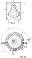
- Figure 1 is a perspective view of a support according to the invention, particularly a bicycle saddle;
- Figure 2 is a sectional view of the support of Figure 1, taken along the vertical longitudinal plane II-II;
- Figure 3 is a schematic sectional view, taken along a vertical plane, of a mold for performing the method according to the invention, during use;
- Figure 4 is an enlarged-scale view of a detail of Figure 3;
- Figure 5 is a sectional view of the mold of Figure 3, taken along the plane V-V;
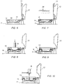
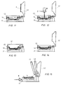
- Figures 6 to 15 schematically illustrate the various steps of the manufacturing method according to the invention for producing the support of Figure 1;
- Figure 16 is a schematic top view of an apparatus for manufacturing according to the invention shown in Figures 6 to 15.
- Figures 1 and 2 illustrate an example of an integral support according to the invention, constituted by a bicycle saddle which is particularly comfortable even for prolonged use and is such as to reduce pressure in the pelvic region and in the urogenital system.
- The saddle 1 includes an
upper covering 2 that covers a multilayer elastic filler, generally designated by thereference numeral 3, and ashell 4 made of semirigid plastic material. In particular, the shell is shaped so as to form a stiffened region and a bracket for anchoring to abicycle frame 5 which is schematically shown in broken lines. - Preferably, the covering can be formed by a multilayer flexible laminar material which includes for example a film of polyurethane material superimposed on a compact base layer of PVC or of PVC-impregnated fabric (Lycra) and on a layer of foamed PVC. The lower surface of the covering is coated with a polyurethane-based primer that contains hydroxyl groups capable of chemically bonding to the filler of the support. The multilayer covering 2 has compactness characteristics combined with a certain softness to the touch and with airtightness to allow its vacuum-forming.
- The
filler 3 includes alower layer 6 constituted by a foamed polymeric resin. An upper layer orinsert 7, made of a gel compound, is superimposed on the lower layer and chemically bonded to it by addition polymerization reactions. The plan dimensions of the insert are smaller than those of the complete support, and when not in use it protrudes upward with respect to the surface of thelower layer 6. The shape of the insert is such as to form a pad of material that yields hydroelastically at the most delicate parts of the user, namely the pelvic bones and the urogenital system. By virtue of the chemical bond between the twolayers layer 7 can be placed directly in contact with thecovering 2, which is in turn chemically bonded both to the gel compound and to the foamed resin. - Advantageously, the gel compound is a polyurethane-based mix in accordance with US patents 4,404,296 and 4,456,642 in the name of the German company Bayer AG, manufactured and marketed by the same company under the trade-name LEVAGEL. In particular, the mix is formed by two main components A and B, where A is constituted by approximately 20% by weight (with respect to the weight of A+B) of a polyurethane matrix having a high relative molecular mass, cross-linked with covalent bonds, and B is approximately 80% by weight (with respect to the weight of A+B) of a liquid dispersant that is closely bonded to the polyurethane matrix by secondary valence forces, with the addition of a catalyst to increase the addition polymerization reactions between the isocyanates and the hydroxyl groups of the two main components and of any additives, such as fibers and dyes. Further details regarding the chemical formula and the process for obtaining this gel compound are included in the above mentioned US patents, the contents of which are included as reference in the present invention. It is interesting to note that the hydroxyl groups contained in component B are present in high stoichiometric excess with respect to the isocyanate groups of compound A, so as to form a urethane polymer dissolved in the polyhydric alcohol excess which gives the compound a gelatinous but firm appearance. After full polymerization, by virtue of the secondary valence forces between the polyhydric alcohols and the urethane matrix the compound maintains a surprising stability even after prolonged use, with repeated impacts and fatigue stresses. The gel also has a low component migration, so that the polyhydric alcohols dissolved in it do not separate from the urethane matrix, and it therefore does not need to be contained in an impermeable capsule or container as in the case of the silicone gels of the prior art. The
gel insert 7 can this be placed directly in contact with the covering 2 and can fully develop its elastic fluid-mechanics properties. - The
lower layer 6 of thefiller 3 can be formed by means of a foamed resin produced by addition polymerization reactions of diols and triols with a relative molecular mass of 4500 to 6000 and methylene diisocyanate-based isocyanates (MDI). The polyurethane foam obtained from the reaction between the isocyanate and the water present in the mix has a density of approximately 150-250 kg/m³. - The
semirigid shell 4 can be produced by molding or cold injection-molding of polymeric materials such as nylon or polypropylene. Preferably, the surface of the shell in contact with the layer of foamed resin is oxidized by combustion, forming on its surface radicals that can chemically attach to the foamed resin of the filler. - The method for manufacturing integral saddles with gel insert of the type shown in Figures 1 and 2 is schematically shown in Figures 6 to 15, and entails the use of a
mold 10 illustrated in Figure 3. - The
mold 10 is formed by alower part 11, by anupper part 12, by anintermediate locking plate 13, and preferably by a second undercutplate 14. Thelower part 11 can be obtained for example from an aluminum alloy block, on the upper surface of which acavity 15 is formed; this cavity is open upward and is shaped complementarily to the resting surface of the support which coincides with the outer surface of thecovering 2.Holes 16 are present on the bottom of thecavity 15 and are connected, by means ofchannels 17, to amanifold channel 18 which can in turn be connected, by means of a pipe, to a vacuum pump V or to an external compressor P. Thelower part 11 also includes acoil 19 through which a liquid at a temperature between 50 and 80oC flows in order to keep the lower part of the mold at a temperature of approximately 40oC throughout the process. Thelower part 11 is anchored to asupport 20 which carries abracket 21. - The
upper part 12 of the mold can also be obtained from an aluminum plate and is preferably internally provided with aheating coil 22. Its lower face 23 is shaped complementarily to thecavity 15 and to the outer face of thesemirigid shell 4 to allow its detachable coupling simply by pressing. The end of thepart 12 is hinged at 24 to thebracket 21 so as to rotate upward and expose thecavity 15. - The locking
plate 13 has a flatlower face 25 that lies peripherally with respect to thecavity 15 with an inner edge that coincides approximately with the upper margin of thecavity 15 and is also pivoted to thebracket 21 at 24. - The
plate 14 has anupper face 26 that is similar to theface 25 of theplate 13 but has, with respect to theface 25, an internal border that protrudes inward by a few millimeters to form an undercut with respect to thecavity 15. In order to improve the seal between theplate 14 and thelower part 11 of the mold, a peripheral slot, in which anannular gasket 27 made of elastomeric material is inserted, can be formed on the mold. - The method for manufacturing the support 1 according to the invention includes a first step, shown in Figure 6, that consists in opening the mold by lifting the
upper part 12 and theplate 13 with respect to thelower part 11, either manually or by means of mechanical actuators, allowing the undercutplate 14 to rest on thepart 11. - The second step entails the laying of a
covering sheet 2 on theplate 14 so as to fully cover thecavity 15, with borders that protrude beyond the edge of theplate 14. Immediately after this, thesheet 2 is heated for a few seconds with an UV (ultraviolet)lamp 28 or with a stream of hot air or with infrared rays, so as to raise it to a temperature between 40 and 150oC, preferably between 80 and 100°C, which is close to the plasticization temperature of the base material. - In the subsequent step, shown in Figure 8, the locking
plate 13 is lowered onto thesheet 2, securing its border against the undercutplate 13. Immediately after this, the sheet is preformed by means of apresser 29 so as to stretch it and move it toward the bottom of thecavity 15. - The step shown in Figure 8 entails the forming of a vacuum on the surface of the
cavity 15 so as to make thecovering 2 adhere perfectly and deform permanently. Conveniently, adepression 30 is formed on the bottom of thecavity 15 of the mold and is suitable to accommodate a part of thefiller 3, forming a corresponding protrusion that extends from the upper surface of the support. - During mechanical and vacuum forming, the border of the
sheet 2 is retained along the entire perimeter of the saddle in different manners between the facing surfaces 25 and 26 of theplates covering 2 in the maximum stress regions, allowing instead a limited slip of the material in the remaining regions of the border, in order to avoid the forming of creases and surface discontinuities. For this purpose, thefaces plates cavity 15 with a play △ which is equal to the thickness of the covering plus 0.1÷0.15 mm. In the regions of maximum stress of the coating, such as the saddle tip and the lateral protrusions, there are additional retention means which are suitable to increase the retaining action by virtue of a larger surface for gripping the material of the covering. As shown in Figures 4 and 5, these retention means can be constituted byrounded protrusions 31 that are formed on one of thesurfaces surface 25, and are arranged opposite to complementarily shapedrecesses 32 formed on theopposite face 26. In the specific case, theprotrusions 31 and therecesses 32 are located toward the tip and the lateral protrusions of the saddle, where the tighter curvature radii of the outer profile produce the highest stresses during forming. - The step of forming the
covering 2 is followed by a step in which the gel compound is poured onto the bottom of the deformed sheet by means of a first foaming head A, as shown in Figure 11. Conveniently, the foaming head A deposits the mixed and fluid gel compound at a temperature of approximately 30oC. The pre-polymerized mixture is poured in preset proportions and quantities at thedepression 30 of the bottom of thecavity 15 so as to fill it completely. This is followed by a step of initial polymerization of the compound at a constant temperature which is maintained by thecoil 19 inserted in thelower part 11 of the mold. According to the invention, the partial polymerization time Tp must be set so as to allow the gel compound to assume a certain consistency and shape of its own, such that it is not deformed by the subsequent pouring of a second filler layer made of a different material. In particular, the fluid gel compound forms a flat meniscus that forms the separation surface of the compound with respect to an adjacent filler layer. - However, polymerization is only partial, so as to prevent the closing of all the chains of the polymeric compounds of the composition, leaving on the surface of the meniscus several open chains and free radical groups that can bind with the expandable resin that will subsequently be poured.
- During the partial polymerization of the gel compound, a
shell 4, meant to be integrated in the support as shown in Figure 11, is coupled to theupper part 12 of the mold. - After the partial polymerization time Tp (of 30 to 80 seconds and preferably 50 to 60 seconds) has elapsed, the expandable polyurethane resin is deposited by means of a second foaming head B which is similar to the first one, as shown in Figure 12.
- The mold is then fully closed and sealed, except for some lateral vents, by placing the
upper part 12 over thelower part 11 and locking theintermediate plates covering 2. In this manner theinsert 7 of gel compound is firmly anchored to the layer of foamedpolyurethane 6 and the two materials are in turn anchored to thecovering 2. The entire assembly is firmly anchored to theshell 4, forming an integral support which is practically finished except for the excess border of thecovering sheet 2. - During the full polymerization step the entire mold may be rocked slightly about a substantially
horizontal axis 33 to tilt thecavity 15 and facilitate discharge of the gases produced inside the mold by the foaming of the resin, by the exothermic addition-polymerization reactions and by the polymerization of the various components. - Figure 15 illustrates the final step of opening of the mold by lifting the
upper part 12, the lockingplate 13 and the undercutplate 14 to allow extraction of the finished saddle. In order to facilitate expulsion of the support 1, the stream of air in the manifold 18 may be reversed by connecting it to a compressor P and producing a slight overpressure sufficient to separate the support from the bottom of thecavity 15. - In order to completely finish the support it is sufficient to remove the excess material of the covering sheet by means of a continuous cutter.
- Figure 16 is a top view of an apparatus that uses a series of molds of the type shown in Figure 3 and uses the above described method in a semi-continuous manner. The apparatus includes a
turntable 34 that is divided into a certain number ofsectors 35 that form the bases for thesupports 20 of themolds 10. The turntable is rotated by means of a gearmotor 36 in steps which have an angular extent equal to that of the sectors in order to place the molds in front of respective stations. The UV-ray lamp 28 and the foaming heads A and B are arranged along the perimeter of theturntable 34; the heads can move radially to place themselves on thedepression 30 of thecavity 15. Thecovering sheet 2 and theshell 4 are inserted manually or by means of mechanical manipulators. The various stations are angularly spaced so as to produce the sequence shown in Figures 6 to 15. - With respect to this sequence it is possible to add a step in which a non-stick releasing product is sprayed along the border of the surface 23 of the
upper part 12 of the mold to prevent the polyurethane foam from sticking to the mold. This step, added after the mold opening step shown in Figure 6, can be produced by means of an appropriateautomatic spray head 37. Actuation of the various parts and rotation of the turntable are controlled by a PLC-type control unit possibly connected to a PC capable of displaying the main parameters of the process. - Although the method and the support according to the invention have been described in a preferred embodiment, it is evident that they are susceptible to numerous modifications and variations, all of which are within the scope of the inventive concept expressed in the accompanying claims. For example, the manufacturing apparatus illustrated in Figure 16 can use a closed-loop conveyor belt instead of a turntable without abandoning the scope of the invention.
- Where technical features mentioned in any claim are followed by reference signs, those reference signs have been included for the sole purpose of increasing the intelligibility of the claims and accordingly, such reference signs do not have any limiting effect on the scope of each element identified by way of example by such reference signs.
Claims (24)
- Method for manufacturing integral elastic supports (1) formed by an upper covering (2), by an intermediate filler (3) and by a lower semirigid shell (4), characterized in that it entails the use of at least one mold (10) that comprises a lower part (11) provided with a cavity (15) that is open upward and reproduces the resting surface of the support, a substantially flat upper part (12) that reproduces the bottom of the support, and at least one intermediate locking plate (13) for retaining the covering, said method comprising the following steps:a) opening the mold so as to expose the cavity of the lower part of the mold;b) depositing on said lower part a substantially airtight covering sheet (2) the border of which exceeds the contour of said cavity (15);c) securing said excess border against said lower part by superimposing said locking plate (13) on it;d) permanent forming of the covering sheet by producing vacuum on the internal wall of said cavity (15);e) pouring of a first layer of a gel compound (3) in the fluid state onto the bottom of the deformed sheet;f) detachable coupling of a shell (4) made of semirigid plastic to the upper part (12) of the mold;g) pouring of a second layer of an expandable resin in the fluid state onto said first gel layer;h) closing of the mold by superimposing and locking the upper part (12) of the mold on said plate and on said lower part (11) of the mold;i) keeping the mold in closed condition to allow the foaming and complete polymerization of the resin and of the gel compound;k) opening of the mold and removal of the finished support;wherein the expandable resin is poured onto the gel compound after a period of time that is sufficient to allow the compound to assume a certain consistency and shape of its own but is shorter than the full polymerization time of the compound, so as to allow it to react at least partially with said expandable resin.
- Method according to claim 1, wherein said gel compound and said foaming resin have such compositions as to form, prior to their complete polymerization, chemical covalent bonds at their separation surface.
- Method according to claim 2, wherein the separation surface between said gel compound and said foaming resin is constituted by the meniscus of gel compound poured onto the bottom of the deformed covering sheet (2).
- Method according to claim 3, wherein said gel compound consists of a mixture of approximately 20% by weight of a polyurethane matrix with high relative molecular mass with approximately 80% by weight of a liquid dispersant that comprises one or more polyhydric alcohols with hydroxyl groups in higher-than-stoichiometric proportions, with the addition of a catalyst and of possible additives and in the absence of plasticizers.
- Method according to claim 4, wherein said expandable resin is a foaming polyurethane compound that can be obtained by means of the mixing and addition polymerization reaction of one or more polyhydric alcohols with one or more polyisocyanates.
- Method according to claim 1, wherein said minimum time elapsing between the end of the pouring of the gel compound and the beginning of the pouring of the expandable resin is comprised between 30 and 80 seconds and is preferably longer than 50 seconds.
- Method according to claim 6, wherein said gel compound is poured into the lower part of the mold at an initial temperature comprised between 30 and 40oC.
- Method according to claim 7, wherein polymerization and reaction of the gel compound and of the expandable resin while the mold is closed occur at a controlled and substantially constant temperature comprised between approximately 40 and 80oC by appropriate heating of the upper and lower parts of the mold by virtue of separate thermal circuits.
- Method according to claim 1, wherein the gel compound is poured onto the preformed covering sheet at one or more depressions formed on the bottom of the lower part of the mold, said depressions being meant to form, in the finished support, corresponding protrusions in the regions of specific maximum pressure for the body of the user.
- Method according to claim 1, wherein there is a second plate (14) interposed between the first frame and the lower part (11) of the mold, with an internal border that is profiled like the contour of the cavity (15) of said lower part, decreased by a few millimeters in order to fold the covering sheet slightly inward, forming a slight undercut.
- Method according to claim 10, wherein the average play between the locking plate (13) and the second undercut plate (14), during the covering sheet forming step d), is equal to the thickness of the sheet increased by approximately 0.1÷0.15 mm to retain the excess edge of said sheet, allowing its partial sliding to avoid the forming of creases.
- Method according to claim 11, wherein said locking plate and said undercut plate have, along their mutually facing regions, retention means in order to locally apply a stronger securing action to the borders of the sheet at regions that are particularly stressed by deformation.
- Method according to claim 12, wherein said retention means consist of one or more rounded protrusions (31) that are formed on the surface (25) of one of the edges and are suitable to cooperate with oppositely arranged and complementarily shaped recesses (32) formed on the other one of said edges (26) to increase the retention surface with respect to the covering sheet.
- Method according to claim 13, wherein the covering sheet, prior to the vacuum forming step d), is subjected to a step 1) of uniform preheating by irradiation or convection at a temperature comprised between 50 and 120oC, possibly followed by a step m) of mechanical preforming by means of an adapted presser.
- Method according to claim 1, wherein a step n) of deposition of a releasing product along the border of the shell and of the upper part of the mold, in order to avoid adhesion of the expandable resin in these regions, is provided prior to the step b) in which the covering sheet is placed on the lower part of the mold.
- Method according to claim 1, wherein the mold, after the closing step h), is tilted slightly with respect to a horizontal plane to facilitate discharge of the gases generated inside it during the foaming and cross-linking of the resin and its reaction with the gel compound.
- Method according to claim 1, wherein the covering sheet has, on its inner face, at least one layer of a polymer that can bond chemically to the gel compound and to the expandable resin.
- Method according to claim 1, wherein a slight overpressure is produced, after opening the mold, on the inner surface of said lower part in order to facilitate extraction of the finished support.
- Semi-continuous method according to the preceding claims, wherein multiple molds (10) are mounted on respective consecutive processing units, said units being jogged synchronously with respect to a first stationary foaming head A for the pouring of a gel compound, followed by a second stationary foaming head B for the pouring of an expandable resin, the advancement rate of said units and the pouring times of said foaming heads being adjusted so as to achieve the partial polymerization of said gel compound inside each individual mold so as to give it a consistency and shape of its own prior to the pouring of said expandable resin but such as to allow the forming of chemical bonds between said gel compound and said expandable resin.
- Semi-continuous method according to claim 19, wherein said consecutive units are mounted on a turntable (34) that rotates in steps about a substantially vertical axis.
- Semi-continuous method according to claim 19, wherein said consecutive units are mounted on a closed-loop continuous conveyor belt that moves in steps in a preset direction.
- Elastic support, such as a cushion, chair, back or saddle with integrated rigid reinforcement, obtainable by means of a process according to the preceding claims, that comprises an upper covering (2) made of flexible laminar material superimposed on a filler (3) that comprises a layer of foamed resin (6) anchored to a shell (4) made of substantially rigid plastic material, wherein said filler (3) is chemically bonded both to said covering (2) and to said shell (4) to form an integral support (1), at least one insert or layer (7) of a gel compound being interposed between said covering (2) and said foamed resin filler (6), said gel compound being chemically bonded by an addition-polymerization reaction both to said foamed resin layer (6) and to said covering (2), said insert (7) being located in regions of maximum pressure for the body of the user.
- Support according to claim 22, wherein said insert (7) made of gel compound is placed directly in contact with said covering (2) with the interposition of a thin layer of polyurethane primer anchored to the base material of the covering and is chemically bonded both to the covering (2) and to said foamed resin layer (6).
- Support according to claim 22, wherein said gel compound is a mixture of a polyurethane matrix with a liquid dispersant that has no plasticizers and has characteristics of high consistency, stability and lack of migration of its components.
Applications Claiming Priority (2)
| Application Number | Priority Date | Filing Date | Title |
|---|---|---|---|
| ITVI930163 IT1270728B (en) | 1993-10-19 | 1993-10-19 | METHOD FOR THE REALIZATION OF INTEGRAL ELASTIC SUPPORTS, AS WELL AS SUPPORTS OBTAINED WITH IT |
| ITVI930163 | 1993-10-19 |
Publications (2)
| Publication Number | Publication Date |
|---|---|
| EP0653279A1 true EP0653279A1 (en) | 1995-05-17 |
| EP0653279B1 EP0653279B1 (en) | 1998-04-22 |
Family
ID=11425343
Family Applications (1)
| Application Number | Title | Priority Date | Filing Date |
|---|---|---|---|
| EP19930119588 Expired - Lifetime EP0653279B1 (en) | 1993-10-19 | 1993-12-06 | Method for manufacturing integral elastic supports, and supports obtained with this method |
Country Status (4)
| Country | Link |
|---|---|
| US (2) | US5441676A (en) |
| EP (1) | EP0653279B1 (en) |
| DE (1) | DE69318159T2 (en) |
| IT (1) | IT1270728B (en) |
Cited By (18)
| Publication number | Priority date | Publication date | Assignee | Title |
|---|---|---|---|---|
| EP0903321A2 (en) * | 1997-09-19 | 1999-03-24 | SELLE ROYAL S.p.A. | Integral elastic support structure with ornamental elements and method for manufacturing such structure |
| EP0952072A3 (en) * | 1998-04-24 | 2000-09-06 | S M P SELLE S.a.s. | Process for the production of padded articles, in particular saddles |
| FR2818187A1 (en) * | 2000-12-20 | 2002-06-21 | Cera | Motor vehicle seat component made by injecting two layers of foam after positioning front and back covering layers in mould |
| EP1078847A3 (en) * | 1999-08-26 | 2002-06-26 | Herbert Huessmanns | Bicycle seat cover |
| WO2003037605A1 (en) * | 2001-10-31 | 2003-05-08 | 3M Innovative Properties Company | Methods of thermoforming non-self-supporting polymeric films and articles made therefrom |
| EP1388402A1 (en) * | 2002-05-22 | 2004-02-11 | Swei Mu Wang | Wear-resistant three-dimensional foamable structure and method for manufacturing it |
| WO2005032922A1 (en) * | 2003-10-03 | 2005-04-14 | Selle Royal Spa | Viscoelastic support structure with improved energy absorption properties |
| WO2006092678A2 (en) * | 2005-01-28 | 2006-09-08 | Selle Royal S.P.A. | Ergonomic support structure made of composite material for human body parts and method of manufacturing it |
| WO2007020571A1 (en) * | 2005-08-12 | 2007-02-22 | Selle Royal S.P.A. | Methods of manufacturing integral elastic supports, and supports obtained with this method |
| US7361402B2 (en) | 2001-10-31 | 2008-04-22 | 3M Innovative Properties Company | Cross-linked primer composition and use thereof in thermoformable films |
| WO2013014655A1 (en) * | 2011-07-28 | 2013-01-31 | Selle Royal S.P.A. | Support for human body parts |
| WO2014002047A1 (en) * | 2012-06-27 | 2014-01-03 | Ergoview Ag | Improved support structure for the human body |
| EP2799203A1 (en) * | 2013-04-30 | 2014-11-05 | Velo Enterprise Co., Ltd. | Methods for producing bicycle saddles |
| EP2798979A1 (en) | 2013-05-03 | 2014-11-05 | Yves Moillo | Method for manufacturing a sealed mattress and sealed mattress thus obtained |
| WO2015008110A1 (en) | 2013-07-17 | 2015-01-22 | Selle Royal S.P.A. | Device and method for the manufacturing of a support for the human body |
| WO2016085788A1 (en) * | 2014-11-26 | 2016-06-02 | Jay Eric C | Bicycle seat |
| EP3090933A1 (en) * | 2015-05-08 | 2016-11-09 | Velo Enterprise Co., Ltd. | Method of manufacturing main body of bicycle saddle |
| IT201800003144A1 (en) * | 2018-02-28 | 2019-08-28 | Selle Royal Spa | MALE COMPONENT AND RESPECTIVE MOLDING UNIT FOR THE PRODUCTION OF A SUPPORT ELEMENT FOR THE HUMAN BODY, SUCH AS A SEAT OF A VEHICLE. |
Families Citing this family (50)
| Publication number | Priority date | Publication date | Assignee | Title |
|---|---|---|---|---|
| JPH0994362A (en) * | 1995-09-28 | 1997-04-08 | Howa Kasei:Kk | Skinned and molded cushion body and molding method therefor |
| US5857749A (en) * | 1996-05-28 | 1999-01-12 | Jay Medical Ltd. | Wheelchair seat assembly with contoured seat pan and cushion and method |
| GB9623817D0 (en) * | 1996-11-16 | 1997-01-08 | Cox Brian A | Improved saddle for pedal-driven machines |
| US5904396A (en) * | 1997-10-22 | 1999-05-18 | Yates; Paul M. | Cushioned bicycle saddle |
| US6131994A (en) * | 1997-10-22 | 2000-10-17 | Yates; Paul M. | Bicycle saddle |
| JP3285141B2 (en) * | 1997-11-19 | 2002-05-27 | 河西工業株式会社 | Automotive interior parts and method of manufacturing the same |
| ITVI980088A1 (en) | 1998-04-30 | 1999-10-30 | Selle Royal Spa | SADDLE STRUCTURE FOR BICYCLE WITH WEAR PROTECTION |
| AU746672B2 (en) * | 1998-07-24 | 2002-05-02 | Thomas H. White | Bicycle seat assembly |
| US6135550A (en) * | 1999-04-01 | 2000-10-24 | Tucho; Tafesse | Bicycle seat |
| US6314598B1 (en) * | 1999-04-08 | 2001-11-13 | Paul M. Yates | Printed elastomeric decorative cushion |
| US6390548B1 (en) * | 1999-05-28 | 2002-05-21 | Clarence Cole | Bicycle seat with inflatable interior |
| US6343839B1 (en) * | 1999-12-17 | 2002-02-05 | Steelcase Development Corporation | Flexible armrest construction |
| IT1317436B1 (en) * | 2000-04-28 | 2003-07-09 | Selle Italia Srl | SELLA STRUCTURE, PARTICULARLY DESIGNED FOR CYCLES |
| US6409865B1 (en) * | 2000-05-01 | 2002-06-25 | Paul M. Yates | Bicycle saddle production method |
| IT1315498B1 (en) * | 2000-08-04 | 2003-02-18 | Selle Royal Spa | SADDLE IN COMPOSITE MATERIAL, IN PARTICULAR FOR BICYCLE AND METHOD FOR ITS REALIZATION |
| US6450572B1 (en) * | 2001-05-04 | 2002-09-17 | Raymond J. Kuipers | Total comfort bicycle saddle |
| FR2848904B1 (en) * | 2002-12-23 | 2006-09-08 | Faurecia Automotive Ind | METHOD FOR PRODUCING A VARIABLE THICKNESS SOUND PIECE |
| DE102004033139B4 (en) * | 2004-07-08 | 2014-04-03 | Bayerische Motoren Werke Aktiengesellschaft | Plastic composite molding and process for its preparation |
| DE202004016000U1 (en) * | 2004-10-15 | 2004-12-23 | Büchel GmbH & Co. Fahrzeugteilefabrik KG | bicycle seat |
| ITVI20040254A1 (en) * | 2004-10-26 | 2005-01-26 | Selle Royal Spa | STRUCTURE OF SADDLE WITH A MEMORY OF SHAPE, PARTICULARLY FOR PEDAL VEHICLES, AS WELL AS THE METHOD OF REALIZING THIS STRUCTURE |
| ITMI20042261A1 (en) * | 2004-11-22 | 2005-02-22 | Selle Italia Srl | STRUCTURE OF SADDLE FOR CYCLES IN GENERAL GIVEN WITH GREATER COMFORT |
| US20070061978A1 (en) * | 2005-03-21 | 2007-03-22 | Technogel Italia Srl | Support apparatus with gel layer |
| US20130000045A1 (en) * | 2005-03-21 | 2013-01-03 | Massimo Losio | Support apparatus with gel layer |
| CN1328035C (en) * | 2005-04-15 | 2007-07-25 | 江阴嘉思特车业有限公司 | Method of making bicycle saddle using sewing or split joined saddle surface vacuum suction moulding |
| ITVI20060032A1 (en) * | 2006-01-31 | 2007-08-01 | Selle Royal Spa | METHOD FOR THE REALIZATION OF INTEGRAL ELASTIC SUPPORTS |
| US20070246157A1 (en) * | 2006-04-25 | 2007-10-25 | Technogel Gmbh & Co. | Process for preparing an apparatus comprising a gel layer |
| US20080018147A1 (en) * | 2006-05-30 | 2008-01-24 | David Ybarrola | Contoured bicycle saddle and method of manufacturing |
| US7754127B2 (en) * | 2006-09-30 | 2010-07-13 | Let's Gel, Inc. | Method for fabricating an anti-fatigue mat |
| FR2942110B1 (en) * | 2009-02-13 | 2011-03-04 | Millet Innovation | METHOD FOR MANUFACTURING A DEVICE FOR PROTECTING A ZONE OF THE HUMAN BODY |
| US20110198903A1 (en) * | 2010-02-12 | 2011-08-18 | Ivan Sebastian | Elastomeric bicycle saddle cover |
| IT1400939B1 (en) | 2010-05-13 | 2013-07-02 | Selle Royal Spa | IMPROVED SEAT SUPPORT |
| ITVR20110052A1 (en) * | 2011-03-11 | 2012-09-12 | Selle Royal Spa | SUPPORTING ELEMENT FOR THE HUMAN BODY |
| US9073593B1 (en) | 2011-08-18 | 2015-07-07 | Steven D. Kuhl | Adjustable pneumatic bicycle saddle system |
| US9290222B1 (en) | 2011-08-18 | 2016-03-22 | Steven D. Kuhl | Adjustable pneumatic bicycle saddle system with improved pump |
| WO2015186009A1 (en) | 2014-06-05 | 2015-12-10 | Green Foam S.R.L. | A pillow in polyurethane gel and foam with a layer in fabric or non-woven fabric (tnt) interposed between foam and gel |
| US10124515B2 (en) * | 2014-09-16 | 2018-11-13 | Tempur-Pedic Management, Llc | Gel molded pillow and method of producing the same |
| TWI565617B (en) | 2015-08-03 | 2017-01-11 | Bicycle seat cushion body with auxiliary function sheet and manufacturing method thereof | |
| CN105539639B (en) * | 2016-03-02 | 2018-04-03 | 温岭东方红车料有限公司 | A kind of bicycle saddle, its process equipment and its processing technology |
| TWI597148B (en) | 2017-01-13 | 2017-09-01 | Bicycle seat system of the law | |
| US10471860B2 (en) * | 2017-04-12 | 2019-11-12 | Rob VanPay | Apparatus and system for seat replacements for vehicles |
| IT201700077584A1 (en) * | 2017-07-10 | 2019-01-10 | Selle Royal Spa | MOLD FOR AN ELEMENT OF SUPPORT FOR THE HUMAN BODY, AS A SADDLE |
| TWI613068B (en) * | 2017-08-23 | 2018-02-01 | Anti-slip yoga towel manufacturing method and anti-slip yoga towel made by using the manufacturing method | |
| US10882576B2 (en) * | 2018-03-21 | 2021-01-05 | Ddk Group Co., Ltd., Taiwan Branch | Bike saddle incorporating with bio-gel structure |
| TWM564548U (en) * | 2018-03-21 | 2018-08-01 | 宋盈嬌 | Bicycle seat cushion combined with bio gel structure |
| CN108908839B (en) * | 2018-06-20 | 2020-11-27 | 温岭东方红车料有限公司 | Integral elastic support and method for manufacturing same |
| US11760431B2 (en) | 2018-10-02 | 2023-09-19 | Xsensor Technology Corporation | Bicycle seat for improved comfort, performance, and safety |
| US11052958B2 (en) | 2018-10-02 | 2021-07-06 | Xsensor Technology Corporation | Bicycle seats |
| EP4217259A1 (en) * | 2020-09-26 | 2023-08-02 | Xsensor Technology Corporation | Bicycle seat for improved comfort, performance, and safety |
| WO2024023717A1 (en) * | 2022-07-26 | 2024-02-01 | Selle Royal S.P.A. | Plant and method for manufacturing a support element for the human body, such as a vehicle saddle |
| US11938850B2 (en) * | 2022-08-03 | 2024-03-26 | Faurecia Automotive Seating, Llc | Vehicle seat cushion with integrated ventilation |
Citations (4)
| Publication number | Priority date | Publication date | Assignee | Title |
|---|---|---|---|---|
| US3161436A (en) * | 1962-03-27 | 1964-12-15 | Davidson Rubber Company Inc | Pre-stressed molded foam cushioning element |
| US3712771A (en) * | 1971-06-24 | 1973-01-23 | Koehring Co | Traveling mold mechanism for forming plastic articles |
| FR2339482A1 (en) * | 1976-01-30 | 1977-08-26 | Veldeman Valere | Moulding covered foam article holding cover against lip of mould - and deforming by suction before injecting foam |
| US4999068A (en) * | 1986-02-24 | 1991-03-12 | Chiarella Michele A | Method for making an anatomical multilayer bicycle-type seat |
Family Cites Families (23)
| Publication number | Priority date | Publication date | Assignee | Title |
|---|---|---|---|---|
| US718850A (en) * | 1901-06-10 | 1903-01-20 | Johannes Alexandre Kruseman | Cycle-saddle. |
| US2976577A (en) * | 1958-04-14 | 1961-03-28 | Gen Motors Corp | Process of making foam cored laminates |
| US3020260A (en) * | 1960-08-18 | 1962-02-06 | Dow Corning | Organosiloxane potting compound |
| US3187069A (en) * | 1962-09-28 | 1965-06-01 | Kay Mfg Corp | Making foamed articles |
| US3487134A (en) * | 1964-03-26 | 1969-12-30 | Goodyear Tire & Rubber | Method for manufacturing a textured surfaced composite foamed article and the mold therefor |
| US3548420A (en) * | 1967-03-06 | 1970-12-22 | Stryker Corp | Cushion structure |
| US3773875A (en) * | 1968-04-01 | 1973-11-20 | Goodyear Tire & Rubber | Method of making foamed articles having a reinforcing member |
| US3663973A (en) * | 1970-12-16 | 1972-05-23 | Stryker Corp | Cushion structure |
| US3807793A (en) * | 1972-02-09 | 1974-04-30 | D Jacobs | Bicycle seat |
| DE2249652A1 (en) * | 1972-10-11 | 1974-04-25 | Bayer Ag | METHOD AND DEVICE FOR MANUFACTURING A FOAM PAD |
| US4012072A (en) * | 1976-01-19 | 1977-03-15 | Hansen Leif A | Flexing multi-firmness seat cover |
| US4130614A (en) * | 1976-02-02 | 1978-12-19 | Exxon Research & Engineering Co. | Method for making structural foams with facing sheets |
| DE3034973C2 (en) * | 1980-09-17 | 1983-11-24 | Metzeler Schaum Gmbh, 8940 Memmingen | Device for pulling upholstery material into a foam backing mold |
| DE3103564A1 (en) * | 1981-02-03 | 1982-08-26 | Bayer Ag, 5090 Leverkusen | GEL UPHOLSTERY, METHOD FOR THE PRODUCTION AND USE THEREOF |
| JPS5829633A (en) * | 1981-08-13 | 1983-02-21 | Meiwa Sangyo Kk | Manufacture of composite molded item |
| WO1983003195A1 (en) * | 1982-03-16 | 1983-09-29 | Jay, Eric, C. | Improved seat cushion |
| US4808469A (en) * | 1985-05-09 | 1989-02-28 | Maurice Hiles | Energy absorbing polyurethane composite article |
| US4815361A (en) * | 1986-02-24 | 1989-03-28 | Chiarella Michele A | Anatomical multilayer bicycle seat and method for making same |
| JPS62257825A (en) * | 1986-05-02 | 1987-11-10 | Toyota Auto Body Co Ltd | Molding method of sheet material |
| US4766025A (en) * | 1986-09-25 | 1988-08-23 | Sheller Globe Corp. | Composite molded article and method of making same |
| DE3739257C1 (en) * | 1987-11-18 | 1988-09-15 | Fritsche Moellmann Gmbh Co Kg | Device for producing upholstered upholstered covers |
| AU616075B2 (en) * | 1988-11-24 | 1991-10-17 | Bridgestone Australia Ltd. | Vehicle inner panel |
| US5207957A (en) * | 1991-08-08 | 1993-05-04 | Ford Motor Company | Method for producing a foamed panel |
-
1993
- 1993-10-19 IT ITVI930163 patent/IT1270728B/en active IP Right Grant
- 1993-12-06 DE DE1993618159 patent/DE69318159T2/en not_active Expired - Lifetime
- 1993-12-06 EP EP19930119588 patent/EP0653279B1/en not_active Expired - Lifetime
- 1993-12-17 US US08/168,211 patent/US5441676A/en not_active Expired - Lifetime
-
1995
- 1995-08-03 US US08/510,842 patent/US5670232A/en not_active Expired - Lifetime
Patent Citations (4)
| Publication number | Priority date | Publication date | Assignee | Title |
|---|---|---|---|---|
| US3161436A (en) * | 1962-03-27 | 1964-12-15 | Davidson Rubber Company Inc | Pre-stressed molded foam cushioning element |
| US3712771A (en) * | 1971-06-24 | 1973-01-23 | Koehring Co | Traveling mold mechanism for forming plastic articles |
| FR2339482A1 (en) * | 1976-01-30 | 1977-08-26 | Veldeman Valere | Moulding covered foam article holding cover against lip of mould - and deforming by suction before injecting foam |
| US4999068A (en) * | 1986-02-24 | 1991-03-12 | Chiarella Michele A | Method for making an anatomical multilayer bicycle-type seat |
Cited By (26)
| Publication number | Priority date | Publication date | Assignee | Title |
|---|---|---|---|---|
| EP0903321A3 (en) * | 1997-09-19 | 2000-04-26 | SELLE ROYAL S.p.A. | Integral elastic support structure with ornamental elements and method for manufacturing such structure |
| EP0903321A2 (en) * | 1997-09-19 | 1999-03-24 | SELLE ROYAL S.p.A. | Integral elastic support structure with ornamental elements and method for manufacturing such structure |
| EP0952072A3 (en) * | 1998-04-24 | 2000-09-06 | S M P SELLE S.a.s. | Process for the production of padded articles, in particular saddles |
| EP1078847A3 (en) * | 1999-08-26 | 2002-06-26 | Herbert Huessmanns | Bicycle seat cover |
| FR2818187A1 (en) * | 2000-12-20 | 2002-06-21 | Cera | Motor vehicle seat component made by injecting two layers of foam after positioning front and back covering layers in mould |
| US7361402B2 (en) | 2001-10-31 | 2008-04-22 | 3M Innovative Properties Company | Cross-linked primer composition and use thereof in thermoformable films |
| WO2003037605A1 (en) * | 2001-10-31 | 2003-05-08 | 3M Innovative Properties Company | Methods of thermoforming non-self-supporting polymeric films and articles made therefrom |
| US7507363B2 (en) | 2001-10-31 | 2009-03-24 | 3M Innovative Properties Company | Methods of thermoforming non-self-supporting polymeric films and articles made therefrom |
| EP1388402A1 (en) * | 2002-05-22 | 2004-02-11 | Swei Mu Wang | Wear-resistant three-dimensional foamable structure and method for manufacturing it |
| WO2005032922A1 (en) * | 2003-10-03 | 2005-04-14 | Selle Royal Spa | Viscoelastic support structure with improved energy absorption properties |
| WO2006092678A3 (en) * | 2005-01-28 | 2006-11-23 | Selle Royal Spa | Ergonomic support structure made of composite material for human body parts and method of manufacturing it |
| WO2006092678A2 (en) * | 2005-01-28 | 2006-09-08 | Selle Royal S.P.A. | Ergonomic support structure made of composite material for human body parts and method of manufacturing it |
| WO2007020571A1 (en) * | 2005-08-12 | 2007-02-22 | Selle Royal S.P.A. | Methods of manufacturing integral elastic supports, and supports obtained with this method |
| WO2013014655A1 (en) * | 2011-07-28 | 2013-01-31 | Selle Royal S.P.A. | Support for human body parts |
| CN103826966A (en) * | 2011-07-28 | 2014-05-28 | 塞莱皇家股份公司 | Support for human body parts |
| WO2014002047A1 (en) * | 2012-06-27 | 2014-01-03 | Ergoview Ag | Improved support structure for the human body |
| EP2799203A1 (en) * | 2013-04-30 | 2014-11-05 | Velo Enterprise Co., Ltd. | Methods for producing bicycle saddles |
| EP2798979A1 (en) | 2013-05-03 | 2014-11-05 | Yves Moillo | Method for manufacturing a sealed mattress and sealed mattress thus obtained |
| FR3005283A1 (en) * | 2013-05-03 | 2014-11-07 | Yves Moillo | METHOD OF MANUFACTURING A SEALED MATTRESS AND SEALED MATTRESS THUS OBTAINED |
| WO2015008110A1 (en) | 2013-07-17 | 2015-01-22 | Selle Royal S.P.A. | Device and method for the manufacturing of a support for the human body |
| WO2016085788A1 (en) * | 2014-11-26 | 2016-06-02 | Jay Eric C | Bicycle seat |
| US10435097B2 (en) | 2014-11-26 | 2019-10-08 | Jarik Medical, LLC | Bicycle seat for protecting ischial tuberosities |
| EP3090933A1 (en) * | 2015-05-08 | 2016-11-09 | Velo Enterprise Co., Ltd. | Method of manufacturing main body of bicycle saddle |
| IT201800003144A1 (en) * | 2018-02-28 | 2019-08-28 | Selle Royal Spa | MALE COMPONENT AND RESPECTIVE MOLDING UNIT FOR THE PRODUCTION OF A SUPPORT ELEMENT FOR THE HUMAN BODY, SUCH AS A SEAT OF A VEHICLE. |
| CN111954591A (en) * | 2018-02-28 | 2020-11-17 | 赛尔皇家股份公司 | Male element for producing a vehicle saddle and corresponding die unit |
| CN111954591B (en) * | 2018-02-28 | 2023-02-24 | 赛尔皇家股份公司 | Male element for producing a vehicle saddle and corresponding die unit |
Also Published As
| Publication number | Publication date |
|---|---|
| DE69318159T2 (en) | 1998-08-20 |
| IT1270728B (en) | 1997-05-07 |
| US5441676A (en) | 1995-08-15 |
| EP0653279B1 (en) | 1998-04-22 |
| ITVI930163A1 (en) | 1994-01-19 |
| ITVI930163A0 (en) | 1993-10-19 |
| DE69318159D1 (en) | 1998-05-28 |
| US5670232A (en) | 1997-09-23 |
Similar Documents
| Publication | Publication Date | Title |
|---|---|---|
| EP0653279B1 (en) | Method for manufacturing integral elastic supports, and supports obtained with this method | |
| US6120630A (en) | Method of making a seat cushion | |
| US4116736A (en) | Method of making a foam plastic cushion having a peripheral frame and an exterior cover | |
| JP3220905B2 (en) | Method for producing stuffed components | |
| JP4327921B2 (en) | Integrated elastic support structure and manufacturing method thereof | |
| AU600349B2 (en) | Plastic, trough-shaped sanitary article, in particular, bathtub | |
| US20160136911A1 (en) | Molding system, method and articles formed thereby | |
| US4844761A (en) | Method for the manufacture of a padded element, particularly a seat cushion | |
| CA2334125A1 (en) | Custom-molded cushion and method of making the same | |
| US3623931A (en) | Method of making plastic cushion product | |
| WO1995013911A1 (en) | Process for manufacturing a padded element | |
| US4975229A (en) | Process for producing laminated resin foam | |
| GB2219964A (en) | Method of molding skin-covered foamed article | |
| US3517396A (en) | Cushion toilet seat structure | |
| US5324462A (en) | Process for the manufacture of moulded material-covered product | |
| EP1060859B1 (en) | Method for moulding seat tops or the like having a gel coating layer | |
| JPH04811B2 (en) | ||
| US5227176A (en) | Mold for a shaped laminate | |
| CN111655568B (en) | Method for manufacturing a seat with an additional gel pad, seat thus obtained and apparatus for implementing the method | |
| US20040146704A1 (en) | Vehicular headliner and method for production thereof | |
| JPH11151767A (en) | Large-sized container and its production | |
| EP1407867A2 (en) | Seat and procedure for making seats with additional padding preapplied to the covering | |
| EP0347503A1 (en) | Process for manufacture of material-covered product | |
| CN218683221U (en) | Inflatable cushion with air permeability improving function | |
| TWI617418B (en) | Improved molding system, method and articles formed thereby |
Legal Events
| Date | Code | Title | Description |
|---|---|---|---|
| PUAI | Public reference made under article 153(3) epc to a published international application that has entered the european phase |
Free format text: ORIGINAL CODE: 0009012 |
|
| AK | Designated contracting states |
Kind code of ref document: A1 Designated state(s): DE IT NL |
|
| 17P | Request for examination filed |
Effective date: 19950406 |
|
| 17Q | First examination report despatched |
Effective date: 19960715 |
|
| GRAG | Despatch of communication of intention to grant |
Free format text: ORIGINAL CODE: EPIDOS AGRA |
|
| GRAG | Despatch of communication of intention to grant |
Free format text: ORIGINAL CODE: EPIDOS AGRA |
|
| GRAH | Despatch of communication of intention to grant a patent |
Free format text: ORIGINAL CODE: EPIDOS IGRA |
|
| GRAH | Despatch of communication of intention to grant a patent |
Free format text: ORIGINAL CODE: EPIDOS IGRA |
|
| GRAA | (expected) grant |
Free format text: ORIGINAL CODE: 0009210 |
|
| AK | Designated contracting states |
Kind code of ref document: B1 Designated state(s): DE IT NL |
|
| ITF | It: translation for a ep patent filed |
Owner name: ING. ZINI MARANESI & C. S.R.L. |
|
| REF | Corresponds to: |
Ref document number: 69318159 Country of ref document: DE Date of ref document: 19980528 |
|
| PLBE | No opposition filed within time limit |
Free format text: ORIGINAL CODE: 0009261 |
|
| STAA | Information on the status of an ep patent application or granted ep patent |
Free format text: STATUS: NO OPPOSITION FILED WITHIN TIME LIMIT |
|
| 26N | No opposition filed | ||
| PGFP | Annual fee paid to national office [announced via postgrant information from national office to epo] |
Ref country code: IT Payment date: 20120713 Year of fee payment: 20 |
|
| PGFP | Annual fee paid to national office [announced via postgrant information from national office to epo] |
Ref country code: DE Payment date: 20121231 Year of fee payment: 20 |
|
| PGFP | Annual fee paid to national office [announced via postgrant information from national office to epo] |
Ref country code: NL Payment date: 20121225 Year of fee payment: 20 |
|
| REG | Reference to a national code |
Ref country code: DE Ref legal event code: R071 Ref document number: 69318159 Country of ref document: DE |
|
| REG | Reference to a national code |
Ref country code: NL Ref legal event code: V4 Effective date: 20131206 |
|
| PG25 | Lapsed in a contracting state [announced via postgrant information from national office to epo] |
Ref country code: DE Free format text: LAPSE BECAUSE OF EXPIRATION OF PROTECTION Effective date: 20131207 |