EP0653115B1 - Gleichstromschaltungsanordnung mit polaritätsumkehrung für entfernt gelegene einrichtungen - Google Patents
Gleichstromschaltungsanordnung mit polaritätsumkehrung für entfernt gelegene einrichtungen Download PDFInfo
- Publication number
- EP0653115B1 EP0653115B1 EP93918255A EP93918255A EP0653115B1 EP 0653115 B1 EP0653115 B1 EP 0653115B1 EP 93918255 A EP93918255 A EP 93918255A EP 93918255 A EP93918255 A EP 93918255A EP 0653115 B1 EP0653115 B1 EP 0653115B1
- Authority
- EP
- European Patent Office
- Prior art keywords
- power
- signal control
- cable
- control apparatus
- subscriber
- Prior art date
- Legal status (The legal status is an assumption and is not a legal conclusion. Google has not performed a legal analysis and makes no representation as to the accuracy of the status listed.)
- Expired - Lifetime
Links
- 239000003990 capacitor Substances 0.000 claims description 17
- 230000007797 corrosion Effects 0.000 abstract description 11
- 238000005260 corrosion Methods 0.000 abstract description 11
- 230000035939 shock Effects 0.000 abstract description 10
- 238000005868 electrolysis reaction Methods 0.000 abstract description 6
- 238000006243 chemical reaction Methods 0.000 description 9
- 230000005540 biological transmission Effects 0.000 description 8
- 239000004020 conductor Substances 0.000 description 8
- 238000004891 communication Methods 0.000 description 4
- 230000001105 regulatory effect Effects 0.000 description 4
- 238000010586 diagram Methods 0.000 description 3
- 230000000694 effects Effects 0.000 description 3
- 239000000835 fiber Substances 0.000 description 3
- RYGMFSIKBFXOCR-UHFFFAOYSA-N Copper Chemical compound [Cu] RYGMFSIKBFXOCR-UHFFFAOYSA-N 0.000 description 2
- 229910052782 aluminium Inorganic materials 0.000 description 2
- 229910052802 copper Inorganic materials 0.000 description 2
- 239000010949 copper Substances 0.000 description 2
- 238000009434 installation Methods 0.000 description 2
- 239000000463 material Substances 0.000 description 2
- 230000013011 mating Effects 0.000 description 2
- 229910052751 metal Inorganic materials 0.000 description 2
- 239000002184 metal Substances 0.000 description 2
- 238000012552 review Methods 0.000 description 2
- 238000001228 spectrum Methods 0.000 description 2
- 238000012360 testing method Methods 0.000 description 2
- 208000003663 ventricular fibrillation Diseases 0.000 description 2
- 206010003497 Asphyxia Diseases 0.000 description 1
- 208000007101 Muscle Cramp Diseases 0.000 description 1
- 206010034701 Peroneal nerve palsy Diseases 0.000 description 1
- 208000005392 Spasm Diseases 0.000 description 1
- 229910000831 Steel Inorganic materials 0.000 description 1
- 230000009471 action Effects 0.000 description 1
- XAGFODPZIPBFFR-UHFFFAOYSA-N aluminium Chemical compound [Al] XAGFODPZIPBFFR-UHFFFAOYSA-N 0.000 description 1
- 238000013459 approach Methods 0.000 description 1
- 238000013475 authorization Methods 0.000 description 1
- 238000010009 beating Methods 0.000 description 1
- 206010061592 cardiac fibrillation Diseases 0.000 description 1
- 230000008859 change Effects 0.000 description 1
- 230000001276 controlling effect Effects 0.000 description 1
- 239000003792 electrolyte Substances 0.000 description 1
- 238000005516 engineering process Methods 0.000 description 1
- 239000006260 foam Substances 0.000 description 1
- 239000011888 foil Substances 0.000 description 1
- 230000006870 function Effects 0.000 description 1
- 231100001261 hazardous Toxicity 0.000 description 1
- 239000012535 impurity Substances 0.000 description 1
- 238000003780 insertion Methods 0.000 description 1
- 230000037431 insertion Effects 0.000 description 1
- 150000002739 metals Chemical class 0.000 description 1
- 238000000034 method Methods 0.000 description 1
- 238000012986 modification Methods 0.000 description 1
- 230000004048 modification Effects 0.000 description 1
- NJPPVKZQTLUDBO-UHFFFAOYSA-N novaluron Chemical compound C1=C(Cl)C(OC(F)(F)C(OC(F)(F)F)F)=CC=C1NC(=O)NC(=O)C1=C(F)C=CC=C1F NJPPVKZQTLUDBO-UHFFFAOYSA-N 0.000 description 1
- 230000001151 other effect Effects 0.000 description 1
- 238000003825 pressing Methods 0.000 description 1
- 230000008569 process Effects 0.000 description 1
- 238000012545 processing Methods 0.000 description 1
- 238000010079 rubber tapping Methods 0.000 description 1
- 230000007704 transition Effects 0.000 description 1
- 238000000411 transmission spectrum Methods 0.000 description 1
- 230000001960 triggered effect Effects 0.000 description 1
- XLYOFNOQVPJJNP-UHFFFAOYSA-N water Substances O XLYOFNOQVPJJNP-UHFFFAOYSA-N 0.000 description 1
Images

Classifications
-
- H—ELECTRICITY
- H04—ELECTRIC COMMUNICATION TECHNIQUE
- H04N—PICTORIAL COMMUNICATION, e.g. TELEVISION
- H04N7/00—Television systems
- H04N7/10—Adaptations for transmission by electrical cable
-
- H—ELECTRICITY
- H02—GENERATION; CONVERSION OR DISTRIBUTION OF ELECTRIC POWER
- H02M—APPARATUS FOR CONVERSION BETWEEN AC AND AC, BETWEEN AC AND DC, OR BETWEEN DC AND DC, AND FOR USE WITH MAINS OR SIMILAR POWER SUPPLY SYSTEMS; CONVERSION OF DC OR AC INPUT POWER INTO SURGE OUTPUT POWER; CONTROL OR REGULATION THEREOF
- H02M7/00—Conversion of AC power input into DC power output; Conversion of DC power input into AC power output
- H02M7/42—Conversion of DC power input into AC power output without possibility of reversal
- H02M7/44—Conversion of DC power input into AC power output without possibility of reversal by static converters
- H02M7/48—Conversion of DC power input into AC power output without possibility of reversal by static converters using discharge tubes with control electrode or semiconductor devices with control electrode
- H02M7/53—Conversion of DC power input into AC power output without possibility of reversal by static converters using discharge tubes with control electrode or semiconductor devices with control electrode using devices of a triode or transistor type requiring continuous application of a control signal
- H02M7/537—Conversion of DC power input into AC power output without possibility of reversal by static converters using discharge tubes with control electrode or semiconductor devices with control electrode using devices of a triode or transistor type requiring continuous application of a control signal using semiconductor devices only, e.g. single switched pulse inverters
- H02M7/538—Conversion of DC power input into AC power output without possibility of reversal by static converters using discharge tubes with control electrode or semiconductor devices with control electrode using devices of a triode or transistor type requiring continuous application of a control signal using semiconductor devices only, e.g. single switched pulse inverters in a push-pull configuration
-
- H—ELECTRICITY
- H04—ELECTRIC COMMUNICATION TECHNIQUE
- H04B—TRANSMISSION
- H04B3/00—Line transmission systems
- H04B3/02—Details
- H04B3/44—Arrangements for feeding power to a repeater along the transmission line
-
- H—ELECTRICITY
- H04—ELECTRIC COMMUNICATION TECHNIQUE
- H04H—BROADCAST COMMUNICATION
- H04H20/00—Arrangements for broadcast or for distribution combined with broadcast
- H04H20/65—Arrangements characterised by transmission systems for broadcast
- H04H20/76—Wired systems
- H04H20/77—Wired systems using carrier waves
- H04H20/78—CATV [Community Antenna Television] systems
Definitions
- the present invention relates generally to power supply circuits, and more particularly relates to a polarity reversing DC power supply circuit for remotely located equipment, particularly usefuly for powering cable television signal control apparatus located remotely from and connected to a subscriber facility and primary power supply by a conductor such as a drop cable.
- a third and primary concern is safety if power is being supplied from the subscriber's facility so as to ensure that no shock hazard will be created.
- the latter concern is especially important in cable television distribution systems for home viewing, since cable subscribers often connect and disconnect their own cable equipment such as VCR's, cable converters, and the like.
- an off-premises cable television interdiction apparatus comprises a microprocessor actuation and control means for actuating and controlling a plurality of frequency agile voltage controlled oscillators.
- the voltage controlled oscillators selectively jam only unauthorized premium programming transmitted "in the clear" from a headend system to a particular subscriber.
- the interdiction system prevents the reception of jammed premium programming by the unauthorized subscriber.
- a frequency hopping circuit operates to receive and store voltage control words for operating the oscillators consistent with a headend selected jamming factor for a particular channel to be jammed and addressably transmitted and stored premium programming authorization data.
- Off-premises interdiction and other signal control devices contain electrical devices for receipt, processing, and storage of control information signals from the headend as well as for re-transmission or jamming of the programming signal, and require electrical power for operation.
- the devices present to be powered typically include at least one microprocessor, associated memory, voltage controlled oscillators, broadband amplifiers, video amplifiers, and other electrical components. These circuits can draw as much as about 25 watts of power for each subscriber. Although 25 watts per subscriber is a relatively nominal power drain if taken alone, or if provided by the individual subscribers, the aggregate power requirements for a large cable system would nevertheless constitute a significant cost factor to the operator if the entire system were required to provide power for the interdiction systems for all subscribers.
- Some off-premises signal control systems have power consumptions per subscriber of about 4 watts for interdiction systems and up to about 35 watts for frequency (channel) conversion systems. For a system designed for about eighty subscribers per mile, the signal control power consumption would be 240 watts per mile for an interdiction system, and 1,200 watts per mile for a frequency conversion system. It will thus be understood that the power requirements for the cable operator can be substantial in a large system. Additionally, it is known that approximately 15-20 percent of power supplied is actually lost as heat in trunk and feeder cables. For example, in carrying 10 amps through one mile of 3/4 inch copper clad aluminum center conductor GID cable, 380 watts are dissipated. For smaller cables, such as 1/2 inch cable, up to 866 watts is lost.
- VAC 120 volts alternating current
- One prior art approach is the provision of off-premises power supply circuitry that interrupts the voltage leaving an in-premises power supply if the drop current is interrupted.
- the system automatically restarts if some other subscriber or subscribers are still supplying power to the off-premises device. If that subscriber was the only one supplying power, he may attempt to restart by pressing an "on" button. Power will come on for a predetermined time period of several hundred milliseconds, and if no data communications are established from the off-premises device within that time, the system assumes drop integrity has still not been restored and voltage is again interrupted. This timing is considered sufficiently shorter than the time required for a shock hazard to be generated at the voltages involved.
- AC is generally favored by the CATV operator's community due to fewer problems with corrosion as a result of electrolysis.
- use of AC presents difficulties of successfully powering the equipment while meeting applicable regulatory and safety requirements.
- Use of DC would overcome the regulatory and safety difficulties, but presents a corrosion difficulty.
- electromechanical connections In a typical CATV subscriber connection, electrical power must pass through at least four electromechanical connections -- one at the power source, two at a ground block just outside the subscriber's premises, and one at the off-premises equipment.
- Each of these connections is typically made with the F-connector commonly used in the CATV industry, which is known to be susceptible to corrosion in the presence of direct current. The corrosion effect is explained by Faraday's principles of electrolysis, that the quantity of an element undergoing chemical reaction at an electrode is proportional to the quantity of electric charge passing, proportional to the atomic mass of the element, and inversely proportional to its valence. It is known to those skilled in the art that electrodes are formed at each electromechanical connection in which air can be in proximity to the metal.
- US-3987240 describes a direct current power supply system for providing power from a head end of a cable system to a plurality of coaxial cable amplifiers in a distribution cable of the cable system.
- the system includes means for connecting to a primary AC supply, a step-down transformer, a fullwave rectifier providing positive and negative DC voltages, a switching device and connections to apply the DC onto the cable.
- the switching device is operated about once a month, either manually or by a timer and oscillator, in order to reverse the polarity of the DC supply.
- the document does not teach a power inserting system for supplying power of no more than ⁇ 30 VDC, via a drop cable, from a subscriber facility to a signal control apparatus located remotely from the subscriber facility.
- EP-0158089 describes a reversing direct current power supply system for providing power via a coaxial cable to remote systems.
- the document does not teach the use of low voltage ( ⁇ 30 V DC) supply to meet the particular requirements of subscriber-end power supply via a drop cable, nor does the document teach use of an AC power source.
- the present invention is polarity reversing DC power supply system for powering a signal control apparatus located remotely from a primary AC power source and connected to the signal control apparatus through a conductor having a finite resistance, such as a cable TV drop line.
- Means are provided for connecting to a primary AC source of power, such as 117 VAC.
- Means are provided for stepping down the voltage of the primary AC source of power to a predetermined DC voltage at positive and negative polarities.
- Means are provided for periodically reversing the polarity of the predetermined DC voltage at a frequency lower than the frequency of the primary source of power.
- means are provided for inserting the polarity reversed DC power into the conductor.
- the polarity reversing means comprises a step-down transformer for connecting to 117 VAC power source and for providing AC power at a reduced voltage.
- a full wave rectifier converts the reduced voltage AC power into a positive DC voltage and a negative DC voltage.
- a first switching transistor connects the positive DC voltage to a power buss, and an alternately actuated second switching transistor connects the negative DC voltage to the power buss.
- a constant duty cycle oscillator alternately switching on the first transistor and the second transistor at a predetermined frequency less than 10 Hz, to provide a low frequency polarity reversing DC power.
- the frequency of polarity reversal of the reversing means is less than 10 Hertz, to avoid classification of the reversing polarity DC as "AC" and to avoid shock hazards associated with AC power.
- An RF choke couples the polarity reversing DC power to the drop cable.
- the system provides a source of power for a signal control apparatus in a cable television signal distribution system, wherein the conductor comprises a drop cable, wherein the primary AC source of power is located in a subscriber's facility, and wherein the signal control apparatus is an interdiction system.
- the primary power source connecting means and the stepping down means comprises a AC power pack for connection to 117 VAC and mounted in a first module, and the polarity reversing means and the inserting means are mounted in a second module separate from the first module.
- the present invention finds particular utility in a cable television system comprising a distribution cable, a subscriber facility, a signal control apparatus located remotely from the subscriber facility and connected to the distribution cable, and a drop cable extending between the signal control apparatus and the subscriber facility.
- a system constructed in accordance with the present invention will include a polarity reversing DC power utilization circuit located proximate to the signal control apparatus, for converting the polarity reversing DC to a format suitable for powering the signal control apparatus.
- the preferred power utilization circuit includes a means for connecting to the drop cable, a means for connecting signals from the signal control apparatus to the drop cable, a means for converting the low frequency polarity reversing DC power to single polarity DC power, and a means for connecting the single polarity DC power to power consuming devices in the signal control apparatus. It is expected that the means for connecting the single polarity DC power to power consuming devices will typically comprise a switching power supply.
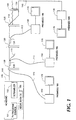
- FIG. 1 is an overall system block diagram showing off-premise signal control apparatus used in a cable television system including interdiction and frequency conversion equipment.
- FIG. 2 illustrates a typical subscriber powering arrangement with an off-premise interdiction device being powered via a drop cable and coax cable to power inserter circuit constructed in accordance with the preferred embodiment of the present invention.
- FIG. 3 is a voltage timing diagram illustrating the difference between alternating current (AC) and polarity reversed direct current (DC) provided in the preferred embodiment of the present invention.
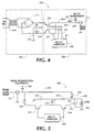
- FIG. 4 illustrates a power inserter circuit constructed in accordance with the preferred embodiment of the present invention.
- FIG. 5 illustrates a power utilization circuit provided in the off-premise signal control system for converting polarity-reversed DC provided by the power inserter circuit of FIG. 4 to conventional DC for utilization.
- FIG. 1 is a general block diagram of a cable or community antenna television (CATV) system in which the present invention finds particular utility.
- CATV community antenna television
- a cable television system may comprise a community antenna television (CATV) distribution system, a satellite signal distribution system, a broadcast television system, a private cable distribution network, either industrial or educational, or other forms of such systems.
- Each remote location of a television receiver may comprise the location of a particular subscriber to a subscription television service, plural subscribers, signal subscribers having plural television receivers or private locations in a private cable distribution network. Consequently, the term "subscriber”, when used in this application and the claims, refers to either a private subscriber or a commercial user of the cable television system.
- Headend 100 is the connecting point to a serving or distribution cable or trunk 110 for distributing television channels to a drop 115 and finally to subscriber locations.
- a serving or distribution cable or trunk 110 for distributing television channels to a drop 115 and finally to subscriber locations.
- E.I.A. Electronic Industries Association
- a signal control system associated with the subscriber is remotely located and generally off-premise of the subscriber's facility.
- Headend 100 comprises a source of television programming 101 or other information source.
- Television program source 101 may be a satellite television receiver output, a program produced by a television studio, program material received over a microwave or broadcast television link, a cable television link output, or any other source of television programming or other information provided to subscribers.
- the program or information source material need not be limited to conventional television but may comprise teletext, video text, program audio, utility data, or other forms of communication of information to be delivered to a remote location over the serving cable or trunk line 110 and consequently drop line 115 .
- trunk line 110 and drop line 115 are constructed of coaxial cable.
- any one of these lines could be a fiber optic cable.
- trunk line 110 is typically the only line constructed of fiber optic cable.
- Program material provided by source 101 may be premium or otherwise restricted or desirably secured from receipt at unauthorized receiver locations.
- each channel or program to be secured may be scrambled by a scrambler 102 provided at headend 100 .
- premium channel or “premium programming” is intended a channel or program which is desired to be secured from unauthorized receipt either because of its premium or restricted status.
- a scrambler 102 will be provided so long as converters/decoders 150 are provided to subscribers for unscrambling scrambled program transmissions.
- the converters/decoders 150 are operative to receive the scrambled signals and unscramble same.
- converters/decoders 150 may be entirely replaced by interdiction apparatus 130 . Nonetheless, it will be understood that descrambling or decoding equipment may be provided at off-premises housing 130 . It will therefore be understood that converters/decoders, where provided remotely from the subscriber's facilities, are considered signal control apparatus that can be powered by the present invention.
- an addressable data transmitter 103 for transmitting global commands and data downstream to all subscribers or forward addressed communications for reception by a unique subscriber. Such forward data transmissions may be conducted over a separate data carrier from the cable television spectrum, for example at 108.2 MHz. It may also be transmitted over a unused default channel in the television spectrum.
- Global commands generally take the form of operation code and data, while addressed communications further comprise the unique address of a particular subscriber. Commands to authorize service to a particular subscriber may be transmitted in-band or on a separate data carrier and typically involve transmitting a unique address of a particular subscriber unit, a command, and data.
- the decoder 150 receives the command, decodes it, and determines if the command is to be acted on, and if so to perform the desired action such as programming a subscriber with a pay-per-view credits or generally authorizing services.
- headend 100 cable television distribution cable or trunk line 110 , subscriber drops 115 , signal control apparatus 130 , converter/decoders 150 , and television receivers 170 at typical subscriber premises 181 , 182 , 183 , 184 comprise a typical known cable television system.
- a housing is mounted on a pole 120 , or provided in a pedestal 140 .
- the housing 130 may also be mounted indoors in an equipment closet of a multiple dwelling unit. Inside the housing is common control circuitry for tapping into the broadband television and data transmission spectrum. Referring to the first pole 120 from the left of FIG.
- all interdiction apparatus 130 are removed from the subscriber premises 182 - 184 , to form off-premises equipment.
- some on-premises equipment may be unavoidable.
- some return path equipment from the pioneer days of two-way cable systems may exist.
- all off-premises service providing apparatus 130 may be secured in a tamper-resistant housing or otherwise secured such as in a locked equipment closet of an apartment complex. If located in a place exposed to the elements, the housing should be water-tight. Also, the housing should be designed to preclude radio frequency leakage.
- the distribution cable 110 is supported between telephone poles 120 or similar distribution plant and a signal control system off-premises such as an interdiction device 130 is connected thereto.
- the drop cable 115 extends from the interdiction device 130 to the subscriber's facility such as a private home, where it is connected to a ground block 192 .
- the sheath of the drop cable 115 is grounded and a connection made to a secondary internal coaxial cable 190 .
- a power inserter circuit 200 is provided to provide power for the interdiction device 130 , via the coax 190 up the drop cable 115 .
- the television signal provided over the coax 190 must pass through the power inserter circuit 200 so that it can be connected to a channel converter, cable-ready VCR or television receiver 170 .
- the coaxial drop cable 115 is normally an RG-59 or RG-6 type. Depending upon the configuration, this cable must provide 3.75 to 12 watts of power to the load on the pole.
- a typical 125 foot drop of RG-59 cable has a loop resistance of about 8 ohms.
- FIG. 2 illustrates a signal control device comprising an interdiction apparatus 130
- other types of signal control devices such. as frequency converters, energy management devices, pay-per-view devices, burglar alarm control units, and the like are also contemplated as signal control devices.
- signal control devices such as frequency converters, energy management devices, pay-per-view devices, burglar alarm control units, and the like are also contemplated as signal control devices.
- television signals from the distribution plant are sent along the distribution cable 110 in the clear, that is, not scrambled.
- Those signals not purchased by the subscriber are jammed in the interdiction device 130 , before being supplied to the subscriber via the drop cable 115 .
- the drop cable is thus routed through the ground block 192 which is used to connect the cable shield to earth ground for safety, and on into the subscriber's facility.
- the coaxial drop cable 115 enters the home and is routed via the internal coaxial cable 190 to the power inserter 200 , whose purpose is to insert power into the internal coax 190 and then via the drop cable 115 to the interdiction device 130 .
- Power for the power inserter circuit 200 is drawn from a 117 volts AC (VAC) wall outlet 205 within the subscriber's premises and is transformed in accordance with the present invention from the nominal 117 VAC to a more suitable power format, as described herein.
- VAC 117 volts AC
- the power inserter circuit 200 may be replaced with a power supply whose output is routed to an external inserter (not illustrated), which may for example but not by way of limitation be located at or near the ground block 192 or in line with the coaxial cable 190 to the TV, either inside or outside the dwelling.
- an external inserter (not illustrated)
- the United States National Electrical Code treats AC and DC differently on the ground that AC is known to have more effects on the human body.
- the risk of ventricular fibrillation is more of a problem when AC passes through the torso, than when DC passes.
- Ventricular fibrillation is the process of upsetting the heart's normal pulse as a result of electrical stimuli applied by passing current through the torso. Under extreme conditions, death can result by causing the heart to stop beating.
- Other effects of AC electrical shock include asphyxia, burns, and muscle spasm. Voltages as low as 12 volts at 25-60 Hz have been shown to be all that some individuals can withstand under conditions of good contact. In these tests, current ranges from 6-10 milliamps. Tests with DC indicated slightly higher current values can be withstood for a short time, until a hot spot occurs at the point of contact.
- the present invention provides reversing polarity DC at a frequency sufficiently low to avoid being classified as AC under applicable regulatory standards yet alternating sufficiently often to avoid corrosion complications of DC.
- the preferred power inserter circuit 200 comprises a power pack portion 202 and a polarity reversing power inserter portion 204 that are operative to generate a reversed polarity DC in accordance with the present invention.
- the power inserter circuit may be constructed as a single unit, or may be physically split into the power pack portion 202 and a separate polarity reversing power inserter portion 204 .
- the power inserter circuit 200 generates a direct current (DC) voltage, but the polarity is reversed at a rate much lower than 60 Hz, the nominal AC line frequency in North America. Accordingly, the signal generated is not covered in the NEC ⁇ 725.
- the closest case is that of interrupted direct current, interrupted at a rate of 10-200 Hz.
- the maximum voltage allowed where wet contact is likely to occur is 12.4 volts, as set forth in Note 5 for Table 725-31(a) and (b) of the National Electrical Code. Under the assumption that the NEC treats DC chopped at less than a 10 Hz rate as a direct current, a maximum voltage of 30 volts DC would be permitted under these conditions.
- the shock potential of direct current chopped at an extremely low rate, less than 10 Hz, and at reversing polarity is equivalent.
- the rationale for this assertion is that DC potential ⁇ 30 volts has equal shock potential.
- the present invention is operative to alternately place +30 volts and -30 volts on the drop 115 .
- the frequency of reversal is low enough so that the shock potential is that of direct current, based on the NEC restrictions.
- the signal control apparatus 130 is powered with polarity reversing direct current, with a reversal occurring at a rate not to exceed 10 Hz.
- the open circuit voltage at the source will not exceed 30 volts at a line voltage of 120 volts.
- the invention is operative to to receive an input voltage from a primary AC power source and for providing onto the drop a positive polarity DC voltage at an output peak voltage of no more than about 30 volts DC at an input voltage of 120 VAC for a first period of time at least 6 times longer than a half cycle of 60 Hz.
- the invention is further operative to alternatingly provide a negative polarity DC voltage at an output peak voltage of no more than about 30 volts DC at an input voltage of 120 VAC for a second period of time substantially the same as the first period of time.
- FIG. 3 illustrates the difference between AC and polarity reversed DC.
- the relative amplitudes are correct -- the 15 volt AC limit set forth in the NEC is an RMS value, related to the power and the wave form.
- 15 volts RMS AC is equivalent to 21.4 volts peak when the wave form is a sine wave, as in the case of power distribution.
- the RMS value of the polarity reversed DC is equal to its peak value of 30 volts.
- the RMS value of a wave form is the correct measure when deciding how much power can be transferred to the load.
- a full cycle of the maximum desirable frequency of reversal provided in the present invention (100 milliseconds, for 10 Hz) is at least 6 times greater than a cycle of 60 Hz (16.667 ms). Longer times for a full cycle of reversal may also be provided and are within contemplation of the present invention.
- the power pack 202 comprises a transformer 210 that is operative to step down 120 VAC to about 23 volts AC.
- a full wave rectifier bridge 211 constructed in the known manner flips the negative-going excursions of the AC voltage to positive and negative potentials relative to a ground terminal 213 .
- Filter capacitors 212 , 214 operate to smooth the positive and negative potentials.
- Capacitors 212 , 214 are preferably large, on the order of about 500 ⁇ F, sufficient to store and hold charge at above 31 volts when the polarity reversing circuit operates to connect the DC potential to the utilization circuit.
- the capacitor 212 is connected to the rectifier 211 to charge to a positive potential, and the capacitor 214 is connected to the rectifier to charge to a negative potential.
- the output of the power pack 202 is ⁇ 30 volts DC relative to the ground 213 . These outputs are provided to the polarity reversing power inserter 204 .
- the ⁇ 30 volts are provided to PNP transistor 220 and NPN transistor 221 , respectively, that switch the positive and negative polarity changes to the coaxial drop cable 115 , which runs from the home to the signal control equipment located proximate to the distribution system.
- Transistors 220 , 221 are preferably standard type 2N4918 (PNP) and 2N4921 (NPN). The collectors of both transistors 220 , 221 are commonly connected to node 224 , to which the alternating DC voltage is applied.
- the voltage is supplied from node 224 through a radio frequency (RF) choke coil 223 of about 10 ⁇ H, which passes the low frequency power to the drop 115 but blocks the high frequency television information which is fed out from the drop via RF output on line 225 .
- the television information is routed via line 225 by capacitor 228 , which blocks the DC power from being passed to the TV signal apparatus.
- RF radio frequency
- the polarity reversing power inserter 204 further comprises a multivibrator circuit 230 having alternating outputs 231 , 232 connected to the bases of transistors 220 and 221 .
- Multivibrator 230 alternately switches on the transistors 220 , 221 , but the two are never on together.
- the frequency of the multivibrator 230 is selected to determine the frequency at which the polarity of the DC is reversed. Preferably, a frequency below 10 Hz is selected. Preferred frequencies are between 1/60 and 10 Hz.
- the multivibrator is triggered by a divide-by-two circuit such as a flip-flop.
- the multivibrator 230 employed in the preferred embodiment is a type 555 timer.
- FIG. 5 illustrates a preferred power utilization circuit 300 , which is preferably located proximate to the signal control device 130 .
- the preferred power utilization circuit 300 receives the polarity reversing DC power and converts it to conventional DC for use by the power supply in the interdiction device 130 .
- Power coming in from the coaxial drop cable 115 is blocked from the interdiction circuit 130 by a capacitor 302 .
- Signals from the interdiction device 130 at the higher modulated video carrier frequencies pass through the capacitor 302 and down the coax drop cable 115 in the known manner.
- a multivibrator circuit 310 is connected to the bases of NPN transistor 321 and PNP transistor 326 and switches these transistors on and off to effect the conversion of reversing polarity DC provided from the drop cable 115 to positive DC on an output node 330 .
- Multivibrator 310 also a type 555, operates at a much higher frequency than the multivibrator 230 in the power inserter circuit 200 and therefore switches transistors 321 and 326 on and off a rate much faster than that of the multivibrator in the power inserter circuit. At no time are both transistors 321 and 326 simultaneously on.
- a diode 320 whose cathode is connected to the node 315 and whose anode is connected to the emitter of the NPN transistor 321 is off.
- a second diode 325 whose anode is connected to the node 315 and whose cathode is connected to the node 330 is on during positive excursions.
- These diodes couple positive power directly to a filter capacitor 327 and the load 328 .
- the load 328 may represent a switching power supply, which converts the power to a format more suitable for use by circuitry within the interdiction equipment 130 . Typically, the switching power supply will provide + 5 volts DC and ⁇ 12 volts DC, but it will be understood that other voltages may be generated and that the load 328 is represented only generally.
- diode 320 When the voltage appearing on the coax drop 115 and thus on line 315 is negative, diode 320 will be on and diode 325 will be off.
- transistor 321 When transistor 321 is on, current will be conducted through a third diode 322 , capacitor 323 , and transistor 321 to the node 315 . This charges the capacitor 323 to a positive potential.
- capacitor 323 discharges through diode 324 and transistor 326 , transferring charge to capacitor 327 such that the capacitor 327 is charged positively. In this manner, the polarity reversing DC transmitted on the drop 115 is converted into conventional DC, which appears across capacitor 327 and is applied to load 328 .
- the present invention is operative for powering apparatus located remotely from a primary power source (such as 117 VAC power in subscriber facility) and connected through a conductor having a finite resistance (such as a coaxial cable), through use of direct current whose polarity changes at a rate significantly slower than that of normal 60 Hz alternating current. The rate of change is slow enough to avoid being considered AC or pulsed DC current by applicable regulatory bodies such as NEC.
- the polarity reversing DC circuit is employed to obtain power from a subscriber's facility and transmit it to remotely located cable television equipment.
- the circuit constructed in accordance with the present invention is operative to power CATV subscriber signal control equipment such as interdiction equipment located remotely from a primary power supply and connected by a signal transmitting conductor having finite resistance.
- a power inserter circuit comprising a power pack that is conveniently plugged into a 60 hertz 117 VAC outlet at a subscriber's facility, with a separate polarity reversing power inserter operative to transform about 23 volts AC provided by the power pack and insert polarity reversed DC at the extremely low frequencies described herein onto the drop cable so as to power the remotely located signal control apparatus, while still allowed transmission of television signals in the usual manner.
Landscapes
- Engineering & Computer Science (AREA)
- Signal Processing (AREA)
- Power Engineering (AREA)
- Computer Networks & Wireless Communication (AREA)
- Multimedia (AREA)
- Two-Way Televisions, Distribution Of Moving Picture Or The Like (AREA)
- Cable Transmission Systems, Equalization Of Radio And Reduction Of Echo (AREA)
Claims (6)
- System (200) zum Einspeisen von Leistung am Teilnehmerende, um über ein Drop-Kabel (115) von einer Teilnehmereinrichtung (181) zu einem von der Teilnehmereinrichtung entfernt gelegenen Signalsteuergerät (130) Leistung einzuspeisen, aufweisend:eine Einrichtung zum Verbinden mit einer primären Wechselstrom-Energiequelle (205);einen Abwärtstransformator (210) zum Verbinden mit der primären Wechselstrom-Energiequelle und zum Liefern von Wechselstromleistung bei einer reduzierten Spannung;einen Vollweggleichrichter (211) zum Umwandeln der Wechselstromleistung mit reduzierter Spannung in eine positive Gleichspannung und eine negative Gleichspannung;eine Schaltvorrichtung (220, 221) zum Verbinden der positiven Gleichspannung und der negativen Gleichspannung mit einem Leistungsbus;einen Oszillator (230) mit konstanter Einschaltdauer zum abwechselnden Einschalten der Schaltvorrichtung bei einer vorbestimmten Frequenz, die geringer als oder gleich 10 Hz ist, um eine die Polarität mit niedriger Frequenz umkehrende Gleichstromleistung von nicht mehr als ±30 V Gleichspannung zu liefern; undeine Einrichtung (223, 224) zum Einspeisen der die Polarität mit niedriger Frequenz umkehrenden Gleichstromleistung in das Drop-Kabel (115).
- System nach Anspruch 1, bei dem die Verbindungseinrichtung, der Abwärtstransformator und der Vollweggleichrichter ein Wechselstrom-Netzgerät (202) für eine Verbindung mit 117 V Wechselspannung bilden und in einem ersten Modul montiert sind; und
bei dem die Schaltvorrichtung, der Oszillator mit konstanter Einschaltdauer und die Einspeiseeinrichtung in einem vom ersten Modul getrennten zweiten Modul (204) montiert sind. - System nach Anspruch 1, bei dem die Schaltvorrichtung (220, 221) aufweist:einen ersten Schalttransistor (220) zum Verbinden der positiven Gleichspannung mit dem Leistungsbus;einen zweiten Schalttransistor (221) zum Verbinden der negativen Gleichspannung mit dem Leistungsbus; undeine Hochfrequenzdrossel zum Durchlassen der die Polarität umkehrenden Gleichstromleistung zum Drop-Kabel.
- System nach Anspruch 3, ferner mit einer Energienutzschaltung (300), die mit dem Signalsteuergerät verbunden ist, wobei die Energienutzschaltung aufweist:eine Einrichtung zum Verbinden mit dem Drop-Kabel (115);eine Einrichtung zum Koppeln von Signalen vom Signalsteuergerät mit dem Drop-Kabel;eine Einrichtung zum Umwandeln der die Polarität mit niedriger Frequenz umkehrenden Gleichstromleistung in eine Gleichstromleistung mit einer einzigen Polarität; undeine Einrichtung zum Koppeln der Gleichstromleistung mit einer einzigen Polarität mit energieverbrauchenden Vorrichtungen in dem Signalsteuergerät.
- Kabelfernsehsystem mit einem Verteilungskabel (110), einer Teilnehmereinrichtung (181), einem Signalsteuergerät (130), das von der Teilnehmereinrichtung entfernt gelegen und mit dem Verteilungskabel verbunden ist, einem Drop-Kabel (115), das sich zwischen dem Signalsteuergerät und der Teilnehmereinrichtung erstreckt, und einem System, um dem Signalsteuergerät Leistung zuzuführen, aufweisend:ein System (200) zum Einspeisen von Leistung am Teilnehmerende nach Anspruch 1, das sich bei der Teilnehmereinrichtung befindet, und ferner aufweisend:eine Energienutzschaltung (300), die sich nächst dem Signalsteuergerät befindet, zum Umwandeln der die Polarität umkehrenden Gleichstromleistung von dem Drop-Kabel in eine Gleichstromleistung mit einer einzigen Polarität zur Verwendung durch das Signalsteuergerät.
- Kabelfernsehsystem nach Anspruch 5, bei dem die Energienutzschaltung aufweist:einen ersten Schalter (321);eine erste Diode (320) mit einer mit einem Anschluß des ersten Schalters (321) verbundenen Anode;eine zweite Diode (325) mit einer mit einem Leistungsabgabebus (330) verbundenen Kathode;einen zweiten Schalter (326) mit einem mit der Erdung verbundenen Anschluß;einen Filterkondensator (327), der mit dem Leistungsabgabebus (330) verbunden ist;eine dritte Diode (322) mit einer mit der Erdung verbundenen Anode und einer mit einem zweiten Kondensator (323) verbundenen Kathode;eine vierte Diode (324) mit einer mit dem zweiten Kondensator (323) verbundenen Anode und einer mit dem Leistungsabgabebus (330) verbundenen Kathode; undeine Einrichtung (310) zum abwechselnden Einschalten des ersten Schalters (321) und des zweiten Schalters (326) bei einer Frequenz, die wesentlich höher als die Frequenz der die Polarität umkehrenden Gleichstromleistung ist,wodurch die negative Auslenkung der die Polarität umkehrenden Gleichstromleistung in eine positive Auslenkung an dem Leistungsbus (330) umgewandelt wird.
Applications Claiming Priority (3)
| Application Number | Priority Date | Filing Date | Title |
|---|---|---|---|
| US07/923,359 US5436822A (en) | 1992-07-31 | 1992-07-31 | Polarity reversing DC power supply for remotely located equipment |
| US923359 | 1992-07-31 | ||
| PCT/US1993/006797 WO1994003963A1 (en) | 1992-07-31 | 1993-07-20 | Polarity reversing dc power supply for remotely located equipment |
Publications (3)
| Publication Number | Publication Date |
|---|---|
| EP0653115A1 EP0653115A1 (de) | 1995-05-17 |
| EP0653115A4 EP0653115A4 (de) | 1995-10-11 |
| EP0653115B1 true EP0653115B1 (de) | 1997-11-26 |
Family
ID=25448552
Family Applications (1)
| Application Number | Title | Priority Date | Filing Date |
|---|---|---|---|
| EP93918255A Expired - Lifetime EP0653115B1 (de) | 1992-07-31 | 1993-07-20 | Gleichstromschaltungsanordnung mit polaritätsumkehrung für entfernt gelegene einrichtungen |
Country Status (4)
| Country | Link |
|---|---|
| US (1) | US5436822A (de) |
| EP (1) | EP0653115B1 (de) |
| CA (1) | CA2141441C (de) |
| WO (1) | WO1994003963A1 (de) |
Families Citing this family (16)
| Publication number | Priority date | Publication date | Assignee | Title |
|---|---|---|---|---|
| CA2233665A1 (en) * | 1995-10-24 | 1997-05-01 | David Vang | Control for vibratory motors and power supply therefor |
| WO1998001962A1 (en) * | 1996-07-08 | 1998-01-15 | Antec Corporation | Low-noise, high rms switching power supply for broadband signal distribution system |
| US5844327A (en) * | 1996-08-21 | 1998-12-01 | Antec Corporation | Apparatus and method for optimizing power distributed in a broadband signal system |
| JPH10336711A (ja) * | 1997-03-31 | 1998-12-18 | Fujitsu Ltd | アナログ・ディジタル統合加入者回路 |
| ATE220248T1 (de) * | 1997-10-21 | 2002-07-15 | Interwave Comm International L | Unabhängige mastmontierte einheit für zellularkommunikationsnetze |
| US5973489A (en) * | 1998-12-08 | 1999-10-26 | Philips Electronics N.A. Corporation | Expanded input voltage range for switch-mode power supply in broadband network |
| US6836898B1 (en) * | 1998-12-21 | 2004-12-28 | Broadband Royalty Corporation | Subscriber power module for CATV customer interface equipment |
| US6567522B1 (en) * | 1999-04-20 | 2003-05-20 | Godigital Telecommunications, Inc. | Voltage alternating switch circuit |
| US6486644B1 (en) * | 1999-05-28 | 2002-11-26 | Arris International, Inc. | Method and architecture for limiting input current to a broadband network power supply |
| US6817973B2 (en) * | 2000-03-16 | 2004-11-16 | Immersion Medical, Inc. | Apparatus for controlling force for manipulation of medical instruments |
| US20040203166A1 (en) * | 2003-04-11 | 2004-10-14 | Sullivan John Timothy | Electrolysis apparatus and method utilizing at least one coiled electrode |
| US7041203B2 (en) * | 2003-04-11 | 2006-05-09 | John Timothy Sullivan | Apparatus and method for generating and using multi-direction DC and AC electrical currents |
| US7933106B2 (en) * | 2006-03-15 | 2011-04-26 | Leviton Manufacturing Co., Inc. | Surge protection device for coaxial cable with diagnostic capabilities |
| US8089262B2 (en) * | 2008-07-03 | 2012-01-03 | Radioshack Corporation | Compact and lightweight power converter for high power comsumption loads |
| JP5561772B2 (ja) * | 2010-06-02 | 2014-07-30 | Necアクセステクニカ株式会社 | 呼出信号発生装置 |
| US10644797B2 (en) * | 2018-01-18 | 2020-05-05 | Cable Television Laboratories, Inc. | Communication networks including home network translation devices and associated methods |
Family Cites Families (17)
| Publication number | Priority date | Publication date | Assignee | Title |
|---|---|---|---|---|
| US2821639A (en) * | 1954-10-28 | 1958-01-28 | Westinghouse Electric Corp | Transistor switching circuits |
| US3987240A (en) * | 1974-06-26 | 1976-10-19 | Glentronics/Division Of Sawyer Industries, Inc. | Direct current power system including standby for community antenna television networks |
| US3921053A (en) * | 1974-08-14 | 1975-11-18 | Hekimian Laboratories Inc | DC-to-DC Converter |
| US4002956A (en) * | 1975-06-06 | 1977-01-11 | Minor Ross D | Automatic electronic lock off system for an appliance |
| US4313132A (en) * | 1979-10-31 | 1982-01-26 | Oak Industries Inc. | Cable TV security means |
| CA1163706A (en) * | 1981-03-20 | 1984-03-13 | Nabu Manufacturing Corporation | Wired program distribution system tamper detector |
| US4577224A (en) * | 1982-07-19 | 1986-03-18 | Ost Clarence S | Secure cable television access system with tiering control |
| DE3413920C1 (de) * | 1984-04-13 | 1985-01-17 | ANT Nachrichtentechnik GmbH, 7150 Backnang | Verfahren zur Leistungsfernspeisung auf Koaxialkabeln sowie Anordnung zum Durchfuehren des Verfahrens |
| US4837820A (en) * | 1986-10-17 | 1989-06-06 | Zenith Electronics Corporation | Hybrid CATV scrambling system |
| US4740878A (en) * | 1987-06-08 | 1988-04-26 | International Conservation Systems, Inc. | Dual voltage power supply having equally split voltage levels |
| US4839788A (en) * | 1988-01-29 | 1989-06-13 | Dionex Corporation | Bipolar voltage to frequency converter |
| US4912760A (en) * | 1988-03-10 | 1990-03-27 | Scientific Atlanta, Inc. | Off-premises cable television channel interdiction method and apparatus |
| US5086512A (en) * | 1988-04-20 | 1992-02-04 | Hewlett-Packard Company | Compensation system for dynamically tracking and nulling local oscillator feedthrough |
| US4937865A (en) * | 1988-11-15 | 1990-06-26 | Syrcuits International Inc. | Cable TV channel security system having remotely addressable traps |
| US4963966A (en) * | 1989-12-04 | 1990-10-16 | Scientific Atlanta, Inc. | CATV distribution system, especially adapted for off-premises premium channel interdiction |
| US5233652A (en) * | 1991-02-19 | 1993-08-03 | At&T Bell Laboratories | Selective off-premises jamming for premium CATV service |
| US5317254A (en) * | 1992-09-17 | 1994-05-31 | Micro Control Company | Bipolar power supply |
-
1992
- 1992-07-31 US US07/923,359 patent/US5436822A/en not_active Expired - Lifetime
-
1993
- 1993-07-20 EP EP93918255A patent/EP0653115B1/de not_active Expired - Lifetime
- 1993-07-20 WO PCT/US1993/006797 patent/WO1994003963A1/en not_active Ceased
- 1993-07-20 CA CA002141441A patent/CA2141441C/en not_active Expired - Fee Related
Also Published As
| Publication number | Publication date |
|---|---|
| EP0653115A1 (de) | 1995-05-17 |
| WO1994003963A1 (en) | 1994-02-17 |
| CA2141441A1 (en) | 1994-02-17 |
| EP0653115A4 (de) | 1995-10-11 |
| HK1014617A1 (en) | 1999-09-30 |
| CA2141441C (en) | 2004-07-13 |
| US5436822A (en) | 1995-07-25 |
Similar Documents
| Publication | Publication Date | Title |
|---|---|---|
| EP0653115B1 (de) | Gleichstromschaltungsanordnung mit polaritätsumkehrung für entfernt gelegene einrichtungen | |
| US3987240A (en) | Direct current power system including standby for community antenna television networks | |
| US5109286A (en) | CATV reverse path manifold system | |
| US5604528A (en) | Method and apparatus for providing periodic subscription television services | |
| US5311325A (en) | Method and apparatus for providing periodic subscription television services | |
| US5027426A (en) | Signal coupling device and system | |
| US5243651A (en) | Diagnostic method and apparatus for a cable television interdiction system | |
| KR100232756B1 (ko) | 케이블 텔레비전 인터딕션 또는 재밍 장치용의 화상 반송파가 제어된 자동 이득 제어 회로 | |
| JPH10248057A (ja) | ケーブルテレビジョン・テレホンタップ | |
| CA2133575A1 (en) | Signal Transfer and Power Delivery System for a Television Camera Station | |
| US5243647A (en) | Method and apparatus for broadband signal distribution | |
| US20020089441A1 (en) | Output protected energiser | |
| US4443815A (en) | Wired program distribution system tamper detector | |
| US6710673B1 (en) | Return path noise reducer | |
| DE69133475T2 (de) | Vorrichtung zum Sperren eines Kabelfernseh-Pay-per-View-Programmsystems | |
| JP4136141B2 (ja) | 有線放送システムの分岐装置 | |
| HK1014617B (en) | Polarity reversing dc power supply for remotely located equipment | |
| US6847298B2 (en) | Data transmission | |
| US6947704B1 (en) | Power control apparatus, digital broadcast reception system, transmission posting apparatus, power state identification apparatus, communication cutoff decision apparatus, state posting apparatus, state recognition apparatus, state recognition system, and digital broadcast transmission/reception system using them | |
| JPS59149748A (ja) | 電源供給装置 | |
| JP2000324467A (ja) | 棟内共同受信システム及び分岐装置 | |
| US6696949B2 (en) | Television security device | |
| JP2966259B2 (ja) | 交流・直流電源兼用型増幅器 | |
| EP0163436A2 (de) | Speisesystem für eine Kabelfernsehabzweigeinheit | |
| JP2000195622A (ja) | Catv保安器 |
Legal Events
| Date | Code | Title | Description |
|---|---|---|---|
| PUAI | Public reference made under article 153(3) epc to a published international application that has entered the european phase |
Free format text: ORIGINAL CODE: 0009012 |
|
| 17P | Request for examination filed |
Effective date: 19950223 |
|
| AK | Designated contracting states |
Kind code of ref document: A1 Designated state(s): GB |
|
| A4 | Supplementary search report drawn up and despatched |
Effective date: 19950821 |
|
| AK | Designated contracting states |
Kind code of ref document: A4 Designated state(s): GB |
|
| 17Q | First examination report despatched |
Effective date: 19960312 |
|
| GRAG | Despatch of communication of intention to grant |
Free format text: ORIGINAL CODE: EPIDOS AGRA |
|
| GRAH | Despatch of communication of intention to grant a patent |
Free format text: ORIGINAL CODE: EPIDOS IGRA |
|
| GRAH | Despatch of communication of intention to grant a patent |
Free format text: ORIGINAL CODE: EPIDOS IGRA |
|
| GRAA | (expected) grant |
Free format text: ORIGINAL CODE: 0009210 |
|
| AK | Designated contracting states |
Kind code of ref document: B1 Designated state(s): GB |
|
| PLBE | No opposition filed within time limit |
Free format text: ORIGINAL CODE: 0009261 |
|
| STAA | Information on the status of an ep patent application or granted ep patent |
Free format text: STATUS: NO OPPOSITION FILED WITHIN TIME LIMIT |
|
| REG | Reference to a national code |
Ref country code: GB Ref legal event code: 732E |
|
| 26N | No opposition filed | ||
| REG | Reference to a national code |
Ref country code: GB Ref legal event code: IF02 |
|
| REG | Reference to a national code |
Ref country code: GB Ref legal event code: 732E |
|
| REG | Reference to a national code |
Ref country code: GB Ref legal event code: 732E |
|
| PGFP | Annual fee paid to national office [announced via postgrant information from national office to epo] |
Ref country code: GB Payment date: 20120625 Year of fee payment: 20 |
|
| REG | Reference to a national code |
Ref country code: GB Ref legal event code: PE20 Expiry date: 20130719 |
|
| PG25 | Lapsed in a contracting state [announced via postgrant information from national office to epo] |
Ref country code: GB Free format text: LAPSE BECAUSE OF EXPIRATION OF PROTECTION Effective date: 20130719 |