EP0652154B1 - Procédé et dispositif de variation du pas des pales d'un rotor - Google Patents
Procédé et dispositif de variation du pas des pales d'un rotor Download PDFInfo
- Publication number
- EP0652154B1 EP0652154B1 EP94402530A EP94402530A EP0652154B1 EP 0652154 B1 EP0652154 B1 EP 0652154B1 EP 94402530 A EP94402530 A EP 94402530A EP 94402530 A EP94402530 A EP 94402530A EP 0652154 B1 EP0652154 B1 EP 0652154B1
- Authority
- EP
- European Patent Office
- Prior art keywords
- blades
- abutment
- blade
- shaft
- actuator
- Prior art date
- Legal status (The legal status is an assumption and is not a legal conclusion. Google has not performed a legal analysis and makes no representation as to the accuracy of the status listed.)
- Expired - Lifetime
Links
Images



Classifications
-
- F—MECHANICAL ENGINEERING; LIGHTING; HEATING; WEAPONS; BLASTING
- F01—MACHINES OR ENGINES IN GENERAL; ENGINE PLANTS IN GENERAL; STEAM ENGINES
- F01D—NON-POSITIVE DISPLACEMENT MACHINES OR ENGINES, e.g. STEAM TURBINES
- F01D7/00—Rotors with blades adjustable in operation; Control thereof
-
- B—PERFORMING OPERATIONS; TRANSPORTING
- B64—AIRCRAFT; AVIATION; COSMONAUTICS
- B64C—AEROPLANES; HELICOPTERS
- B64C11/00—Propellers, e.g. of ducted type; Features common to propellers and rotors for rotorcraft
- B64C11/30—Blade pitch-changing mechanisms
- B64C11/44—Blade pitch-changing mechanisms electric
-
- F—MECHANICAL ENGINEERING; LIGHTING; HEATING; WEAPONS; BLASTING
- F05—INDEXING SCHEMES RELATING TO ENGINES OR PUMPS IN VARIOUS SUBCLASSES OF CLASSES F01-F04
- F05D—INDEXING SCHEME FOR ASPECTS RELATING TO NON-POSITIVE-DISPLACEMENT MACHINES OR ENGINES, GAS-TURBINES OR JET-PROPULSION PLANTS
- F05D2220/00—Application
- F05D2220/30—Application in turbines
- F05D2220/36—Application in turbines specially adapted for the fan of turbofan engines
-
- F—MECHANICAL ENGINEERING; LIGHTING; HEATING; WEAPONS; BLASTING
- F05—INDEXING SCHEMES RELATING TO ENGINES OR PUMPS IN VARIOUS SUBCLASSES OF CLASSES F01-F04
- F05D—INDEXING SCHEME FOR ASPECTS RELATING TO NON-POSITIVE-DISPLACEMENT MACHINES OR ENGINES, GAS-TURBINES OR JET-PROPULSION PLANTS
- F05D2260/00—Function
- F05D2260/70—Adjusting of angle of incidence or attack of rotating blades
- F05D2260/74—Adjusting of angle of incidence or attack of rotating blades by turning around an axis perpendicular the rotor centre line
-
- F—MECHANICAL ENGINEERING; LIGHTING; HEATING; WEAPONS; BLASTING
- F05—INDEXING SCHEMES RELATING TO ENGINES OR PUMPS IN VARIOUS SUBCLASSES OF CLASSES F01-F04
- F05D—INDEXING SCHEME FOR ASPECTS RELATING TO NON-POSITIVE-DISPLACEMENT MACHINES OR ENGINES, GAS-TURBINES OR JET-PROPULSION PLANTS
- F05D2260/00—Function
- F05D2260/70—Adjusting of angle of incidence or attack of rotating blades
- F05D2260/76—Adjusting of angle of incidence or attack of rotating blades the adjusting mechanism using auxiliary power sources
-
- Y—GENERAL TAGGING OF NEW TECHNOLOGICAL DEVELOPMENTS; GENERAL TAGGING OF CROSS-SECTIONAL TECHNOLOGIES SPANNING OVER SEVERAL SECTIONS OF THE IPC; TECHNICAL SUBJECTS COVERED BY FORMER USPC CROSS-REFERENCE ART COLLECTIONS [XRACs] AND DIGESTS
- Y02—TECHNOLOGIES OR APPLICATIONS FOR MITIGATION OR ADAPTATION AGAINST CLIMATE CHANGE
- Y02T—CLIMATE CHANGE MITIGATION TECHNOLOGIES RELATED TO TRANSPORTATION
- Y02T50/00—Aeronautics or air transport
- Y02T50/60—Efficient propulsion technologies, e.g. for aircraft
Definitions
- the invention relates to a method and a device for variation. the orientation of the blades of a rotor.
- the invention applies in particular to gas turbine engines or turbojets fitted a blower comprising a plurality of blades which can pivot around their longitudinal axis so that they can set their pace.
- Vane pitch variation devices typically include hydraulic actuators driving gears to place the blades in the desired position. These devices are complex, bulky and have reliability issues.
- the object of the invention is to overcome the drawbacks of the known devices and to realize a device for variation of the pitch of the blades of a rotor which is simple, reliable, light and compact.
- the pitch variation device includes a motor electric whose stator is fixed and whose rotor does not have no electrical connection with the stator and is integral a gear wheel, pinion sectors integral with the foot of each blade and geared to the gear wheel, means of locking of the foot of the blades positioned by an actuator electromechanical integral with the reactor shaft and powered via a rotary transformer.
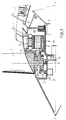
- Figure 1 shows a partial axial section from the front of a turbojet engine comprising a variation of the pitch of the blades of a blower, according to the invention.
- the turbojet engine has a blower comprising a plurality of vanes 1 mounted on a disc driven in rotation by the main shaft 2 of the turbojet, this shaft 2 being itself driven by a gas generator not shown and through a reducer speed 3.
- Each fan blade has a 4 foot can pivot around its longitudinal axis ZZ 'so to vary the pace of dawn.
- the blade pitch variation device includes actuation means for modifying the pitch of the blades and means for locking the root of the blades in a determined position.
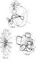
- the means of actuating the change of the pitch of the blades are shown schematically in Figures 2a, 2b and 2c. They have an electric motor having a wound stator 5 integral with the fixed structure 6 of the turbojet engine and a rotor 7 secured to a toothed wheel 8 mounted on bearings and surrounding the main shaft 2.
- the toothed wheel 8 is meshed with pinion sectors 9 fixed on the foot 4 of each blade 1 of the fan, and allows the rotation of the blades around their longitudinal axis ZZ '.
- the maximum angle of rotation of the assembly constituted by a pinion 9, the toothed wheel 8, and the rotor 7 of the electric motor is delimited by two stops fixed 10, 11, as shown schematically in the figure 2b. These two fixed stops correspond to an operation of the direct jet or reverse jet turbojet.
- stops mobiles 12 for example electromagnets, can be provided in addition to the fixed stops, as shown in Figure 2c.
- FIG. 3 represents a schematic example of embodiment movable stops according to the invention.
- additional stops can be arranged on the way angular of a pinion sector 9 associated with a blade root 4, between the two fixed stops 10, 11.
- Each movable stop 20 can be produced by means of a electromagnet 12.
- the electromagnet 12 comprises in a box integral with the shaft 2 of the turbojet engine, a coil the interior of which a movable metal rod 22 is likely to move in translation under the action of a magnetic field.
- a return spring 23 is arranged around the metal rod 22 so as to maintain the rod in the extended position, called end position, when the solenoid 12 is not not powered.
- the position of the movable stopper is checked automatically and continuously through a position detector 24, for example of the end contact type race.
- the blade roots 4 being held mechanically by the wheel toothed via the pinion sectors 9, for get an intermediate vane position just have a movable stop on a single blade so that all the vanes are positioned in this intermediate position.
- the electromagnets 12 for actuating the mobile stops 20 can be powered, without mechanical contact, by through a rotating transformer.
- the electric motor used can be of the magnet type permanent or asynchronous so as to eliminate the problems of friction and wear between the rotating part and the part static.
- the wound stator is fixed and supplied with current alternative by known means not shown, such as by example, an alternator or a generator associated with a rectifier and an inverter, so as to obtain a current alternative with a controlled frequency.
- this rotor can optionally have a closed circuit winding so as to increase the power of the engine and to reduce its dimensions, winding not in connection with the stator winding.
- the blade locking means are shown schematically in Figures 4a and 4b. They include a electromechanical actuator 13, for example an electromagnet, associated with a latch 14 intended to hold the foot 4 of the blades in a determined position.
- the blade root is machined from so as to present several faces corresponding to different possible predetermined positions.
- the actuator electromechanical 13 comprises in a housing integral with the shaft 2 of the reactor, a coil inside which is arranged a metal rod 15 movable in translation.
- the latch 14 is integral with rod 15, when the rod is moves in translation, it drives the latch 14 in its displacement.
- the latch 14 has notches 16 in correspondence with the foot of the blades. In position of locking, the feet of the blades are blocked in the lock notches.
- the position of the lock is checked automatically and continuously through a position detector 17 for example of the end detector type race.
- the blades are all provided with a pinion sector and the pinion sectors all being meshed with the same toothed wheel, the vanes are all mechanically linked one with respect to the other. therefore, the lock does not have to be hold all the dawn feet, just one dawn be maintained to block all others in the same position.
- the lock it is preferable for the lock to maintain two diametrically opposite blades or three regularly spaced blades, as shown in FIG. 4b; In the same way as the electromagnets 12 for actuating the movable stops 20, the actuator 13 is supplied, without mechanical contact, by means of a rotary transformer.
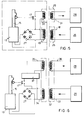
- FIG. 5 represents a first example of a device electric actuator command and control electromechanical, according to the invention.
- the actuator 13 is controlled by through a first rotating transformer 25 comprising a primary winding 18 integral with the structure fixed of the turbojet and a secondary winding 19 fixed on shaft 2 of the turbojet engine.
- a first rotating transformer 25 comprising a primary winding 18 integral with the structure fixed of the turbojet and a secondary winding 19 fixed on shaft 2 of the turbojet engine.
- the primary winding 18 is connected to a electric power supply device 26.
- the secondary winding 19 transmits the electrical power required to control the actuator 13 after rectification in a diode bridge 27.
- the actuator control electric power must be high enough to break its inertia and allow the displacement of the movable rod 15.
- the position of the movable rod 15 of the actuator 13 is signaled by a position detector 17, for example of the limit switch type, constituting an electric switch and transmitted to a position control device 28 via 'a second rotary transformer 29.
- This second rotary transformer 29 comprises a primary winding 30 fixed on the shaft 2 of the turbojet engine and connected to the terminals of the secondary winding 19 of the first rotary transformer 25, and comprises a secondary winding 31 connected at the input of the device of position control 28.
- the switch of the position detector 17 is closed, the second rotary transformer 29 is supplied via the first rotary transformer 25 and transmits the energy received to the position control device 28.
- This first example of an electrical command and control device for an electromechanical actuator is particularly well suited to an environment where temperature constraints are high since it comprises very few electronic components. However, the presence of two rotary transformers has the drawback of increasing the mass and size of the blade locking device.
- FIG. 6 represents a second example of a device electric actuator command and control electromechanical, according to the invention.
- the control of the actuator 13 carried out by means of a rotary transformer 32 comprising two independent windings, each winding comprising a primary winding and a secondary winding.
- the primary 33 and secondary 34 windings are intended to transmit the electrical power, delivered by a supply device 26, necessary for the control of the actuator 13, and to supply, through a position detector 17 of the detector type limit switch, an oscillator 37 at high frequency f and at a low level with respect to the frequency and to the level of the electrical power supply.
- the oscillator output signal is voltage regulated by an internal voltage regulator, not shown.
- the primary 35 and secondary 36 windings have only a few turns and are intended to transmit, to a position control device 28, the signal from the oscillator 37 whose frequency f is representative of the position of the actuator 13.
- This second example of an electrical control and control of an electromechanical actuator present advantageously a reduced mass and size since has only one rotating transformer for transmit simultaneously, by independent windings, an electrical power from a set to a set turning and an electrical signal representative of the position of the actuator.
- an oscillator limits its use to environments where variations in temperature correspond to the operating range of the oscillator.
- the actuator is controlled as follows. During the locking period, the rod 15 of the actuator 13 is in an end-of-travel position, the switch constituting the position detector is open and no signal is transmitted to the control device 28.
- the actuator 13 Under the action of an unlocking command, the actuator 13 is supplied with sufficient electrical power raised to allow movement of the movable rod 15. A magnetic flux is generated inside the coil of the actuator 13 and under the action of magnetic forces, the movable rod 15 moves in translation towards a position of unlocking. During its displacement, the rod actuates the position detector 17 which closes. An electrical signal is then transmitted to the position control device 28.
- FIG. 7 represents a comparative example between the amplitudes of the actuator supply current during the locking and unlocking periods.
- the position of the actuator rod 15 is checked by the transmission of an electrical signal to a position control device 28, when the rod is in the unlocked position. The absence of transmission of the electrical signal indicates an actuator failure.
- position control of the rod 15 of the actuator is carried out by supplying the actuator 13 by an electrical amplitude signal less than that required to move the movable rod 15.
- Figures 8a, 8b, 8c show three examples of rotary transformers according to the invention.
- the rotary transformers comprise a fixed magnetic circuit 80 integral with the fixed structure of the turbojet and separated by axial air gaps 82, 83 of a rotating magnetic circuit 81.
- the rotating magnetic circuit is fixed on the shaft 2 of the turbojet.
- the rotary transformer comprises a winding consisting of a fixed primary winding 84 and a rotary secondary winding 85 making it possible to transmit without contact, an electrical power from a fixed assembly to a rotating assembly.
- the transformer turning has a first winding allowing transmit, without contact, an electrical power from a fixed assembly to a rotating assembly, and a second winding with a few turns (for example one or two turns) independent of the first winding, allowing transmit an electrical signal.
- FIG. 8c In the configuration of FIG. 8c, three transformers turning points are shown. They are arranged one above of the others so as to constitute three windings independent and magnetically isolated from each other. They allow to transmit three electrical powers independently of each other.
- two rotary transformers are required to power on the one hand, the actuator 12 of the mobile stops corresponding to the same intermediate position of the fan blades, and on the other hand, the actuator 13 of the locking system of blades.
- These two rotary transformers each include, a winding to transmit electrical power necessary to control the actuator considered and a winding to transmit an electrical control signal the position of the actuator rod in question.
- the operation of the device for varying the pitch of the blades of a fan is as follows.
- the speed reducer 3 drives the shaft 2 of the turbojet engine and the shaft 2 drives the actuator 13 of the latch 14 and the vanes 1.
- the vanes are held fixed around their longitudinal axis by means of the latch 14 positioned by the actuator 13.
- the vanes 1 drive the toothed wheel 8 and the rotor 7 of the electric motor.
- the stator 5 winding of the electric motor is not supplied electrically.
- the position is modified blades to wedge them on another fixed or mobile stop. is particularly interesting to have three blade positions, two positions being assigned to two modes operating in direct jet, the third position being assigned to a reverse jet operating mode.
- the two direct jet operating modes can by example correspond to a take-off phase and a cruise for which the blades are respectively set on a first extreme fixed stop and on a mobile stop intermediate.
- the reverse jet mode of operation the blades are wedged on a second extreme fixed stop.
- the modification of the position of the blades is carried out according to the time diagram shown in figure 9 for the passage from a direct jet phase to an inverted jet phase.
- FIG. 10 The time diagram of the modification of the position of blades for the passage from a take-off phase to a phase cruise ship is shown in Figure 10. It is similar to that of FIG. 9, however removing the steps (g) and (k) the method of supplying, respectively to cut off the power supply to the actuator 12 of the movable stop 20. This movable stop 20 must indeed remain in place since it is on this stop that the blades must be positioned.
- the power supply to the electric motor is only necessary, in principle, for a few seconds, corresponding to the time necessary to modify the position of the blades.
- the locking system is provided with three levels of security, namely, a lock making it possible to block the blades in rotation about their longitudinal axis, a movable stop preventing the blades from passing from a position of direct jet towards an inverted jet position, and the rotating magnetic field making it possible to block the blades in the event of simultaneous failure of the bolt and of the movable stop.
- the present invention is not limited to the embodiment precisely described, in particular the number of blade positions is not limited and it is possible to have several movable stops each assigned to positions different blades. Furthermore, the locking system can maintain one or more dawn feet depending on the reliability required.
Landscapes
- Engineering & Computer Science (AREA)
- Aviation & Aerospace Engineering (AREA)
- Mechanical Engineering (AREA)
- General Engineering & Computer Science (AREA)
- Structures Of Non-Positive Displacement Pumps (AREA)
Description
L'invention concerne également un procédé de commande du dispositif de variation du pas des aubes d'un rotor d'une turbomachine selon l'une quelconque des revendications précédentes, caractérisé en ce que, pour passer d'une position de verrouillage sur une première butée vers une position de verrouillage sur une deuxième butée, il consiste :
- à effectuer une mesure de la vitesse de rotation de l'arbre de la turbomachine et à contrôler la position du verrou,
- à alimenter le moteur électrique,
- à créer entre le stator et le rotor du moteur électrique, un champ magnétique tournant à une vitesse différente de celle de l'arbre , et impliquant un moment magnétique capable de bloquer les aubes sur la première butée afin de faciliter le déverrouillage et de maintenir les aubes dans la même position pendant la manoeuvre de déverrouillage,
- à alimenter l'actionneur du verrou pour libérer le pied des aubes,
- à modifier la vitesse du champ tournant de manière à inverser le sens du moment magnétique et provoquer la rotation des aubes autour de leur axe longitudinal de la première butée jusqu'à la deuxième butée,
- à couper l'alimentation du système de verrouillage pour verrouiller le pied des aubes sur la deuxième butée,
- à couper l'alimentation du moteur électrique.
- la figure 1 : une coupe partielle axiale de l'avant d'un turboréacteur comportant un dispositif de variation du pas des aubes d'une soufflante, selon l'invention ;
- les figures 2a, 2b, 2c, une vue en perspective et deux vues en coupe du dispositif d'actionnement du changement du pas des aubes, selon l'invention ;
- la figure 3, une vue schématique d'un exemple de réalisation de butées mobiles, selon l'invention ;
- les figures 4a et 4b, deux vues schématiques montrant respectivement la disposition du système de verrouillage des aubes par rapport au disque aubagé et le mécanisme de verrouillage du pied des aubes, selon l'invention ;
- la figure 5, un premier exemple de réalisation d'un dispositif électrique de commande et de contrôle d'un actionneur électromécanique, selon l'invention ;
- la figure 6, un deuxième exemple de réalisation d'un dispositif électrique de commande et de contrôle d'un actionneur électromécanique, selon l'invention ;
- la figure 7, un exemple comparatif entre les amplitudes du courant d'alimentation de l'actionneur électromécanique pendant les périodes de verrouillage et de déverrouillage ;
- les figures 8a, 8b, 8c, trois exemples de transformateurs tournants, selon l'invention ;
- la figure 9, un exemple de diagramme de fonctionnement du dispositif de variation du pas des aubes lors d'un passage d'une phase de jet direct vers une phase de jet inversé.
- la figure 10, un exemple de diagramme de fonctionnement du dispositif de variation du pas des aubes lors d'un passage d'une phase de décollage vers une phase de croisière ;
De la même façon que les électro-aimants 12 d'actionnement des butées mobiles 20, l'actionneur 13 est alimenté, sans contact mécanique, par l'intermédiaire d'un transformateur tournant.
Ce premier exemple de dispositif électrique de commande et de contrôle d'un actionneur électromécanique est particulièrement bien adapté à un environnement où les contraintes en température sont importantes puisqu'il comporte très peu de composants électroniques. Cependant, la présence de deux transformateurs tournants présente l'inconvénient d'augmenter la masse et l'encombrement du dispositif de verrouillage des aubes.
Les bobinages primaire 33 et secondaire 34 sont destinés à transmettre la puissance électrique, délivrée par un dispositif d'alimentation 26, nécessaire à la commande de l'actionneur 13, et à alimenter, au travers d'un détecteur de position 17 du type détecteur de fin de course, un oscillateur 37 à fréquence f élevée et à faible niveau par rapport à la fréquence et au niveau de la puissance électrique d'alimentation. Le signal de sortie de l'oscillateur est régulé en tension par un régulateur de tension interne non représenté. Les bobinages primaire 35 et secondaire 36 ne comportent que quelques spires et sont destinés à transmettre, à un dispositif de contrôle de position 28, le signal issu de l'oscillateur 37 dont la fréquence f est représentative de la position de l'actionneur 13.
Pendant la période de verrouillage, la tige 15 de l'actionneur 13 est dans une position de fin de course, l'interrupteur constituant le détecteur de position est ouvert et aucun signal n'est transmis vers le dispositif de contrôle 28.
Pendant la période de déverrouillage, le contrôle de la position de la tige 15 de l'actionneur est effectué par la transmission d'un signal électrique à un dispositif de contrôle de position 28, lorsque la tige est bien dans la position de déverrouillage. L'absence de transmission du signal électrique indique une panne de l'actionneur.
Dans la configuration de la figure 8a, le transformateur tournant comporte un enroulement constitué d'un bobinage primaire fixe 84 et d'un bobinage secondaire tournant 85 permettant de transmettre sans contact, une puissance électrique d'un ensemble fixe à un ensemble tournant.
Lorsque les aubes sont dans une position déterminée en jet direct ou en jet inversé et calées sur une butée fixe ou mobile, le réducteur de vitesse 3 entraíne l'arbre 2 du turboréacteur et l'arbre 2 entraíne l'actionneur 13 du verrou 14 et les aubes 1. Les aubes sont maintenues fixes autour de leur axe longitudinal par l'intermédiaire du verrou 14 positionné par l'actionneur 13. Les aubes 1 entraínent la roue dentée 8 et le rotor 7 du moteur électrique. Le bobinage du stator 5 du moteur électrique n'est pas alimenté électriquement.
De cette manière, le système de verrouillage est muni de trois niveaux de sécurité, à savoir, un verrou permettant de bloquer les aubes en rotation autour de leur axe longitudinal, une butée mobile empêchant les aubes de passer d'une position de jet direct vers une position de jet inversé, et le champ magnétique tournant permettant de bloquer les aubes en cas de ruptures simultanées du verrou et de la butée mobile.
Claims (14)
- Dispositif de variation du pas des aubes d'un rotor d'une turbomachine, les aubes étant montées sur un disque entraíné en rotation par un arbre de la turbomachine et ayant chacune un pied pouvant pivoter autour d'un axe longitudinal de l'aube, caractérisé en ce qu'il comporte des moyens d'actionnement du changement du pas des aubes et des moyens de verrouillage du pied des aubes, les moyens d'actionnement comportant un moteur électrique ayant un stator bobiné fixe (5) et un rotor (7) fixé sur l'arbre (2) de la turbomachine, le rotor (7) ne possédant aucune liaison électrique avec le stator et étant solidaire d'une roue dentée (8) sur laquelle sont engrenés des secteurs de pignons (9) solidaires du pied (4) de chaque aube (1), les moyens de verrouillage comportant un actionneur électromécanique (13) solidaire de l'arbre (2) et alimenté en énergie électrique par l'intermédiaire d'un transformateur tournant (25).
- Dispositif selon la revendication 1, caractérisé en ce que l'ensemble constitué par un pignon (9), la roue dentée (8), et le rotor (7) du moteur électrique a un débattement angulaire maximal délimité par deux butées fixes (10,11), ces butées fixes correspondant à deux positions d'aube extrêmes.
- Dispositif selon la revendication 2, caractérisé en ce qu'il comporte au moins une butée mobile (20) correspondant à au moins une position d'aube intermédiaire entre les deux positions extrêmes.
- Dispositif selon la revendication 3, caractérisé en ce que la butée mobile (20) est un électro-aimant (12) alimenté par l'intermédiaire d'un transformateur tournant.
- Dispositif selon la revendication 4, caractérisé en ce que l'électro-aimant (12) constituant la butée mobile (20) comporte dans un boítier solidaire de l'arbre (2), une bobine à l'intérieur de laquelle une tige métallique (22) est mobile en translation.
- Dispositif selon la revendication 5, caractérisé en ce que un ressort de rappel est disposé autour de la tige (22).
- Dispositif selon l'une quelconque des revendications précédentes, caractérisé en ce que l'actionneur électromécanique (13) est associé à un verrou (14) destiné à maintenir le pied des aubes dans une position déterminée et en ce qu'il comporte, dans un boítier solidaire de l'arbre (2), une bobine à l'intérieur de laquelle est disposée une tige métallique (15) mobile en translation, la tige (15) étant solidaire du verrou (14).
- Dispositif selon la revendication 7, caractérisé en ce qu'il comporte en outre des moyens de contrôle de la position de la tige (22) de l'électro-aimant (12) constituant la butée mobile (20) et/ou des moyens de contrôle de la position de la tige (15) de l'actionneur (13) du verrou (14), les moyens de contrôle de position comportant pour chacune des tiges (22, 15), un détecteur de position (17) associé à un dispositif de contrôle de position (28) alimenté en énergie électrique par l'intermédiaire d'au moins un transformateur tournant lorsque la tige (22,15) est rétractée.
- Dispositif selon la revendication 8, caractérisé en ce que le détecteur de position (17) est un contact de fin de course.
- Dispositif selon la revendication 9, caractérisé en ce que l'alimentation en énergie électrique du dispositif de contrôle de position (28) est effectuée par l'intermédiaire de deux transformateurs tournants (25, 29), le premier transformateur tournant (25) comportant un bobinage primaire fixe (18) relié à un dispositif d'alimentation en énergie électrique (26) et un bobinage secondaire (19) fixé sur l'arbre (2), le deuxième transformateur tournant (29) comportant un bobinage primaire (30) fixé sur l'arbre (2) et relié par l'intermédiaire du détecteur de position (17) aux boites du bobinage secondaire (19) du premier transformateur tournant (25), et un bobinage secondaire (31) relié au dispositif de contrôle de position (28).
- Dispositif selon la revendication 9, caractérisé en ce que l'alimentation en énergie électrique du dispositif de contrôle de position (28) est effectuée par l'intermédiaire d'un seul transformateur tournant (32) comportant deux enroulements indépendants, le premier enroulement comportant un bobinage primaire (33) relié à un dispositif d'alimentation en énergie électrique (26) et un bobinage secondaire (34) relié à un oscillateur (37) par l'intermédiaire du détecteur de position (17), le deuxième enroulement n'ayant que quelques spires et comportant un bobinage primaire (35) relié à l'oscillateur (37) et un bobinage secondaire relié au dispositif de contrôle de position (28).
- Procédé de commande du dispositif de variation du pas des aubes d'un rotor d'une turbomachine selon l'une quelconque des revendications précédentes, caractérisé en ce que, pour passer d'une position de verrouillage sur une première butée vers une position de verrouillage sur une deuxième butée, il consiste :à effectuer une mesure de la vitesse de rotation de l'arbre (2) de la turbomachine et à contrôler la position du verrou (14),à alimenter le moteur électrique,à créer entre le stator (5) et le rotor (7) du moteur électrique, un champ magnétique tournant à une vitesse différente de celle de l'arbre (2), et impliquant un moment magnétique capable de bloquer les aubes sur la première butée afin de faciliter le déverrouillage et de maintenir les aubes dans la même position pendant la manoeuvre de déverrouillage,à alimenter l'actionneur (13) du verrou (14) pour libérer le pied (4) des aubes (1),à modifier la vitesse du champ tournant de manière à inverser le sens du moment magnétique et provoquer la rotation des aubes autour de leur axe longitudinal de la première butée jusqu'à la deuxième butée,à couper l'alimentation du système de verrouillage pour verrouiller le pied des aubes sur la deuxième butée,à couper l'alimentation du moteur électrique.
- Procédé selon la revendication 12, caractérisé en ce qu'il consiste en outre pour passer d'une position de verrouillage sur la première butée fixe vers une position de verrouillage sur la deuxième butée fixe :à contrôler la position de la butée mobile (20) avant d'alimenter le moteur électrique,à alimenter l'actionneur (12) de la butée mobile (20) avant d'alimenter l'actionneur (13) du verrou (14),à couper l'alimentation de la butée mobile (20) après la rotation des aubes sur la deuxième butée fixe de manière à interdire le retour intempestif des aubes dans la position initiale en cas de rupture du système de verrouillage.
- Procédé selon l'une quelconque des revendications 12 ou 13, caractérisé en ce qu'il consiste, en cas de pannes simultanées du verrou (14) et des butées mobiles (20), à alimenter le moteur électrique de manière à créer un champ magnétique tournant pour bloquer en permanence les aubes sur une butée mécanique.
Applications Claiming Priority (2)
| Application Number | Priority Date | Filing Date | Title |
|---|---|---|---|
| FR9313409A FR2712250B1 (fr) | 1993-11-10 | 1993-11-10 | Procédé et dispositif de commande de variation du pas des pales d'un rotor. |
| FR9313409 | 1993-11-10 |
Publications (2)
| Publication Number | Publication Date |
|---|---|
| EP0652154A1 EP0652154A1 (fr) | 1995-05-10 |
| EP0652154B1 true EP0652154B1 (fr) | 1998-07-15 |
Family
ID=9452718
Family Applications (1)
| Application Number | Title | Priority Date | Filing Date |
|---|---|---|---|
| EP94402530A Expired - Lifetime EP0652154B1 (fr) | 1993-11-10 | 1994-11-09 | Procédé et dispositif de variation du pas des pales d'un rotor |
Country Status (10)
| Country | Link |
|---|---|
| US (1) | US5595474A (fr) |
| EP (1) | EP0652154B1 (fr) |
| JP (1) | JP3032440B2 (fr) |
| CA (1) | CA2135469C (fr) |
| DE (1) | DE69411672T2 (fr) |
| FR (1) | FR2712250B1 (fr) |
| RU (1) | RU2107194C1 (fr) |
| UA (1) | UA26462C2 (fr) |
| WO (1) | WO1995013215A1 (fr) |
| ZA (1) | ZA948876B (fr) |
Cited By (1)
| Publication number | Priority date | Publication date | Assignee | Title |
|---|---|---|---|---|
| CN113007133A (zh) * | 2019-12-19 | 2021-06-22 | 北汽福田汽车股份有限公司 | 风扇及散热模块、车辆 |
Families Citing this family (65)
| Publication number | Priority date | Publication date | Assignee | Title |
|---|---|---|---|---|
| DE4446623A1 (de) * | 1994-12-24 | 1996-06-27 | Klein Schanzlin & Becker Ag | Propellerverstelleinrichtung mit Synchronelement |
| RU2108268C1 (ru) * | 1996-10-17 | 1998-04-10 | Йелстаун Корпорейшн Н.В. | Система и способ управления воздушным винтом изменяемого шага с обратной связью |
| US6379109B1 (en) | 2000-05-12 | 2002-04-30 | Roy F. Senior, Jr. | Method and apparatus for detecting and removing obstructions in mechanical aerators |
| US6476534B1 (en) | 2000-08-08 | 2002-11-05 | General Dynamics Advanced Technology Systems, Inc. | Permanent magnet phase-control motor |
| CN1277052C (zh) * | 2000-11-14 | 2006-09-27 | 阿洛伊斯·沃本 | 风能装置 |
| WO2003035470A1 (fr) * | 2001-10-22 | 2003-05-01 | Lamont John S | Aeronef |
| FR2831225B1 (fr) * | 2001-10-24 | 2004-01-02 | Snecma Moteurs | Dispositif electrohydraulique de changement de pas d'helice |
| US6672835B1 (en) | 2003-05-19 | 2004-01-06 | Arthur C. Hughes | Method and apparatus for self-contained variable pitch and/or constant speed propeller including provisions for feathering and reverse pitch operation |
| CA2459200A1 (fr) | 2004-02-27 | 2005-08-27 | John S. Lamont | Aeronef |
| US20050226727A1 (en) * | 2004-03-03 | 2005-10-13 | Dennis Brian D | Methods and systems for controlling the pitch of a propeller |
| US7513320B2 (en) * | 2004-12-16 | 2009-04-07 | Tdy Industries, Inc. | Cemented carbide inserts for earth-boring bits |
| US7901185B2 (en) * | 2007-02-21 | 2011-03-08 | United Technologies Corporation | Variable rotor blade for gas turbine engine |
| US7939958B2 (en) * | 2007-06-01 | 2011-05-10 | Bill Todorof | Direct drive wind turbine and blade assembly |
| FR2922265B1 (fr) * | 2007-10-12 | 2013-11-22 | Snecma | Turboreacteur incorporant un generateur de courant electrique. |
| RU2390659C1 (ru) * | 2008-12-22 | 2010-05-27 | Государственное образовательное учреждение высшего профессионального образования "Воронежский государственный технический университет" | Устройство для изменения углов установки рабочих лопаток вентилятора |
| US9200594B2 (en) * | 2009-02-27 | 2015-12-01 | Snecma | Gas turbine engine having fan blades of adjustable pitch with cyclic setting |
| FR2951696B1 (fr) * | 2009-10-22 | 2011-12-23 | Snecma | Systeme pour faire varier l'incidence des pales d'une helice de turbomachine pour aeronef, utilisant un moteur electrique sans balai |
| FR2956854B1 (fr) * | 2010-03-01 | 2012-08-17 | Snecma | Dispositif de commande de l'orientation des pales de soufflante d'un turbopropulseur par contrepoids. |
| FR2959481B1 (fr) * | 2010-04-30 | 2013-02-08 | Hispano Suiza Sa | Actionnement des pales d'une soufflante non carenee |
| FR2961176B1 (fr) * | 2010-06-15 | 2012-08-03 | Hispano Suiza Sa | Alimentation electrique des equipements portes par le rotor d'un moteur d'aeronef |
| DE102010039394A1 (de) * | 2010-08-17 | 2012-02-23 | Siemens Aktiengesellschaft | Verstellpropeller oder -repeller |
| FR2964944B1 (fr) * | 2010-09-20 | 2013-05-24 | Snecma | Dispositif d'etancheite a soufflet pour la traversee de cloison par une biellette d'un systeme de commande de l'orientation des pales de soufflante d'un turbopropulseur |
| RU2479753C2 (ru) * | 2011-07-07 | 2013-04-20 | Общество с ограниченной ответственностью "Газхолодтехника" | Способ автоматического управления частотой вращения рабочих колес вентиляторов |
| US9470153B2 (en) * | 2011-10-05 | 2016-10-18 | United Technologies Corporation | Combined pump system for engine TMS AOC reduction and ECS loss elimination |
| FR2983235B1 (fr) * | 2011-11-24 | 2018-04-13 | Safran Electrical & Power | Systeme mecanique tournant a actionnement sans contact |
| ITTO20111113A1 (it) * | 2011-12-05 | 2013-06-06 | Wilic Sarl | Impianto eolico per la generazione di energia elettrica |
| US20130280078A1 (en) * | 2012-04-23 | 2013-10-24 | Kollmorgen Corporation | Wind Turbine Blade Pitch Redundant Safety Arrangement |
| FR2997245B1 (fr) * | 2012-10-24 | 2016-01-15 | Hispano Suiza Sa | Systeme electromecanique d'actionnement et/ou generation, comprenant une isolation electrique entre la source electrique et le consommateur |
| WO2015053930A1 (fr) * | 2013-10-11 | 2015-04-16 | Unison Industries, Llc | Procédé et appareil permettant de commander un turbopropulseur |
| CN104863881B (zh) * | 2014-02-21 | 2018-10-23 | 南京中兴新软件有限责任公司 | 电子设备中风扇转速的控制方法及装置 |
| US10436056B2 (en) | 2015-06-23 | 2019-10-08 | General Electric Company | Relative position measurement |
| US10436151B2 (en) * | 2015-11-17 | 2019-10-08 | General Electric Company | Modular fan for a gas turbine engine |
| US10830066B2 (en) * | 2016-01-05 | 2020-11-10 | Safran Aircraft Engines | Low-pitch variable-setting fan of a turbine engine |
| US10288087B2 (en) * | 2016-03-24 | 2019-05-14 | United Technologies Corporation | Off-axis electric actuation for variable vanes |
| US10443431B2 (en) * | 2016-03-24 | 2019-10-15 | United Technologies Corporation | Idler gear connection for multi-stage variable vane actuation |
| US10329946B2 (en) * | 2016-03-24 | 2019-06-25 | United Technologies Corporation | Sliding gear actuation for variable vanes |
| US10294813B2 (en) | 2016-03-24 | 2019-05-21 | United Technologies Corporation | Geared unison ring for variable vane actuation |
| US10443430B2 (en) * | 2016-03-24 | 2019-10-15 | United Technologies Corporation | Variable vane actuation with rotating ring and sliding links |
| US10190599B2 (en) | 2016-03-24 | 2019-01-29 | United Technologies Corporation | Drive shaft for remote variable vane actuation |
| US10301962B2 (en) | 2016-03-24 | 2019-05-28 | United Technologies Corporation | Harmonic drive for shaft driving multiple stages of vanes via gears |
| US10458271B2 (en) | 2016-03-24 | 2019-10-29 | United Technologies Corporation | Cable drive system for variable vane operation |
| US10415596B2 (en) | 2016-03-24 | 2019-09-17 | United Technologies Corporation | Electric actuation for variable vanes |
| US10329947B2 (en) | 2016-03-24 | 2019-06-25 | United Technologies Corporation | 35Geared unison ring for multi-stage variable vane actuation |
| BE1024492B1 (fr) * | 2016-08-12 | 2018-03-12 | Safran Aero Boosters S.A. | Aube a orientation variable de compresseur de turbomachine axiale |
| US10801339B2 (en) | 2017-07-11 | 2020-10-13 | General Electric Company | Aircraft gas turbine engine variable fan blade mechanism |
| CN111065577A (zh) * | 2017-08-23 | 2020-04-24 | 维曼机器人股份有限公司 | 驱动机构 |
| CN107902075B (zh) * | 2017-11-09 | 2020-11-27 | 中国航发湖南动力机械研究所 | 静态变距螺旋桨 |
| FR3075257B1 (fr) * | 2017-12-14 | 2021-02-19 | Safran Aircraft Engines | Dispositif de reglage du calage d'une helice |
| EP3502438A1 (fr) * | 2017-12-19 | 2019-06-26 | Siemens Aktiengesellschaft | Commande de compresseur |
| FR3087232B1 (fr) * | 2018-10-12 | 2021-06-25 | Safran Aircraft Engines | Turbomachine comprenant un rotor portant des pales a calage variable |
| US11345469B2 (en) * | 2018-11-19 | 2022-05-31 | Joby Aero, Inc. | Aerial vehicle using motor pulse-induced cyclic control |
| US10934880B1 (en) | 2019-09-04 | 2021-03-02 | The Boeing Company | Electrical generation from turbine engines |
| US11362567B2 (en) | 2020-01-16 | 2022-06-14 | The Boeing Company | Electrical power generation from turbine engines |
| AT523262B1 (de) * | 2020-01-29 | 2021-07-15 | Manuel Schleiffelder Mag | Vorrichtung zur Verstellung der Neigung von Rotorblättern eines Rotors |
| EP3882133A1 (fr) | 2020-03-16 | 2021-09-22 | Ratier-Figeac SAS | Mécanisme d'actionnement de pas de pale |
| FR3108670B1 (fr) | 2020-03-31 | 2022-04-01 | Safran Aircraft Engines | Module de soufflante pour un banc d’essai de turbomachine d’aeronef |
| US11193426B2 (en) | 2020-04-16 | 2021-12-07 | The Boeing Company | Electrically geared turbofan |
| US20210347465A1 (en) * | 2020-05-11 | 2021-11-11 | Hamilton Sundstrand Corporation | Wireless power transformation for rotating propellers |
| PL435034A1 (pl) | 2020-08-20 | 2022-02-21 | General Electric Company Polska Spółka Z Ograniczoną Odpowiedzialnością | Zespoły silnika napędowego zapewniające dostęp do elementów składowych w komorach pędnych |
| KR20220082733A (ko) | 2020-12-10 | 2022-06-17 | 더 보잉 컴파니 | 다이렉트 드라이브 전기적-기어식 터보팬 |
| JP7323236B2 (ja) * | 2021-02-20 | 2023-08-08 | 西安亜能電気有限責任公司 | 電力システム上のファンに用いられる監視コンポーネント、監視装置及び監視モデル |
| CN113682462A (zh) * | 2021-09-18 | 2021-11-23 | 上海交通大学 | 推进装置及其可调进口预旋导叶电驱动涵道风扇推进系统 |
| CN113955084B (zh) * | 2021-12-22 | 2022-03-25 | 四川承天翼航空科技有限公司 | 旋翼变距控制系统、方法、同步/不同步变距控制方法 |
| CN115123519B (zh) * | 2022-08-30 | 2022-11-22 | 沃飞长空科技(成都)有限公司 | 一种可变距的旋翼装置及飞行器 |
| US12388322B2 (en) * | 2023-03-24 | 2025-08-12 | Rolls-Royce North American Technologies, Inc. | Electric generator behind fan in turbine engine |
Family Cites Families (13)
| Publication number | Priority date | Publication date | Assignee | Title |
|---|---|---|---|---|
| US2370135A (en) * | 1941-09-25 | 1945-02-27 | Engineering & Res Corp | Variable pitch propeller |
| FR890641A (fr) * | 1942-10-05 | 1944-02-14 | Système pour la transmission d'énergie électrique entre une partie fixe et une partie mobile, mécanismes et machines comportant application de ce système | |
| US2612228A (en) * | 1945-07-03 | 1952-09-30 | Fairey Aviat Co Ltd | Electrically driven propeller pitch change system |
| US2632516A (en) * | 1946-11-26 | 1953-03-24 | United Aircraft Corp | Automatic control for reversing propellers |
| US3044558A (en) * | 1960-01-05 | 1962-07-17 | Curtiss Wright Corp | Propeller pitch control system |
| US3900274A (en) * | 1974-06-25 | 1975-08-19 | Gen Electric | Remote controlled actuation system for the rotor of a gas turbine engine |
| US4591313A (en) * | 1983-12-30 | 1986-05-27 | The Boeing Company | Propeller pitch control system and apparatus |
| US5282719A (en) * | 1991-05-13 | 1994-02-01 | Alliedsignal Inc. | Quad mode fan pitch actuation system for a gas turbine engine |
| US5281094A (en) * | 1991-05-13 | 1994-01-25 | Alliedsignal Inc | Electromechanical apparatus for varying blade of variable-pitch fan blades |
| US5205712A (en) * | 1991-05-13 | 1993-04-27 | Allied-Signal Inc. | Variable pitch fan gas turbine engine |
| US5183387A (en) * | 1992-01-03 | 1993-02-02 | Allied-Signal, Inc. | Fault-tolerant apparatus for controlling blade pitch |
| FR2709618B1 (fr) * | 1993-07-28 | 1995-09-29 | Hispano Suiza Sa | Dispositif de transmission de signaux électriques de puissance à un ensemble tournant. |
| US5451141A (en) * | 1993-12-23 | 1995-09-19 | United Technologies Corporation | Propeller pitch change machanism with inductive brake and motor |
-
1993
- 1993-11-10 FR FR9313409A patent/FR2712250B1/fr not_active Expired - Fee Related
-
1994
- 1994-11-09 ZA ZA948876A patent/ZA948876B/xx unknown
- 1994-11-09 UA UA95073144A patent/UA26462C2/uk unknown
- 1994-11-09 RU RU95121938A patent/RU2107194C1/ru not_active IP Right Cessation
- 1994-11-09 EP EP94402530A patent/EP0652154B1/fr not_active Expired - Lifetime
- 1994-11-09 CA CA002135469A patent/CA2135469C/fr not_active Expired - Fee Related
- 1994-11-09 DE DE69411672T patent/DE69411672T2/de not_active Expired - Fee Related
- 1994-11-09 WO PCT/FR1994/001308 patent/WO1995013215A1/fr not_active Ceased
- 1994-11-10 JP JP6303020A patent/JP3032440B2/ja not_active Expired - Fee Related
-
1996
- 1996-04-04 US US08/627,394 patent/US5595474A/en not_active Expired - Fee Related
Cited By (1)
| Publication number | Priority date | Publication date | Assignee | Title |
|---|---|---|---|---|
| CN113007133A (zh) * | 2019-12-19 | 2021-06-22 | 北汽福田汽车股份有限公司 | 风扇及散热模块、车辆 |
Also Published As
| Publication number | Publication date |
|---|---|
| WO1995013215A1 (fr) | 1995-05-18 |
| JPH07197852A (ja) | 1995-08-01 |
| US5595474A (en) | 1997-01-21 |
| EP0652154A1 (fr) | 1995-05-10 |
| DE69411672T2 (de) | 1998-12-24 |
| ZA948876B (en) | 1995-07-31 |
| CA2135469C (fr) | 2003-04-22 |
| FR2712250A1 (fr) | 1995-05-19 |
| RU2107194C1 (ru) | 1998-03-20 |
| CA2135469A1 (fr) | 1995-05-11 |
| UA26462C2 (uk) | 1999-08-30 |
| DE69411672D1 (de) | 1998-08-20 |
| JP3032440B2 (ja) | 2000-04-17 |
| FR2712250B1 (fr) | 1995-12-29 |
Similar Documents
| Publication | Publication Date | Title |
|---|---|---|
| CA2135469C (fr) | Procede et dispositif de commande de variation du pas des pales d'un rotor | |
| EP1115977B1 (fr) | Eolienne avec rotors contrarotatifs | |
| EP0843089B2 (fr) | Système de commande électrique pour inverseur de poussée de turboréacteur | |
| CA2418788C (fr) | Dispositif d'accrochage, notamment pour l'accrochage d'un train d'atterrissage d'aeronef ou d'une trappe de train d'atterrissage d'aeronef, et procede de fonctionnement dudit dispositif | |
| FR2553596A1 (fr) | Systeme d'actionnement d'helice de moteur | |
| EP1306558A1 (fr) | Dispositif électrohydraulique de changement de pas d'hélice | |
| CA2877899C (fr) | Dispositif de ventilation et d'alimentation electrique d'un calculateur de moteur d'aeronef | |
| CA3197202A1 (fr) | Turbomachine a turbine libre comprenant des machines electriques assistant un generateur de gaz et une turbine libre | |
| EP2419619B1 (fr) | Système de contrôle pour nacelle de turboréacteur | |
| FR3050433A1 (fr) | Systeme simplifie d'actionnement de pas pour une helice de turbomachine | |
| WO1994000858A1 (fr) | Actionneur electromecanique pour commander un modulateur de debit du type volet pivotant a l'interieur d'une canalisation | |
| WO2017182734A1 (fr) | Système d'actionnement de pas pour une hélice de turbomachine | |
| EP3394408B1 (fr) | Mécanisme de transmission comprenant un organe d'accouplement, turbomachine équipée d'un tel mécanisme et procédé de fonctionnement dudit mécanisme | |
| CA2854991A1 (fr) | Systeme mecanique tournant a actionnement sans contact | |
| FR3060523A1 (fr) | Systeme d'actionnement electromecanique de pas pour une helice de turbomachine | |
| FR3050431A1 (fr) | Systeme d'actionnement simplifie de pas pour une helice de turbomachine | |
| FR2596101A1 (fr) | Systeme de commande de moteur a air | |
| EP1653593B1 (fr) | Moteur électromécanique à double sortie | |
| FR3010455A1 (fr) | Dispositif d'entrainement d'actionneurs pour inverseur de poussee permettant selectivement un entrainement motorise ou manuel | |
| EP0642209A1 (fr) | Dispositif de démarrage de turbine, notamment de turbine à gaz | |
| FR3060526A1 (fr) | Systeme d'actionnement electromecanique de pas pour une helice de turbomachine | |
| FR3060525A1 (fr) | Systeme d'actionnement electromecanique de pas pour une helice de turbomachine | |
| WO2024246467A1 (fr) | Module de soufflante pour une turbomachine d'aeronef | |
| FR3167180A1 (fr) | Module de soufflante pour une turbomachine d’aeronef | |
| FR3165864A1 (fr) | Dispositif d’alimentation électrique d’un système de dégivrage |
Legal Events
| Date | Code | Title | Description |
|---|---|---|---|
| PUAI | Public reference made under article 153(3) epc to a published international application that has entered the european phase |
Free format text: ORIGINAL CODE: 0009012 |
|
| 17P | Request for examination filed |
Effective date: 19941126 |
|
| AK | Designated contracting states |
Kind code of ref document: A1 Designated state(s): DE FR GB IT |
|
| 17Q | First examination report despatched |
Effective date: 19970528 |
|
| GRAG | Despatch of communication of intention to grant |
Free format text: ORIGINAL CODE: EPIDOS AGRA |
|
| GRAG | Despatch of communication of intention to grant |
Free format text: ORIGINAL CODE: EPIDOS AGRA |
|
| GRAH | Despatch of communication of intention to grant a patent |
Free format text: ORIGINAL CODE: EPIDOS IGRA |
|
| GRAH | Despatch of communication of intention to grant a patent |
Free format text: ORIGINAL CODE: EPIDOS IGRA |
|
| RAP1 | Party data changed (applicant data changed or rights of an application transferred) |
Owner name: HISPANO-SUIZA |
|
| GRAA | (expected) grant |
Free format text: ORIGINAL CODE: 0009210 |
|
| AK | Designated contracting states |
Kind code of ref document: B1 Designated state(s): DE FR GB IT |
|
| ITF | It: translation for a ep patent filed | ||
| GBT | Gb: translation of ep patent filed (gb section 77(6)(a)/1977) |
Effective date: 19980723 |
|
| REF | Corresponds to: |
Ref document number: 69411672 Country of ref document: DE Date of ref document: 19980820 |
|
| PLBE | No opposition filed within time limit |
Free format text: ORIGINAL CODE: 0009261 |
|
| STAA | Information on the status of an ep patent application or granted ep patent |
Free format text: STATUS: NO OPPOSITION FILED WITHIN TIME LIMIT |
|
| 26N | No opposition filed | ||
| REG | Reference to a national code |
Ref country code: GB Ref legal event code: IF02 |
|
| PGFP | Annual fee paid to national office [announced via postgrant information from national office to epo] |
Ref country code: FR Payment date: 20031020 Year of fee payment: 10 |
|
| PGFP | Annual fee paid to national office [announced via postgrant information from national office to epo] |
Ref country code: GB Payment date: 20031105 Year of fee payment: 10 |
|
| PGFP | Annual fee paid to national office [announced via postgrant information from national office to epo] |
Ref country code: DE Payment date: 20040130 Year of fee payment: 10 |
|
| PG25 | Lapsed in a contracting state [announced via postgrant information from national office to epo] |
Ref country code: GB Free format text: LAPSE BECAUSE OF NON-PAYMENT OF DUE FEES Effective date: 20041109 |
|
| PG25 | Lapsed in a contracting state [announced via postgrant information from national office to epo] |
Ref country code: DE Free format text: LAPSE BECAUSE OF NON-PAYMENT OF DUE FEES Effective date: 20050601 |
|
| GBPC | Gb: european patent ceased through non-payment of renewal fee |
Effective date: 20041109 |
|
| PG25 | Lapsed in a contracting state [announced via postgrant information from national office to epo] |
Ref country code: FR Free format text: LAPSE BECAUSE OF NON-PAYMENT OF DUE FEES Effective date: 20050729 |
|
| REG | Reference to a national code |
Ref country code: FR Ref legal event code: ST |
|
| PG25 | Lapsed in a contracting state [announced via postgrant information from national office to epo] |
Ref country code: IT Free format text: LAPSE BECAUSE OF NON-PAYMENT OF DUE FEES;WARNING: LAPSES OF ITALIAN PATENTS WITH EFFECTIVE DATE BEFORE 2007 MAY HAVE OCCURRED AT ANY TIME BEFORE 2007. THE CORRECT EFFECTIVE DATE MAY BE DIFFERENT FROM THE ONE RECORDED. Effective date: 20051109 |