EP0652145B1 - Electronic braking control system - Google Patents
Electronic braking control system Download PDFInfo
- Publication number
- EP0652145B1 EP0652145B1 EP94308104A EP94308104A EP0652145B1 EP 0652145 B1 EP0652145 B1 EP 0652145B1 EP 94308104 A EP94308104 A EP 94308104A EP 94308104 A EP94308104 A EP 94308104A EP 0652145 B1 EP0652145 B1 EP 0652145B1
- Authority
- EP
- European Patent Office
- Prior art keywords
- wheel
- valve
- electronic control
- brake pressure
- control unit
- Prior art date
- Legal status (The legal status is an assumption and is not a legal conclusion. Google has not performed a legal analysis and makes no representation as to the accuracy of the status listed.)
- Expired - Lifetime
Links
Images


Classifications
-
- B—PERFORMING OPERATIONS; TRANSPORTING
- B60—VEHICLES IN GENERAL
- B60T—VEHICLE BRAKE CONTROL SYSTEMS OR PARTS THEREOF; BRAKE CONTROL SYSTEMS OR PARTS THEREOF, IN GENERAL; ARRANGEMENT OF BRAKING ELEMENTS ON VEHICLES IN GENERAL; PORTABLE DEVICES FOR PREVENTING UNWANTED MOVEMENT OF VEHICLES; VEHICLE MODIFICATIONS TO FACILITATE COOLING OF BRAKES
- B60T8/00—Arrangements for adjusting wheel-braking force to meet varying vehicular or ground-surface conditions, e.g. limiting or varying distribution of braking force
- B60T8/32—Arrangements for adjusting wheel-braking force to meet varying vehicular or ground-surface conditions, e.g. limiting or varying distribution of braking force responsive to a speed condition, e.g. acceleration or deceleration
- B60T8/34—Arrangements for adjusting wheel-braking force to meet varying vehicular or ground-surface conditions, e.g. limiting or varying distribution of braking force responsive to a speed condition, e.g. acceleration or deceleration having a fluid pressure regulator responsive to a speed condition
- B60T8/36—Arrangements for adjusting wheel-braking force to meet varying vehicular or ground-surface conditions, e.g. limiting or varying distribution of braking force responsive to a speed condition, e.g. acceleration or deceleration having a fluid pressure regulator responsive to a speed condition including a pilot valve responding to an electromagnetic force
- B60T8/3615—Electromagnetic valves specially adapted for anti-lock brake and traction control systems
- B60T8/3675—Electromagnetic valves specially adapted for anti-lock brake and traction control systems integrated in modulator units
-
- B—PERFORMING OPERATIONS; TRANSPORTING
- B60—VEHICLES IN GENERAL
- B60T—VEHICLE BRAKE CONTROL SYSTEMS OR PARTS THEREOF; BRAKE CONTROL SYSTEMS OR PARTS THEREOF, IN GENERAL; ARRANGEMENT OF BRAKING ELEMENTS ON VEHICLES IN GENERAL; PORTABLE DEVICES FOR PREVENTING UNWANTED MOVEMENT OF VEHICLES; VEHICLE MODIFICATIONS TO FACILITATE COOLING OF BRAKES
- B60T13/00—Transmitting braking action from initiating means to ultimate brake actuator with power assistance or drive; Brake systems incorporating such transmitting means, e.g. air-pressure brake systems
- B60T13/10—Transmitting braking action from initiating means to ultimate brake actuator with power assistance or drive; Brake systems incorporating such transmitting means, e.g. air-pressure brake systems with fluid assistance, drive, or release
- B60T13/66—Electrical control in fluid-pressure brake systems
- B60T13/68—Electrical control in fluid-pressure brake systems by electrically-controlled valves
- B60T13/683—Electrical control in fluid-pressure brake systems by electrically-controlled valves in pneumatic systems or parts thereof
-
- B—PERFORMING OPERATIONS; TRANSPORTING
- B60—VEHICLES IN GENERAL
- B60T—VEHICLE BRAKE CONTROL SYSTEMS OR PARTS THEREOF; BRAKE CONTROL SYSTEMS OR PARTS THEREOF, IN GENERAL; ARRANGEMENT OF BRAKING ELEMENTS ON VEHICLES IN GENERAL; PORTABLE DEVICES FOR PREVENTING UNWANTED MOVEMENT OF VEHICLES; VEHICLE MODIFICATIONS TO FACILITATE COOLING OF BRAKES
- B60T8/00—Arrangements for adjusting wheel-braking force to meet varying vehicular or ground-surface conditions, e.g. limiting or varying distribution of braking force
- B60T8/17—Using electrical or electronic regulation means to control braking
- B60T8/1701—Braking or traction control means specially adapted for particular types of vehicles
- B60T8/1708—Braking or traction control means specially adapted for particular types of vehicles for lorries or tractor-trailer combinations
-
- B—PERFORMING OPERATIONS; TRANSPORTING
- B60—VEHICLES IN GENERAL
- B60T—VEHICLE BRAKE CONTROL SYSTEMS OR PARTS THEREOF; BRAKE CONTROL SYSTEMS OR PARTS THEREOF, IN GENERAL; ARRANGEMENT OF BRAKING ELEMENTS ON VEHICLES IN GENERAL; PORTABLE DEVICES FOR PREVENTING UNWANTED MOVEMENT OF VEHICLES; VEHICLE MODIFICATIONS TO FACILITATE COOLING OF BRAKES
- B60T8/00—Arrangements for adjusting wheel-braking force to meet varying vehicular or ground-surface conditions, e.g. limiting or varying distribution of braking force
- B60T8/32—Arrangements for adjusting wheel-braking force to meet varying vehicular or ground-surface conditions, e.g. limiting or varying distribution of braking force responsive to a speed condition, e.g. acceleration or deceleration
- B60T8/321—Arrangements for adjusting wheel-braking force to meet varying vehicular or ground-surface conditions, e.g. limiting or varying distribution of braking force responsive to a speed condition, e.g. acceleration or deceleration deceleration
- B60T8/3255—Systems in which the braking action is dependent on brake pedal data
- B60T8/327—Pneumatic systems
-
- B—PERFORMING OPERATIONS; TRANSPORTING
- B60—VEHICLES IN GENERAL
- B60T—VEHICLE BRAKE CONTROL SYSTEMS OR PARTS THEREOF; BRAKE CONTROL SYSTEMS OR PARTS THEREOF, IN GENERAL; ARRANGEMENT OF BRAKING ELEMENTS ON VEHICLES IN GENERAL; PORTABLE DEVICES FOR PREVENTING UNWANTED MOVEMENT OF VEHICLES; VEHICLE MODIFICATIONS TO FACILITATE COOLING OF BRAKES
- B60T8/00—Arrangements for adjusting wheel-braking force to meet varying vehicular or ground-surface conditions, e.g. limiting or varying distribution of braking force
- B60T8/32—Arrangements for adjusting wheel-braking force to meet varying vehicular or ground-surface conditions, e.g. limiting or varying distribution of braking force responsive to a speed condition, e.g. acceleration or deceleration
- B60T8/34—Arrangements for adjusting wheel-braking force to meet varying vehicular or ground-surface conditions, e.g. limiting or varying distribution of braking force responsive to a speed condition, e.g. acceleration or deceleration having a fluid pressure regulator responsive to a speed condition
- B60T8/343—Systems characterised by their lay-out
-
- B—PERFORMING OPERATIONS; TRANSPORTING
- B60—VEHICLES IN GENERAL
- B60T—VEHICLE BRAKE CONTROL SYSTEMS OR PARTS THEREOF; BRAKE CONTROL SYSTEMS OR PARTS THEREOF, IN GENERAL; ARRANGEMENT OF BRAKING ELEMENTS ON VEHICLES IN GENERAL; PORTABLE DEVICES FOR PREVENTING UNWANTED MOVEMENT OF VEHICLES; VEHICLE MODIFICATIONS TO FACILITATE COOLING OF BRAKES
- B60T8/00—Arrangements for adjusting wheel-braking force to meet varying vehicular or ground-surface conditions, e.g. limiting or varying distribution of braking force
- B60T8/32—Arrangements for adjusting wheel-braking force to meet varying vehicular or ground-surface conditions, e.g. limiting or varying distribution of braking force responsive to a speed condition, e.g. acceleration or deceleration
- B60T8/34—Arrangements for adjusting wheel-braking force to meet varying vehicular or ground-surface conditions, e.g. limiting or varying distribution of braking force responsive to a speed condition, e.g. acceleration or deceleration having a fluid pressure regulator responsive to a speed condition
- B60T8/50—Arrangements for adjusting wheel-braking force to meet varying vehicular or ground-surface conditions, e.g. limiting or varying distribution of braking force responsive to a speed condition, e.g. acceleration or deceleration having a fluid pressure regulator responsive to a speed condition having means for controlling the rate at which pressure is reapplied to or released from the brake
Definitions
- the present invention is concerned with electronic braking control systems for motor vehicles.
- Some modern proposed electronic braking control systems have a number of brake pressure control valves distributed around a vehicle, with a single controlling computer responsible for determining the appropriate brake pressure for each wheel or group of wheels on the vehicle.
- a brake pressure control valve may consist of a number of solenoids, and possibly brake pressure and other transducers. This entails a large number of connections to the valve. The length and complexity of the wiring to the valve can be reduced by providing a small computer close to, or physically within the valve.
- This local computer can receive instructions from the master controller via a communications link, and control the operation of the solenoids within the valve to produce the brake pressure changes demanded by the master controller.
- the local controller can also process signals from the transducers associated with each valve, and pass this data back along the communications link to be master controller.
- wheel speed sensors are necessary at some or all of the vehicle wheels.
- these sensors are connected directly to the master controller.
- the signals from the wheel speed sensors are in some cases taken to this local controller rather than the master.
- This local computer converts the stream of pulses from the, for example variable reluctance transducer into a digital signal which is passed to the master controller along the communications link. This reduces the length of the wiring from the sensor, and also the processing load on the master controller.
- An example of a known braking system for a four wheel vehicle consists of four brake pressure control valves, one at each wheel, with the wheel speed sensor at each wheel providing a signal to its local brake pressure control valve.
- Each valve contains a small local computer based controller which converts the pulses from the wheel speed sensors into digital values and passes these along a communications link to a central master controller.
- This master controller is connected to a transducer at the brake pedal which indicates the driver's brake demand.
- the master controller uses the driver's brake demand to calculate an appropriate brake pressure for each wheel, and instructs each valve to produce this pressure at its brake.
- the valve controllers compare the brake pressure demanded by the master controller with that measured by a transducer connected to the local brake, and generate the appropriate solenoid activity to bring the local brake pressure into line with the demand from the master controller.
- Anti-lock brake control In the event of a wheel skidding because of excessive brake pressure being applied, anti-lock brake control must come into operation. Anti-lock brake control is somewhat empirical in nature, and so there are many different ways in which good control can be achieved.
- An example algorithm for an Anti-lock Braking System (ABS) is organised into 3 states (Fig. 5). At any time, each wheel will be designated as being in one of the three states, and the brake pressure at that wheel will be controlled by logic associated with that particular state.
- State O is the skid detection state.
- a wheel When a wheel is not skidding, its measured speed will be close to the speed of the vehicle on the road, and the wheel will be in state O. While in state O, the speed and acceleration of the wheel are monitored.
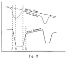
- a wheel When a wheel begins to skid, it will normally decelerate at a rate which is greater than the maximum rate at which the vehicle can decelerate. This deceleration can be detected and taken as an early indication that a skid is imminent. As the skid develops, the speed of the wheel will fall substantially below the speed of the vehicle on the road. If the vehicle speed is known, the difference between vehicle speed and wheel speed (wheel slip) can be used as another indication that a skid is developing. When some predetermined combination of wheel slip and deceleration have been seen, the wheel will move into state 1 (box 62). This transition occurs at point A on Fig. 2.
- State 1 is the pressure dump state.
- the pressure in the brake associated with that wheel will be reduced at a rapid rate.
- the braking medium hydroaulic fluid or air
- the rate at which the pressure drops will depend on the pressure in the brake.
- the appropriate duration for the pressure dump will depend on the road surface over which the wheel is running. On a high friction surface, the brake pressure will be high and so the pressure dump rate will be high. Also the wheel will recover from a skid while there is still a substantial pressure in the brake. In this case a very short dump will be appropriate. On low friction surfaces, the dump rate is much slower, and the pressure must be dropped to a very low value before the wheel will recover from the skid.
- the pressure dump must be much longer.
- the decision to terminate the pressure dump will therefore depend on a judgement of surface friction. On high friction surfaces, the pressure dump might be terminated while the wheel is still decelerating, but the rate at which it is decelerating is reducing. On lower friction surfaces, the pressure dump might continue until the wheel starts to re-accelerate, or even until the wheel is running once again at vehicle speed. When the conditions for termination of the pressure dump have been met, the wheel will move into a state 2 (box 64). This transition occurs at point B on Fig. 2.
- State 2 is the wheel recovery monitoring state. When signs of wheel recovery appropriate to the surface have been seen and the pressure dump has been terminated, the brake pressure will be held at a constant level while the wheel recovery is monitored. On low friction surfaces, the wheel skid will be almost over before the wheel moves into state 2, but on high friction surfaces, the wheel speed might still be reducing. In either case, the brake pressure should have been reduced enough to allow the wheel to recover from the skid and return to running at vehicle speed.
- the logic associated with state 2 generates expected values for wheel speed and acceleration which will, if followed, bring the wheel back up to vehicle speed in an acceptable time. If the wheel speed and acceleration do not meet these expected values, then the wheel will move back into state 1 and further pressure will be dumped.
- the state O logic controls the way in which brake pressure is re-applied. Minimum stopping distances are achieved by controlling the pressure in the brake at a high level on average. The brake pressure should therefore be maintained just below the level which will cause the wheel to skid (skid-pressure). Since this pressure can, in practice, change during a stop, the appropriate level of braking cannot be known, and so brake pressure must be re-applied until the wheel is made to skid again. On high friction surfaces, the brake pressure is often dumped to a level far below skid pressure, and so re-apply must be rapid in order to restore a high level of braking.
- the re-apply rate should be reduced to delay the next skid, and so maximise the time spent with the brake pressure at a high level.
- the wheels will skid at very low brake pressures, and so a very slow brake apply should be used from the start.
- Many electronic braking systems do not have any means of measuring brake pressures, so the decisions about pressure re-apply must be taken on the basis of a judgement of surface friction and a record of past ABS control activity. In systems which do have direct measurement of brake pressures, both the skid-pressure and the brake pressure during re-apply can be measured, and so decisions about pressure re-apply can be simplified.
- Vehicle speed is estimated by monitoring and filtering the speed signals from all of the road wheels. When wheels are skidding, this estimate can be improved by using a measurement of vehicle acceleration from a chassis mounted accelerometer if this is fitted as part of the system.
- Surface friction can be judged from vehicle-wide behaviour, such as vehicle deceleration, or from the behaviour of an individual wheel, such as re-acceleration rate after a wheel skid or skid-pressure if this can be measured. The information used to judge surface friction may be different for different decisions within the ABS logic.
- the control of brake pressure in response to wheel skidding is performed entirely by the master controller.
- a disadvantage with this system is that there is a delay imposed by the need to communicate wheel speed information to the master controller, and later communicate brake pressure demands back to the local valves. This slows the response of the system to sudden skids, which can reduce the level of performance, particularly on low friction surfaces.
- the arrangement is such that, if the local controller for either brake associated with the rear axle, detects a pressure level which is too high for the prevailing road conditions ie. wheel slip, then it signals the master controller accordingly so that the master controller can calculate the appropriate pressure level on the front brakes at which the front wheels will skid, given a knowledge of the braking ratio for the vehicle. The master controller then passes this information on to the front controllers as an expected front skid pressure. Thereafter, the local controllers take all ABS decisions independently of each other and the master controller.
- this is an example of a system in which a part of the anti-lock brake control logic for a wheel is performed by the electronic controller associated with the pressure control valve for that wheel, while another part of the anti-lock brake control logic effective for that wheel is performed by the master electronic controller.
- an electronically controlled braking system incorporating anti-lock brake control and comprising a plurality of brake pressure control valves with associated electronic control units which communicate with one or more master electronic control units, wherein part of the anti-lock brake control logic for a wheel is performed by the electronic control unit associated with the pressure control valve for that wheel, with the remainder of the anti-lock brake control logic for that wheel being performed by said one or more master electronic control units which are in communication with the valve-associated electronic control units, and wherein the valve-associated electronic unit includes skid detection logic which causes brake pressure at the associated wheel to be reduced temporarily in response to a wheel skid condition detected thereby, brake pressure at that wheel being controlled thereafter according to demands communicated to the control unit from the master control unit.
- signals from a wheel speed transducer are provided to the electronic control unit associated with the brake pressure control valve which controls the brake pressure at the wheel fitted with the wheel speed transducer.
- the valve-associated electronic control unit can be arranged to halt the reduction in brake pressure in response to a change in wheel behaviour which may indicate that the reduction in brake pressure has been effective in controlling the wheel skid.
- the one or more master electronic control units are associated with and directly control one or more brake pressure control valves as well as communicating with other valve-associated electronic control units on the vehicle.
- the ABS control logic is shared between the local controller and the master controller, with most of the complex logic performed by the master controller, but the response-time critical logic performed locally.
- the local controller within the valve monitors the wheel speed with a relatively simple skid detection algorithm. If a local controller detects a skid as its own wheel, it overrides the brake pressure demand from the master controller, and immediately reduces pressure at the wheel at the fastest rate possible. Communication with the master controller continues unaffected by the pressure dump.
- the master controller which contains more sophisticated skid detection logic together with the pressure re-apply control logic, recognises that the local controller has taken action to control a skid, and uses the vehicle-wide information that is available to it to calculate the appropriate pressure response to follow the initial dump. When this new brake demand is received by the valve controller, it returns to its normal mode of operation, matching the brake pressure to the demand from the master, and pays no further attention to the behaviour of the wheels until instructed by the master controller.
- a system in accordance with this invention has the advantages of both of the known systems described initially. Only the master controller performs full ABS control, and so only the master controller needs the processing power to do this, and only the master controller needs to be able to observe the behaviour of all of the wheels.
- the simple skid detection logic in the valve controller which is responsible for the rapid reduction in brake pressure in the event of impending wheel lock does not require the computing power of the master controller and yet is able to provide the speed of response of a fully distributed system.
- the illustrated braking control system comprises a master controller/computer 10 which receives driver braking demand signals D from a pedal operated transducer 12 via a line 14 and communicates with respective local controllers/computers 16a, 16b, 16c, 16d via a common communications bus 18.
- Each of the local controllers 16 is disposed adjacent to and is associated with,a respective pressure control valve 20a, 20b, 20c, 20d for each of the vehicle wheels (four in this example).
- the pressure control valves 20a, 20b control air pressure supplied to brake actuators 22a, 22b associated with the two front wheels 24c, 24b and the pressure control valves 20c, 20d control air pressures supplied to brake actuators 22c, 22d associated with the two rear wheels 24c, 24d.
- each of the wheels 24 is monitored by respective wheel speed sensors 26a, 26b, 26c, 26d coupled to the associated local controllers 16a, 16b, 16c, 16d.
- First and second air reservoirs 28a, 28b supply pressured air to the front and rear valves respectively.
- the pressure trace shows the two rate re-apply described hereinabove.
- Trace 1 in Fig. 2 identifies the vehicle speed;
- trace 2 identifies the wheel speed; and
- trace 3 identifies the brake pressure.
- Fig. 3 shows a simplified signal flow through one local valve controller 16 and its master controller 10. In the case of a four-wheeled vehicle, there would be, in one possible embodiment, three other local valve controllers 16 with the same connections to the single master controller 10.
- the local valve controller 16 monitors the signals S from an associated wheel speed sensor 26 (not shown in Fig. 3) and converts these in a measuring element 34 into a digital wheel speed value S' which is passed to the master controller 10 via a line 32 of the control bus 18 of Fig. 1.
- the local valve controller 16 also monitors the signals from a pressure sensor at the local brake actuator and converts these in a measuring element 36 into a digital brake pressure value Ps'.
- the master controller 10 uses the driver's brake demand input D to calculate (in box 38) an appropriate brake pressure P for the wheel, without regard to wheel behaviour.
- the calculated brake pressure demand P is then adjusted by the ABS logic 40 in response to the wheel speed information S' which is communicated from the local valve controller 16 on line 32.
- This adjusted demand Pa is communicated via a line 42 of the bus 18 to the local valve controller 16 which will normally generate pressure control signals to match the brake pressure to the demand from the master controller 10.
- the ABS logic 40 in the master will detect this and will respond by reducing the demanded pressure Pa transmitted to the local valve controller 16.
- delays in the communication of wheel speed signal S' from the valve, and brake demand Pa from the master controller 10 indicated diagrammatically in Fig.
- Simple skid detection logic 46 within the valve controller 16 monitors the wheel speed S' and can generate a pressure dump signal Pd which will override for a limited period the brake pressure demand Pa communicated from the master controller 10 to a brake pressure control element 48 which supplies the pressure control signals Pc for the brake actuator 22 (not shown in Fig. 3).
- the master controller 10 also measures vehicle acceleration in block 50 to provide a digital acceleration signal F' based on a signal F from a vehicle-mounted accelerometer (not shown).
- the master controller 10 uses this signal F' together with the wheel speed signals S' received from the several local valve controllers 16 to calculate in box 52 an estimated vehicle speed Vs. It also uses both the estimated vehicle speed Vs and the calculated vehicle acceleration F' in the ABS logic 40 as indicators of overall vehicle performance.
- Three signals are shown in Fig. 3 to go from the valve controller 16 to the master controller 10. These are the wheel speed signals S' as described above which is used in the ABS logic 40 and to estimate vehicle speed, the brake pressure signals Ps' used in the ABS logic 40, and the pressure dump signal PD from the local skid detection logic 46 in the valve controller. The transference of the latter signal to the master controller is optional.
- the master controller 10 can use this signal, if provided, to determine that the valve controller 16 has dumped brake pressure is response to a wheel skid. If this signal PD is not present then the master controller can make the same determination by having, within its own ABS logic 40, a copy of the skid detection logic (46) of the valve controller 16.
- the master controller 10 receives wheel speed information S' from the valve controller 16, and so can use the same logic as the valve controller to determine what action the valve controller will have taken.
- the master controller 10 calculates vehicle-wide data, for example vehicle speed, and communicates this to the local valve controllers for use by the local controllers in taking ABS decisions.
- Two signals are shown in Fig. 3 to go from the master controller 10 to the valve controller 16.
- One of these is the brake pressure demand signal Pa from the ABS logic 40.
- the other is a signal I which can inhibit local skid detection within the valve controller 16 and force the valve to match brake pressure to the demanded pressure Pa.
- the second signal is again optional. On a system where the signal I is present, it can be used to inhibit local ABS activity in the event that a wheel speed sensor becomes faulty and gives a false indication of wheel skidding. In addition, it can be used to fix the change from local ABS control to central ABS control after the pressure dump part of the ABS cycle has been completed. If this signal I is not present, then these decisions would be taken locally within the valve controller 16.
- Fig. 4 shows a simplified diagram of an air braked vehicle in which the master controller 10' also serves as a local pressure controller for the two rear wheels 24c, 24d while the front wheels 24a, 24b are controlled by separate local pressure controllers 16a, 16b as in the case of Fig. 1. Apart from the latter variation, the system of Fig. 4 is identical to that of Fig. 1.
- Fig. 6 is a simplified diagram of a still further version of a system architecture incorporating the present invention in which there is a single central master controller 10'', one module 70 incorporating one pressure control valve 20e and one local valve controller 16 which is disposed at the front of the vehicle and controls both front brakes to the same pressure, and one module 72 incorporating two pressure control valves 20f, 20g and one local valve controller 16f which controls the pressure in the two rear brakes independently.
- a further variation of this architecture could include a third axle which is controlled either by an additional single channel module of the type that controls the front brakes, or by an additional two channel module of the type which controls the rear brakes.
- a fourth axle in this architecture could be controlled by linking the additional brakes on the same side of the vehicle on an adjacent axle, without additional control modules.
- a "master electronic control unit (ECU)" is one which contains part of the ABS algorithm which is concerned with system-wide data, and supplies brake pressure demands to a valve-associated ECU; and a “valve-associated ECU/local electronic control unit” is one which contains another part of the ABS algorithm which is concerned only with local data, and which can override pressure commands from the master ECU.
- the partially distributed ABS control can be applied to some and not all of the brakes of the system.
- the ABS can be shared between the master ECU and some, but not all, of the valve-associated electronic control units. Those wheels which are controlled by valve-associated electronic unit containing no ABS logic, have ABS control performed entirely by the master controller.
- a particular application of the latter system has ABS control logic for the front axle shared between the master controller and the valve controller which controls the front axle. ABS control logic for other axles on the vehicle is contained entirely within the master electronic control unit/or units.
Description
Claims (14)
- An electronically controlled braking system incorporating anti-lock brake control and comprising a plurality of brake pressure control valves (20a; 20b; 20c; 20d) with associated electronic control units (16a; 16b; 16c; 16d) which communicate with one or more master electronic control units (10), and wherein part of the anti-lock brake control logic for a wheel is performed by the electronic control unit (16a; 16b; 16c; 16d) associated with the pressure control valve for that wheel, with the remainder of the anti-lock brake control logic for that wheel being performed by said one or more master electronic control units (10) which are in communication with the valve-associated electronic control units (16a; 16b; 16c; 16d), characterised in that the valve-associated electronic unit (16) includes skid detection logic (46) which causes brake pressure at the associated wheel to be reduced temporarily in response to a wheel skid condition detected thereby, brake pressure at that wheel being controlled thereafter according to demands (Pa) communicated to the control unit (16) from the master control unit (10).
- An electronically controlled braking system as claimed in claim 1, in which signals from a respective wheel speed transducer (26a;26b;26c;26d) are provided to the electronic control unit (16a;16b;16c;16d) associated with the brake pressure control valve (20a;20b;20c;20d) which controls the brake pressure at the wheel fitted with the wheel speed transducer (26a;26b;26c;26d).
- An electronically controlled braking system as claimed in claim 1 or 2, wherein the valve-associated electronic control unit (16) is arranged to override the pressure demand signals from the master controller for a time period which is related to the delays inherent in the system architecture such that the valve (20) will return to controlling brake pressure in response to demands from the master control unit (10) when the pressure demand (Pa) received from the master controller (10) has been modified by the ABS logic (40) in the master controller (10) in response to said wheel skid.
- An electronically controlled braking system as claimed in claim 1 or 2, wherein the skid detection logic (46) in the valve-associated electronic control unit (16) is responsive to a detected change in wheel behaviour which indicates that the reduction in brake pressure may have been effective in controlling the wheel skid, to halt the reduction in brake pressure.
- A system as claimed in claim 2, in which the master electronic control unit (10) receives wheel speed measurements made by the valve-associated electronic control units (16a; 16b; 16c; 16d) and combines these to establish an estimate of vehicle speed.
- A system as claimed in claim 5, in which the master electronic control unit (10) uses a measurement of vehicle acceleration, derived from an accelerometer mounted on the vehicle, in its estimation of vehicle speed.
- A system as claimed in claim 5 or 6, in which said estimate of vehicle speed is transmitted to a valve-associated electronic control unit (16a; 16b; 16c; 16d) for use in taking local control decisions at the latter unit.
- A system as claimed in any of claims 1 to 7, in which a valve-associated electronic control unit (16a; 16b; 16c; 16d) sends a specific signal (Pd) to the master electronic control unit (10) when the latter valve-associated electronic unit (16a; 16b; 16c; 16d) takes a decision to set a brake pressure to a level determined by anti-lock brake control logic in that unit (16) rather than to a level demanded by said master electronic control unit (10).
- A system as claimed in any of claims 1 to 7, in which the master electronic control unit (10) sends a specific signal (I) to a valve-associated electronic control unit (16) which forces said valve-associated electronic control unit (16) to set the brake pressure in response to the brake pressure demand (Pa) sent from said master electronic control unit (10), irrespective of any wheel behaviour.
- An electronically controlled braking system as claimed in any of claims 1 to 9, in which there is one master electronic control unit (10) for the whole vehicle, and one brake pressure control valve (20) for each wheel on the vehicle.
- An electronically controlled braking system as claimed in any of claims 1 to 9, in which said one or more master electronic control units (10) are associated with and directly control one or more brake pressure control valves (20) as well as communicating with other valve-associated electronic control units (16) on the vehicle.
- A system as claimed in any of claims 1 to 9, in which a brake pressure control valve (20) controls the brake pressure at two or more wheels.
- A system as claimed in any of claims 1 to 9, in which two or more brake pressure control valves (20) share a common valve-associated electronic unit (16).
- A system as claimed in claim 1, in which the anti-lock brake logic is divided between said one or more master electronic control units (10) and the valve-associated control units (16) such that all of the valve-associated control units (16) contain part of the ABS control logic for every wheel that they control.
Applications Claiming Priority (2)
| Application Number | Priority Date | Filing Date | Title |
|---|---|---|---|
| GB9322956 | 1993-11-08 | ||
| GB939322956A GB9322956D0 (en) | 1993-11-08 | 1993-11-08 | Electronic braking control system |
Publications (2)
| Publication Number | Publication Date |
|---|---|
| EP0652145A1 EP0652145A1 (en) | 1995-05-10 |
| EP0652145B1 true EP0652145B1 (en) | 1998-06-10 |
Family
ID=10744796
Family Applications (1)
| Application Number | Title | Priority Date | Filing Date |
|---|---|---|---|
| EP94308104A Expired - Lifetime EP0652145B1 (en) | 1993-11-08 | 1994-11-03 | Electronic braking control system |
Country Status (5)
| Country | Link |
|---|---|
| US (1) | US5575543A (en) |
| EP (1) | EP0652145B1 (en) |
| JP (1) | JPH07205782A (en) |
| DE (1) | DE69410931T2 (en) |
| GB (1) | GB9322956D0 (en) |
Families Citing this family (22)
| Publication number | Priority date | Publication date | Assignee | Title |
|---|---|---|---|---|
| DE19503076A1 (en) * | 1995-02-01 | 1996-08-08 | Teves Gmbh Alfred | Method for operating an anti-lock motor vehicle brake system |
| DE19508559C2 (en) * | 1995-03-10 | 2003-07-17 | Bosch Gmbh Robert | Slip-controlled brake system for commercial vehicles |
| GB9507368D0 (en) * | 1995-04-08 | 1995-05-31 | Lucas Ind Plc | Differential braking control in road vehicles |
| JP3709087B2 (en) * | 1998-12-16 | 2005-10-19 | 株式会社日立製作所 | Brake control device |
| DE19923458A1 (en) | 1999-05-21 | 2000-11-30 | Knorr Bremse Systeme | Electronically controlled braking system |
| DE19957632B4 (en) * | 1999-11-30 | 2010-12-30 | Volkswagen Ag | Wheel brake assembly and method for controlling the wheel braking torque |
| DE10033347B4 (en) * | 2000-07-08 | 2010-09-16 | Robert Bosch Gmbh | Method and device for controlling a decentralized braking system of a vehicle |
| US6668225B2 (en) * | 2000-11-29 | 2003-12-23 | Visteon Global Technologies, Inc. | Trailer control system |
| US7293842B2 (en) * | 2003-07-02 | 2007-11-13 | Haldex Brake Products Ltd. | Control network for vehicle dynamics and ride control systems having distributed electronic control units |
| DE10359040B4 (en) * | 2003-12-17 | 2006-03-23 | Knorr-Bremse Systeme für Nutzfahrzeuge GmbH | Electronically controlled braking system |
| US7020551B2 (en) * | 2003-12-23 | 2006-03-28 | Bendix Commercial Vehicle Systems Llc | Roll stability control system |
| US8746812B2 (en) | 2004-10-08 | 2014-06-10 | Marcia Albright | Brake control unit |
| US8789896B2 (en) | 2004-10-08 | 2014-07-29 | Cequent Electrical Products | Brake control unit |
| US7258404B2 (en) * | 2004-11-11 | 2007-08-21 | Hydro-Aire, Inc. | Antiskid control-combined paired/individual wheel control logic |
| US20090276133A1 (en) * | 2008-05-05 | 2009-11-05 | Goodrich Corporation | Aircraft brake control system and method |
| DE102012003106C5 (en) * | 2012-02-16 | 2022-01-27 | Knorr-Bremse Systeme für Nutzfahrzeuge GmbH | Method for determining a brake pressure value using characteristic curves |
| JP5884244B2 (en) * | 2013-06-19 | 2016-03-15 | オートリブ日信ブレーキシステムジャパン株式会社 | Brake hydraulic pressure control device for vehicles |
| AU2017326530A1 (en) | 2016-09-16 | 2019-05-02 | Horizon Global Americas Inc. | Driver and diagnostic system for a brake controller |
| US10363910B2 (en) | 2016-12-07 | 2019-07-30 | Horizon Global Americas Inc. | Automated gain and boost for a brake controller |
| DE102018123997A1 (en) * | 2018-09-28 | 2020-04-02 | Knorr-Bremse Systeme für Nutzfahrzeuge GmbH | Electro-pneumatic pressure control module with integrated inertial sensor |
| DE102018123996A1 (en) * | 2018-09-28 | 2020-04-02 | Knorr-Bremse Systeme für Nutzfahrzeuge GmbH | Central electro-pneumatic pressure control module with integrated central brake control unit |
| DE102019210271A1 (en) * | 2019-07-11 | 2021-01-14 | Robert Bosch Gmbh | Brake system and method for braking a motor vehicle |
Citations (1)
| Publication number | Priority date | Publication date | Assignee | Title |
|---|---|---|---|---|
| US4850650A (en) * | 1988-09-02 | 1989-07-25 | General Motors Corporation | Hierarchical brake controller |
Family Cites Families (7)
| Publication number | Priority date | Publication date | Assignee | Title |
|---|---|---|---|---|
| JPS5918683B2 (en) * | 1974-04-25 | 1984-04-28 | 旭光学工業 (株) | wide angle photo lens |
| DE3413735A1 (en) * | 1984-04-12 | 1985-10-17 | Robert Bosch Gmbh, 7000 Stuttgart | PRESSURE CONTROL VALVE FOR PRESSURE-OPERATED BRAKING SYSTEMS |
| US4749238A (en) * | 1987-04-13 | 1988-06-07 | Allied Corporation | Electronically controlled fluid pressure braking system |
| US4787683A (en) * | 1987-09-11 | 1988-11-29 | Allied-Signal Inc. | Electro-pneumatic braking system with deceleration control |
| DE4006096C2 (en) * | 1990-02-27 | 1999-08-05 | Teves Gmbh Alfred | Hydraulic braking device for motor vehicles |
| JPH04114203A (en) * | 1990-09-04 | 1992-04-15 | Fuji Heavy Ind Ltd | On-vehicle electronic control system |
| US5288139A (en) * | 1992-06-05 | 1994-02-22 | Allied-Signal Inc. | Electropneumatic braking system |
-
1993
- 1993-11-08 GB GB939322956A patent/GB9322956D0/en active Pending
-
1994
- 1994-11-03 DE DE69410931T patent/DE69410931T2/en not_active Expired - Lifetime
- 1994-11-03 EP EP94308104A patent/EP0652145B1/en not_active Expired - Lifetime
- 1994-11-08 US US08/337,407 patent/US5575543A/en not_active Expired - Lifetime
- 1994-11-08 JP JP6274015A patent/JPH07205782A/en active Pending
Patent Citations (1)
| Publication number | Priority date | Publication date | Assignee | Title |
|---|---|---|---|---|
| US4850650A (en) * | 1988-09-02 | 1989-07-25 | General Motors Corporation | Hierarchical brake controller |
Also Published As
| Publication number | Publication date |
|---|---|
| DE69410931T2 (en) | 1998-10-08 |
| JPH07205782A (en) | 1995-08-08 |
| DE69410931D1 (en) | 1998-07-16 |
| US5575543A (en) | 1996-11-19 |
| GB9322956D0 (en) | 1994-01-05 |
| EP0652145A1 (en) | 1995-05-10 |
Similar Documents
| Publication | Publication Date | Title |
|---|---|---|
| EP0652145B1 (en) | Electronic braking control system | |
| US5669678A (en) | Process and apparatus for determining the application pressures and characteristic brake values of a vehicle | |
| US5684702A (en) | Control system having data correlation for controlling a vehicular anti-lock braking system | |
| US4902076A (en) | Antilock brake control method for motor vehicle | |
| US6144928A (en) | Method and device for determining vehicular mass | |
| CA1313903C (en) | Anti-lock control method for vehicle | |
| US4917444A (en) | Antilock brake control method and system for motor vehicles | |
| EP1603781B1 (en) | An anti-lock brake system with continuous wheel slip control | |
| GB2206387A (en) | Vehicle skid control system | |
| US5119303A (en) | Brake-force control system for vehicles | |
| US6206488B1 (en) | Method and apparatus for controlling a braking system | |
| US4881785A (en) | Anti-lock brake control method and system for motor vehicles | |
| JP2592085B2 (en) | Anti-lock device | |
| US4984164A (en) | Anti-lock control method and apparatus for vehicles | |
| US6312066B1 (en) | Method for improving the regulation behavior of an ABS system in off-the-road driving | |
| US9175701B2 (en) | Speed control strategy | |
| US4769758A (en) | Antiskid control system responsive to road surface reaction | |
| US6789858B2 (en) | Braking force control system for vehicle | |
| US5588719A (en) | Anti-wheel-lock braking system for a motor vehicle | |
| US20010013723A1 (en) | Anti-lock brake control device and method | |
| JP3545060B2 (en) | Anti-skid control method and anti-skid control device | |
| US5542756A (en) | Reduced brake switch dependence control method and system for vehicle anti-lock brake system | |
| US5971502A (en) | Secondary braking control | |
| US6041277A (en) | Method of improving the control characteristics of an antilocking system (ABS) | |
| JP3449336B2 (en) | Vehicle brake control device |
Legal Events
| Date | Code | Title | Description |
|---|---|---|---|
| PUAI | Public reference made under article 153(3) epc to a published international application that has entered the european phase |
Free format text: ORIGINAL CODE: 0009012 |
|
| AK | Designated contracting states |
Kind code of ref document: A1 Designated state(s): DE FR GB IT SE |
|
| 17P | Request for examination filed |
Effective date: 19951005 |
|
| 17Q | First examination report despatched |
Effective date: 19961105 |
|
| GRAG | Despatch of communication of intention to grant |
Free format text: ORIGINAL CODE: EPIDOS AGRA |
|
| GRAG | Despatch of communication of intention to grant |
Free format text: ORIGINAL CODE: EPIDOS AGRA |
|
| GRAH | Despatch of communication of intention to grant a patent |
Free format text: ORIGINAL CODE: EPIDOS IGRA |
|
| GRAH | Despatch of communication of intention to grant a patent |
Free format text: ORIGINAL CODE: EPIDOS IGRA |
|
| GRAA | (expected) grant |
Free format text: ORIGINAL CODE: 0009210 |
|
| AK | Designated contracting states |
Kind code of ref document: B1 Designated state(s): DE FR GB IT SE |
|
| ITF | It: translation for a ep patent filed |
Owner name: ING. A. GIAMBROCONO & C. S.R.L. |
|
| REF | Corresponds to: |
Ref document number: 69410931 Country of ref document: DE Date of ref document: 19980716 |
|
| ET | Fr: translation filed | ||
| PG25 | Lapsed in a contracting state [announced via postgrant information from national office to epo] |
Ref country code: SE Free format text: LAPSE BECAUSE OF FAILURE TO SUBMIT A TRANSLATION OF THE DESCRIPTION OR TO PAY THE FEE WITHIN THE PRESCRIBED TIME-LIMIT Effective date: 19980910 |
|
| PLBE | No opposition filed within time limit |
Free format text: ORIGINAL CODE: 0009261 |
|
| STAA | Information on the status of an ep patent application or granted ep patent |
Free format text: STATUS: NO OPPOSITION FILED WITHIN TIME LIMIT |
|
| 26N | No opposition filed | ||
| REG | Reference to a national code |
Ref country code: FR Ref legal event code: TP |
|
| REG | Reference to a national code |
Ref country code: GB Ref legal event code: IF02 |
|
| REG | Reference to a national code |
Ref country code: GB Ref legal event code: 732E |
|
| REG | Reference to a national code |
Ref country code: GB Ref legal event code: 732E |
|
| PGFP | Annual fee paid to national office [announced via postgrant information from national office to epo] |
Ref country code: IT Payment date: 20081127 Year of fee payment: 15 |
|
| PGFP | Annual fee paid to national office [announced via postgrant information from national office to epo] |
Ref country code: FR Payment date: 20081112 Year of fee payment: 15 |
|
| REG | Reference to a national code |
Ref country code: FR Ref legal event code: ST Effective date: 20100730 |
|
| PG25 | Lapsed in a contracting state [announced via postgrant information from national office to epo] |
Ref country code: FR Free format text: LAPSE BECAUSE OF NON-PAYMENT OF DUE FEES Effective date: 20091130 |
|
| PGFP | Annual fee paid to national office [announced via postgrant information from national office to epo] |
Ref country code: DE Payment date: 20101027 Year of fee payment: 17 |
|
| PG25 | Lapsed in a contracting state [announced via postgrant information from national office to epo] |
Ref country code: IT Free format text: LAPSE BECAUSE OF NON-PAYMENT OF DUE FEES Effective date: 20091103 |
|
| PGFP | Annual fee paid to national office [announced via postgrant information from national office to epo] |
Ref country code: GB Payment date: 20101103 Year of fee payment: 17 |
|
| GBPC | Gb: european patent ceased through non-payment of renewal fee |
Effective date: 20121103 |
|
| REG | Reference to a national code |
Ref country code: DE Ref legal event code: R119 Ref document number: 69410931 Country of ref document: DE Effective date: 20130601 |
|
| PG25 | Lapsed in a contracting state [announced via postgrant information from national office to epo] |
Ref country code: DE Free format text: LAPSE BECAUSE OF NON-PAYMENT OF DUE FEES Effective date: 20130601 |
|
| PG25 | Lapsed in a contracting state [announced via postgrant information from national office to epo] |
Ref country code: GB Free format text: LAPSE BECAUSE OF NON-PAYMENT OF DUE FEES Effective date: 20121103 |